
 Submit a Paper
 Propose a Special lssue
 Open Access
ARTICLE

Influence of High-Density Bedding Plane Characteristics on Hydraulic Fracture Propagation in Shale Oil Reservoir
1 State Key Laboratory of Shale Oil and Gas Enrichment Mechanisms and Effective, Beijing, 102206, China
2 State Energy Center for Shale Oil Research and Development, Beijing, 102206, China
3 Department of Geotechnical Engineering College of Civil Engineering, Tongji University, Shanghai, 200092, China
4 Petroleum Exploration and Production Research Institute, SINOPEC, Beijing, 102206, China
5 Key Laboratory of Deep Earth Science and Engineering (Sichuan University), Ministry of Education, Chengdu, 610065, China
* Corresponding Author: Haitao Yu. Email:
(This article belongs to the Special Issue: Multiscale, Multifield, and Continuum-Discontinuum Analysis in Geomechanics )
Computer Modeling in Engineering & Sciences 2024, 140(3), 3051-3071. https://doi.org/10.32604/cmes.2024.051832
Received 16 March 2024; Accepted 07 May 2024; Issue published 08 July 2024
 View Full Text
 Download PDF
Abstract
The existence of high-density bedding planes is a typical characteristic of shale oil reservoirs. Understanding the behavior of hydraulic fracturing in high-density laminated rocks is significant for promoting shale oil production. In this study, a hydraulic fracturing model considering tensile failure and frictional slip of the bedding planes is established within the framework of the unified pipe-interface element method (UP-IEM). The model developed for simulating the interaction between the hydraulic fracture and the bedding plane is validated by comparison with experimental results. The hydraulic fracturing patterns in sealed and unsealed bedding planes are compared. Additionally, the effects of differential stress, bedding plane permeability, spacing, and the friction coefficient of the bedding plane are investigated. The results showed that a single main fracture crossing the bedding planes is more likely to form in sealed bedding planes under high differential stress. The decrease in bedding plane permeability and the increase in the friction coefficient also promote the fracture propagating perpendicular to the bedding planes. Shale with high-density bedding planes has a poorer fracturing effect than that with low-density bedding planes, as the hydraulic fracture is prone to initiate and propagate along the bedding planes. Moreover, higher injection pressure is needed to maintain fracture propagation along the bedding. An increase in bedding density will lead to a smaller fracturing area. Fracturing fluid seepage into the bedding planes slows shale fracturing. It is recommended that increasing the injection flow rate, selecting alternative fracturing fluids, and employing multi-well/multi-cluster fracturing may be efficient methods to improve energy production in shale oil reservoirs.Keywords
Nomenclature
| Effective stress tensor | |
| Biot coefficient | |
| p | Fluid pressure |
| I | Identity tensor |
| Body force | |
| Medium symbol for rock matrix and fractures/bedding planes | |
| Fluid density | |
| Volumetric strain | |
| q | Flux source term |
| Fluid viscosity | |
| k | Material intrinsic permeability |
| S | Storage coefficient |
| Rock matrix porosity | |
| cw | Fluid compressibility |
| cr | Rock matrix compressibility |
| E | Young’s modulus |
| v | Poisson’s ratio |
| w | Fracture aperture |
| wr, w0 | Residual and initial aperture of bedding planes |
| Dilation induced aperture | |
| uN, uT | Normal displacement and shear displacement |
| ueq | Equivalent opening |
| u | Historically maximum equivalent separation |
| u0 | Fracture threshold opening |
| umax | The maximum aperture |
| td | Cohesive traction |
| Equivalent traction | |
| Normal traction and shear traction | |
| ft | Uniaxial tensile stress |
| Gf | Fracture energy |
| k0 | Penalty parameters |
| Kn, Ks | Normal stiffness and shear stiffness |
| β, κ | Scaling factor for rock strength and fracture energy |
| µ | Coulomb’s friction coefficient |
| ψ | Dilation angle |
The large consumption of petroleum, natural gas and coal resources makes it essential to explore the new energy. According to the statistics, shale oil has the huge development potential in China with its storage capacity approximately 4.48 × 10⁹ t [1–4]. Shale oil production has become an attractive alternative to conventional petroleum industry. The shale oil formation is typically a sedimentary rock with low porosity, low permeability, and high-density bedding planes [5–8]. Hydraulic fracturing is the most effective technology to stimulate the shale oil production by pumping high-pressure fluid into the formation to increase the permeability of the reservoir rock [9,10]. The permeability could be enhanced by generating new fractures or activating the bedding planes/natural fractures. Investigating the formation mechanism of complexed hydraulic fracture network in high-density laminated shale is essential for fracturing design and production estimation.
Understanding the interaction form between hydraulic fracture and bedding plane is a primary task to control the fracturing scheme. Several dominant modes have been observed in laboratory experiments [11–14], such as the bedding plane preventing the hydraulic fracture further propagation, the hydraulic fracture crossing the discontinuities, and the bedding plane is the main path for fracture propagation. The injection volume and confining stress have obvious effects on the pump pressure and hydraulic fracture path. The combined impact of perforation direction and bedding plane angle on fracture morphology were also discussed [15–17]. It is noted that these experiments are generally conducted by creating a pre-existing bedding plane inside the sample or obtaining the outcrop sample directly from the gas and oil reservoir. Although laboratory experiments can provide insights into hydraulic fracture propagation, they are usually limited to small scales, and it is difficult to quantify the effect of bedding plane characteristics.
Numerical simulation serves as an effective tool for studying the evolution of hydraulic fracture propagation and has achieved notable progress. Various continuum-based and discontinuum-based numerical methods were developed to analyze the crack propagation path when the pre-existing fracture exists in the rock. These methods include the extended finite element method [18–21], the phase field method [22,23], the discrete element method [24–27], the 3D lattice method [28–31], peridynamics [32,33] and the hybrid finite-discrete element method [34,35]. Using these methods, researchers have discussed the influence of stress regime, fracturing fluid viscosity, bedding dip, and the approach angle of the hydraulic fracture to the pre-existing discontinuity. Furthermore, criteria for the judgement of fracture propagation path (cross, arrest, open) have been proposed. Wu et al. [36] discovered that the slip properties and the bedding intrinsic permeability can also determine the fracturing characteristics. Zheng et al. [37] discussed the hydraulic fracture crossing ability considering the influence of injection scheme and injection parameters, as well as established the evaluation standard for the hydraulic fracture penetration. Ma et al. [38] coupled the cohesive zone model in the framework of the extended finite element method to consider the elastic-plastic damage of rock and further proposed the major control factors for larger fracturing area in the rocks with different lithological combinations. Xie et al. [39] constructed a 3D hydro-mechanical coupled model in layered rock and found that the shear displacement of the bedding planes affecting the hydraulic fracture width.
Most previous research considered only the existence of a single bedding plane or two parallel bedding planes opposite the wellbore and assumed the bedding planes were sealed under the in-situ stress regime. However, in shale oil reservoirs, bedding planes are generally developed with lamina thicknesses ranging from 0.01 to 1 m [40–42]. Based on the geological survey data in Gulong Shale Oilfield, China, Meng et al. [43] also observed that the density of the horizontal bedding seams may varies from several hundred per meters to several thousands per meter. The fluid flow, rock matrix properties, and continuous-discontinuous mechanical response are significantly affected by the existence of these weak discontinuities. Considering the high-density bedding planes, Yin et al. [44] established a 100 mm × 100 mm layered rock model with a bedding plane spacing of 2.5 mm in 2D Particle Flow Code (PFC2D). They analyzed the distribution of fracturing induced tensile and shear failures of the layered rock and investigated the crack propagation path for a multi-cluster horizontal well. Although these results reflect that the interbedding fracture interaction leads to a complex fracture network, few researchers have discussed the influence of different structural, hydro, and mechanical features of high-density bedding planes on hydraulic fracturing and interaction modes.
In this study, we developed a hydraulic fracturing model in high-density laminated rocks within the framework of the unified pipe-interface element method (UP-IEM). The UP-IEM considers that fluid flow and fractures propagate along 1D pipes. The hydraulic fracture propagation, branching and coalesce are tracked base on the cohesive zone theory, while the tensile and shear failures of the bedding plane are governed by the classical Coulomb’s friction law. This hydro-mechanical model could provide a guidance for hydraulic fracture initiation and propagation in high-density bedding plane. The main structure of this paper is as follows: Section 2 describes the mathematical model and numerical method for hydraulic fracturing in laminated rocks. In Section 3, the numerical results of hydraulic fracture-bedding plane interactions are verified by a laboratory experiment in previous published paper. Section 4 presents a sensitivity analysis to better understand the hydraulic fracturing behavior in high-density bedding planes. Section 5 summarizes the concluding remarks and provides directions for future research.
2 Mathematical Model and Numerical Method
2.1 Hydro-Mechanical Coupled Model
The governing equation for the mechanical equilibrium of the fractured rock is expressed based on the porelastic theory as follows:
where
The fluid flow in rock matrix, hydraulic fractures, and bedding planes is written based on Darcy’s law, and the mass conservation equation is expressed as:
where
in which
2.2 Cohesive Zone Model and Frictional Slip Model
The key to hydraulic fracturing modeling in layered rock lies in capturing the crack initiation, propagation, branch and coalesce, as well as calculating the tensile failure and frictional slip of bedding planes. Zero-thickness cohesive elements proposed by Barenblatt [46] are generated between the matrix triangular elements to represent the hydraulic fractures and bedding planes. The crack path is determined using pre-defined cohesive interface elements. As shown in Fig. 1, the cohesive traction of the hydraulic fracture is determined by the interface separation by following a linear softening law [47]:
with
where
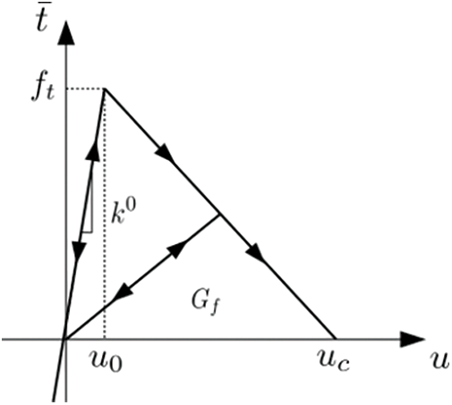
Figure 1: Linear softening law for cohesive zero-thickness interface element
The frictional slip behavior of the bedding planes under normal compressive loading is controlled by classical Coulomb’s friction law as given in [49]:
where
Before the sliding of the interface element, the shear traction is
in which
As indicated in Eq. (2), the permeability of the discontinuous surface (hydraulic fractures and bedding planes) is related to the hydraulic aperture. The generation of hydraulic fractures is considered as tensile failure, thus, the aperture of the hydraulic fracture is equal to the positive normal displacement jump across the damaged interface elements [48]:
For the bedding planes under normal compressive loading, the aperture variation of bedding planes is calculated based on the bedding normal and shear deformation. Fang et al. [50] also proposed that the natural fracture permeability depends on the slip rate and surface asperities. Therefore, the total aperture for bedding planes is expressed as [51,52]:
where
2.4 The Basic Theory of UP-IEM
UP-IEM simplifies the hydraulic fracturing in inherently laminated rocks in a 2D domain into a 1D problem. As shown in Fig. 2, the intrinsic hydraulic properties of the rock matrix are assigned to the 1D pipes based on the discretization the finite volume theory, in which the pipes are the edges the triangular elements. The bedding planes share the same edge with the triangular elements and are established using zero-thickness interface elements. In addition, the interface elements are generated in the whole domain to model the bedding planes and possible hydraulic fractures by assigning different mechanical properties. For fluid flow, the detailed pipe equivalent coefficients were explained by Yan et al. [53]. This conceptualization is based on precise geometry and material information of the fracture network and rock matrix rather than simplified flow channels. The crack initiation and propagation are controlled by cohesive zone model. In UP-IEM, the unified pipe network method (UPM) and the interface element (IE) are coupled to solve the hydro-mechanical coupled fracture propagation problem. UP-IEM solves hydraulic fracturing in a partitioned coupling way by a semi-explicit integration scheme. The fluid is considered an external force on the mechanical elements to calculate the effective stress. The fluid pressure and mechanical displacement are calculated respectively using UPM and FEM.
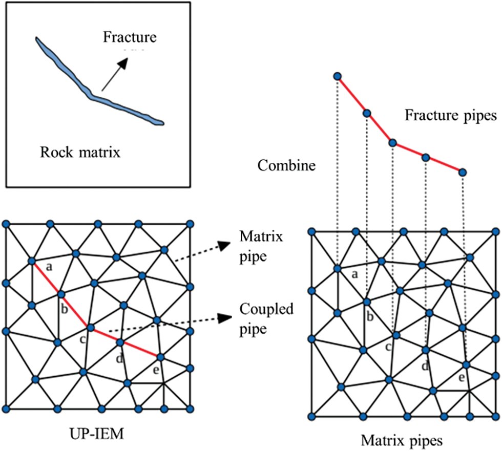
Figure 2: Conception graph of 1D flow pipes in layered rock
UP-IEM has a unique advantage in simulating multi-field coupling and crack propagation in porous fractured medium [53–55]. This section aims to validate the accuracy and reliability of this method in modeling the interaction form of hydraulic fracture and single bedding. The numerical results are compared with experimental results published in [11]. As shown in Fig. 3, the size of the hydro stone sample is 300 mm × 300 mm with a pre-existing bedding plane oriented at 60° (tests named as CT4, CT8, and CT21). The fracturing fluid is injected into the block-shaped specimen along the perforation under a constant flow rate Q = 8.2 × 10⁻⁷ m3/s. The material parameters are the following: Young’s modulus is 10 GPa, Poisson’s ratio is 0.2, initial porosity is 0.22, intrinsic permeability is 1 × 10⁻¹⁷ m2, the tensile strength is 3.1 MPa, the fracture energy is 100 N/m, the fluid viscosity is 0.001 Pa.s. The friction coefficient of the bedding plane is 0.7 and the bedding plane is regarded as non-cohesive. The hydro stone sample is a kind of quasi-brittle materials, thus the scaling parameter
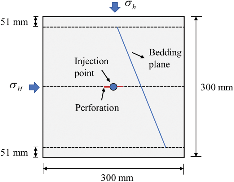
Figure 3: Numerical test schematic model plotted according to experiments of Blanton [11]
Fig. 4 presents the experimental results observed in Blanton’s tests on hydrostone. For experimental tests, CT4, CT8, and CT21 differ in the amount of applied differential stress. They were chosen because they reproduced three types of interactions: crossing, arrest, and opening (see Fig. 4). In the case of CT4, the maximum horizontal stress is 12 MPa and the minimum horizontal stress is 10 MPa, respectively. Fig. 5a shows that the lower part of the bedding plane opens and even propagates because the fluid pressure is greater than the normal compressive (closing) load acting on the bedding plane. However, the upper part of the bedding plane remains partially closed. In the case of CT21, the maximum horizontal stress is 14 MPa and the minimum horizontal stress is 5 MPa, respectively. As observed in Fig. 5b, the fracturing fluid penetrates into the bedding plane due to slippage, and then the hydraulic fracture was arrested. In the case of CT8, the maximum horizontal stress is 20 MPa and the minimum horizontal stress is 5 MPa, respectively. As shown in Fig. 5c, the hydraulic fracture crosses the bedding plane because the bedding plane always keeps a closed situation under the action of high horizontal stress. These observations demonstrate that the numerical results are in good agreement with the laboratory tests. The fluid flow patterns accurately describe the hydraulic fracture propagation path.
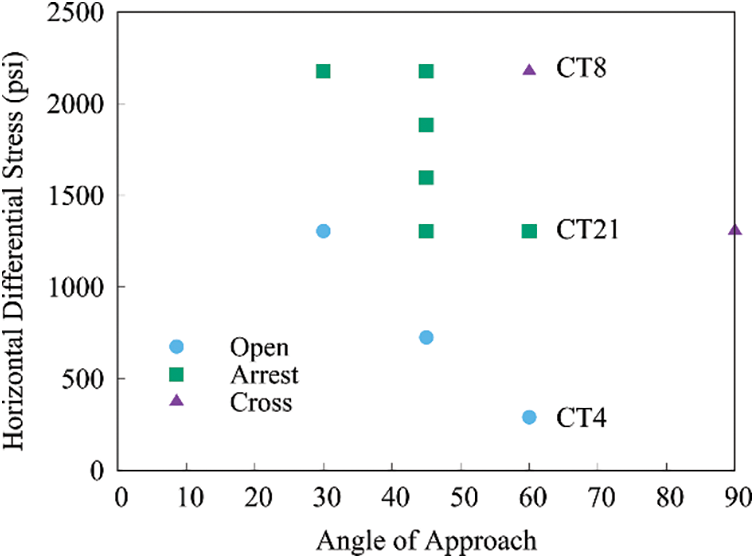
Figure 4: Interaction form of hydraulic fracture and bedding plane observed for different combinations of differential stress and approach angle, plotted according to experimental results of Blanton [11]
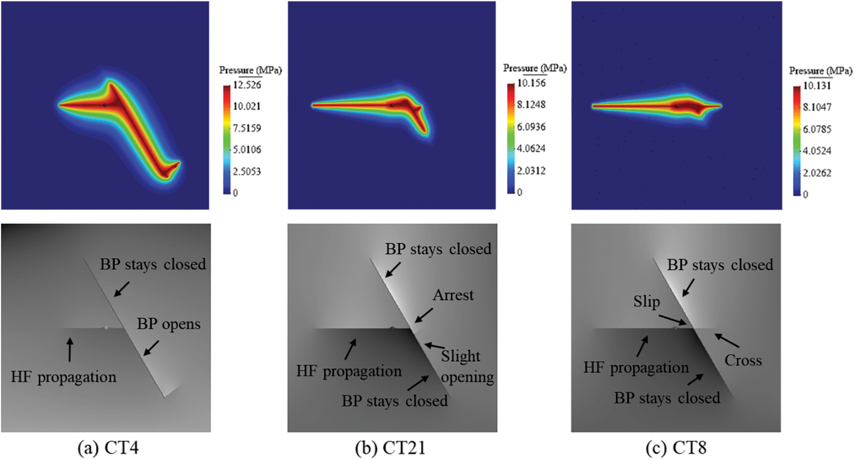
Figure 5: Interaction between hydraulic fracture (HF) and single bedding plane (BP): fluid pressure distribution and fracture propagation path for the case CT4, CT21 and CT8
4 Numerical Results and Analysis
Generally, the bedding planes develop well in shale oil, and the thickness of the lamina ranges from millimeters to meters (see Fig. 6a). In this study, a numerical model with dimensions of 1 m × 1 m considering high-density bedding planes is established, as shown in Fig. 7. The spacing of the bedding planes is 10 mm. The vertical displacements are fixed on the bottom edges. The horizontal stress (
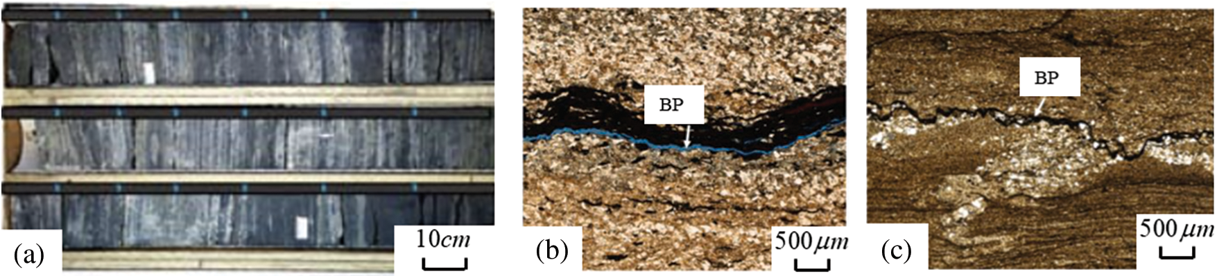
Figure 6: Structural characteristics of shale specimen: (a) thick black shale with beddings replotted according to the sample in [3]; (b) and (c) rough surface of the bedding plane replotted according to the scanning results in [61]
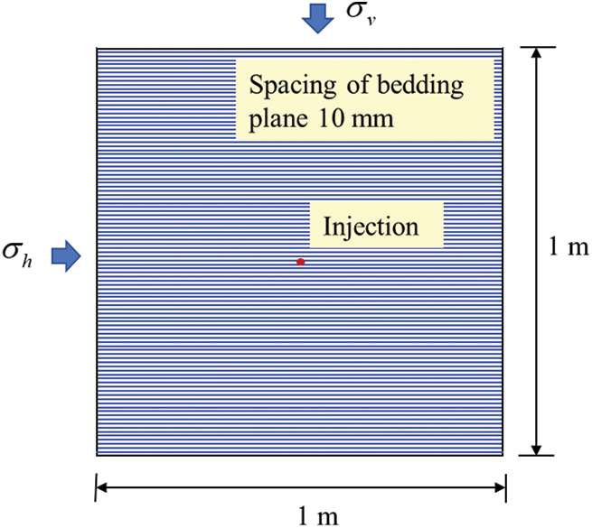
Figure 7: Diagram of a numerical model for hydraulic fracturing in shale with high-density bedding planes

4.2 Effect of Differential Stress
For shale reservoirs with different stress regimes, timing, burial depths, and genetic mechanisms, the bedding planes may present as sealed or unsealed. Previous studies mostly assume the bedding planes are sealed and neglect the initial opening, as shown in Fig. 6. In this section, two sets of cases are conducted to compare hydraulic fracturing behavior in sealed and unsealed bedding planes. The vertical stress is 10 MPa, and the horizontal stresses are 4, 6, 8, and 10 MPa, respectively. Unlike the unsealed bedding planes acting as a fluid flow path, sealed bedding planes no longer provide seepage channel [62]. Nevertheless, the mechanical strength of these two kinds of interface is both weaker than the rock matrix, causing the bedding planes easier to be reactivated and further influencing the formation of hydraulic fracture networks.
Fig. 8 shows the pore pressure distribution for unsealed and sealed bedding planes under different stress regime. It is observed that a single main hydraulic fracture forms more easily under high differential stress. However, influenced by the initial opening of the unsealed bedding planes, the injection fluid tends to penetrate to theses discontinuities, inducing tensile failure or frictional slip and generating a larger fracturing area. A notable difference in the hydraulic fracturing path is observed when the differential stress is 2 MPa. Hydraulic fracture propagates toward the vertical stress direction and crosses the sealed bedding planes. In contrast, three layers of unsealed bedding planes are activated, and their opening increases with continuous fluid injection. When the horizontal stress equals to the vertical stress, the hydraulic fracture initiates and propagates along the bedding planes. Fig. 8 indicates the increased stress difference results in a greater resistance of bedding planes to hydraulic fracturing. Fig. 9 presents the variation in injection pressure. The crack initiation pressure, which is the maximum pressure required to fracture the rock, increases with the increasing horizontal stress. A pressure drop occurs after the rock fractures. It is noted from Figs. 8a and 8b that the injection pressure is almost the same when only one single fracture is formed. However, a larger injection pressure is needed after the crack initiation to keep the bedding planes open under the influence of a larger horizontal stress. For the same horizontal stress and vertical stress, although the hydraulic fracture propagates along the bedding planes in both cases, the existence of the initial opening facilitates the flow and causes a lower injection pressure.
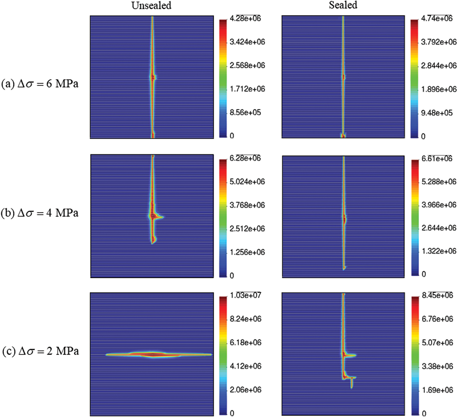
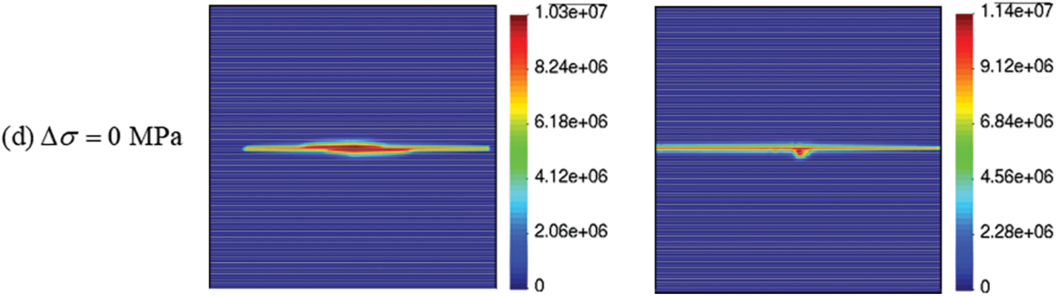
Figure 8: Pore pressure distribution for unsealed and sealed bedding planes under different in-situ stress
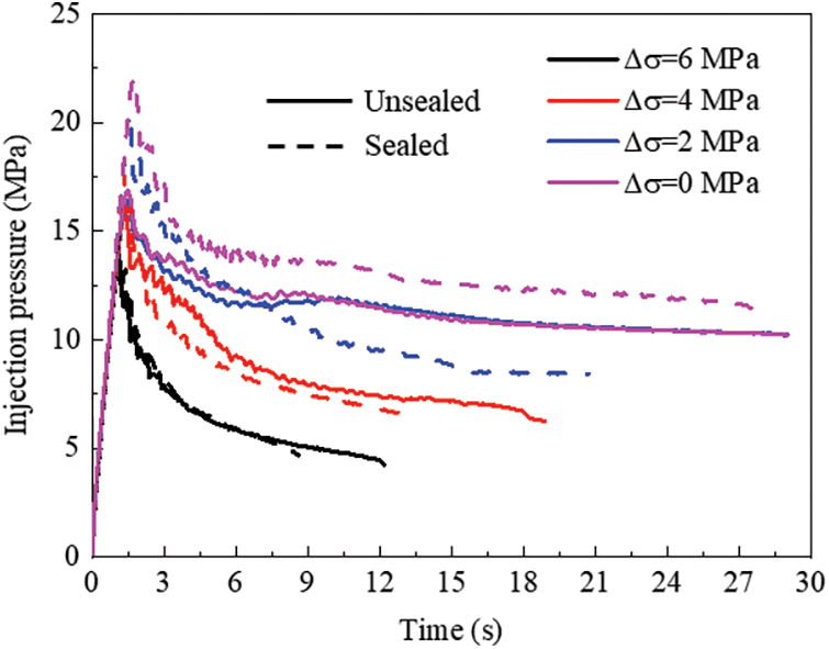
Figure 9: Injection pressure for unsealed and sealed bedding planes under different in-situ stress
4.3 Effect of Bedding Planes Permeability
As described in the previous section, the hydraulic fracture propagation behavior is influenced by the seal characteristics of the bedding planes to a certain extent. Figs. 6b and 6c also show that the geometry of the bedding planes, which affects their permeability, varies significantly. This permeability influences the fluid flow process. Considering the unsealed bedding planes, the aim of this section is to investigate the effect of bedding plane permeability on the hydraulic fracturing pattern, fluid flow pattern, and injection pressure. As stated in Eq. (2), the permeability is directly connected to the aperture of the bedding planes. Therefore, the residual aperture in this study is selected as 170, 400, 600, and 800 μm, respectively. The vertical stress is 10 MPa, and the differential stress is 4 MPa.
Fig. 10 presents the fluid flow patterns and corresponding crack patterns. When the bedding plane aperture is 170 μm, the hydraulic fracture crosses the bedding plane, forming a single main fracture. The hydraulic fracture pattern resembles that of a rock without a bedding plane. Additionally, as seen in Figs. 10c and 10d, an increase in permeability leads to a smaller fracturing area due to fluid penetration into the bedding planes. The compressive load of the pore pressure on the rock mass skeleton makes the hydraulic fracture crossing the bedding planes difficult. A better hydraulic fracturing effect is achieved when the bedding plane permeability is low. Fracturing fluid seepage into the bedding planes slows shale fracturing. As shown in Fig. 11, a lower permeability corresponds to a higher fracture initiation pressure. This is because that the hydraulic fracture tends to cross the low-permeable bedding plane, and a higher injection pressure is necessary to break the host rock than to induce the failure of the bedding planes. However, it is interesting to note that the continuous injection pressure for high-permeable bedding planes is larger than that for low-permeable bedding planes. When the bedding plane aperture is 400, 600, and 800 μm, the injection pressure required to open the bedding planes still exceeds the vertical stress.
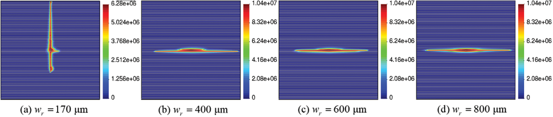
Figure 10: Effect of bedding plane permeability: Pore pressure distribution
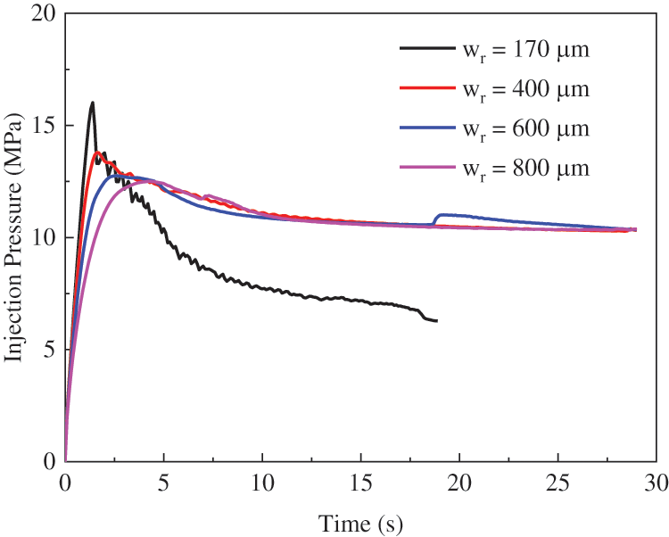
Figure 11: Effect of bedding plane permeability: Injection pressure
4.4 Effect of Bedding Plane Spacing
Previous research has shown that the thickness of bedding planes in typical shale oil reservoirs ranges from 0.01 to 1 m. Although discussions have addressed the interaction modes between hydraulic fractures and bedding planes, the influence of bedding plane spacing has generally been overlooked. Therefore, further investigation of this effect is carried out through hydraulic fracturing simulations with bedding plane spacings of 10, 20, 50, and 100 mm. The vertical stress is set at 10 MPa, and the horizontal stress is set at 8 MPa.
Hydraulic fracturing path corresponding to the fluid pressure distribution for different bedding plane spacings are depicted in Fig. 12. It is observed that hydraulic fractures are easily arrested at spacings of 10 and 20 mm, while a fishbone-like fracture pattern with open bedding planes forms at spacings of 50 and 100 mm. It has been determined that hydraulic fractures are more likely to cross bedding planes as their spacing increases. Additionally, the number of bedding plane layers that the hydraulic fracture crosses also increase. Breaking rock containing high-density bedding planes is challenging. The high compressibility of the bedding planes leads to local stress concentrations, requiring higher pump pressures to assist the hydraulic fracture in crossing the bedding planes. As the bedding plane spacing decreases, the effects of interbedding fracture coalescence become more pronounced. Fig. 13 presents the evolution of injection pressure for different bedding plane spacings, noting that once the single main fracture crosses the bedding planes, the required continuous injection pressure decreases. However, higher injection pressure is needed to counteract the confining stress and keep the bedding planes open.
Figure 12: Effect of bedding plane spacing: Pore pressure distribution
Figure 13: Effect of bedding plane spacing: Injection pressure
A serious of additional fracturing analyses with bedding plane apertures of 400 and 800 μm are conducted as the supplement of the above-mentioned models. The fluid pressure distribution and hydraulic fracture patterns are shown in Fig. 14. When the bedding plane aperture is 800 μm, the hydraulic fractures initiate and propagate parallel to the bedding planes in the three cases (Figs. 14d–14f). Consequently, for high-density and high-permeable bedding planes, the hydraulic fracture is more likely to be arrested and develops along the bedding plane direction.
Figure 14: Pore pressure distribution for different bedding plane spacing and bedding plane permeability
4.5 Effect of Friction Coefficient
Fluid injection-induced bedding plane slipping and opening can significantly affect the permeability of the bedding planes and the redistribution of local stress. Moreover, activation occurrence depends strongly on the frictional characteristics of the bedding planes, as the friction coefficient influences their shear capacity and, thus, the interaction between hydraulic fractures and bedding planes. In this comparative analysis, the vertical stress is 10 MPa, and the horizontal stress is 6 MPa. The friction coefficients are defined as 0.1, 0.3, 0.6, and 0.9, respectively.
Fig. 15 shows that the hydraulically-induced fracture tends to cross the bedding planes for larger friction coefficients, and the bedding planes behave more similarly to cemented bedding planes. A high friction coefficient allows the bedding planes to support substantial shear stresses, transferring loads across the crack faces, enabling the hydraulic fracture to cross the discontinuities and continue to propagate. Conversely, with low friction coefficients, tensile failure and shear slippage of the bedding planes are more likely to occur, and the fluid-induced fracture is then arrested. The fracture-induced stresses are not transmitted to the other side of the bedding plane. The decline in the friction coefficient is not conducive to generating the main penetrating hydraulic fracture. As observed in Fig. 16, the injection pressure before the fracture initiation pressure point remains similar for all cases. After this point, the injection pressure exhibits the analogous trend, dropping noticeably when the friction coefficient is large. However, the injection pressure required to keep the bedding planes open increases as the friction coefficient decreases.
Figure 15: Effect of friction coefficient: Pore pressure distribution
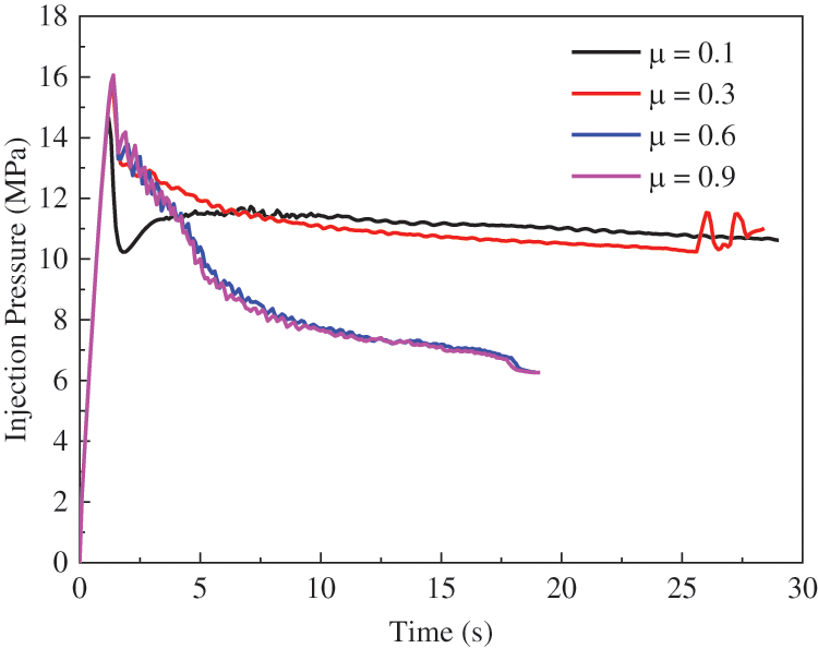
Figure 16: Effect of friction coefficient: Injection pressure
4.6 Effect of Injection Flowrate
According to the above-mentioned results, it has been found that high-density bedding planes negatively affect hydraulic fracturing compared to intact rock and low-density bedding planes under the same material parameters and injection scheme. In order to address whether increasing the injection flow rate can effectively improve hydraulic fracturing, the chosen injection flow rates are 100, 200, 400, and 600 mm3/s. The vertical stress is maintained at 10 MPa, and the horizontal stress is fixed at 6 MPa. Other parameters remain as listed in Table 1.
Fig. 17 provides four representative cases of hydraulic fracturing at different injection flow rates. At a flow rate of 100 mm3/s, the hydraulic fracture will be arrested at the bedding planes. However, increasing the injection flow rate promotes hydraulic fracture propagation perpendicular to the bedding planes toward the vertical stress direction. When the flow rate is sufficient, the main fracture crosses the bedding planes with the bedding planes opened. Consequently, increasing the injection flow rate can be regarded as an efficient method to enhance energy production in shale oil reservoirs with high-density bedding planes.
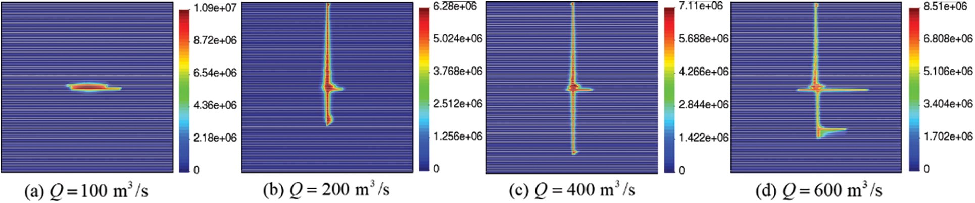
Figure 17: Effect of injection flow rate: Pore pressure distribution
This study develops hydraulic fracturing model in high-density layered shale in the framework of UP-IEM. This model could effectively solve fluid flow in the porous fractured medium and takes into account tensile failure and frictional slip of the bedding planes. The reliability and accuracy of UP-IEM to simulate the interaction mode of hydraulic fracture and bedding plane are validated using experimental results in other published papers. The hydraulic fracturing patterns include three modes in this study: a single main fracture crossing the bedding planes and expanding vertically, crack initiation and development along the surface of the bedding planes, crack expanding vertically and then coalescing with closed or open bedding planes. The hydraulic fracturing behavior in sealed and open bedding planes is investigated. Moreover, the effects of stress regime, bedding plane permeability, spacing, and friction coefficient are discussed.
Compared with the unsealed bedding planes, hydraulic fracture is easier to damage the intact rock and form one crack penetrating through sealed bedding planes under high differential stress. As the same stress regime, the increase in bedding plane permeability promotes hydraulic fracturing development along the bedding planes with a larger injection pressure to keep the bedding planes open. A decline in the friction coefficient is not conducive to generating the main penetrating hydraulic fracture. It is noted that shale with high-density bedding planes has a poor fracturing effect, as the crack is easier to initiate and coalescence with the bedding planes. Additionally, an increase in bedding density results in a smaller fracturing area. Injection fluid seepage into the bedding planes slows down shale fracturing. According to the numerical results, it is recommended that an appropriate fracturing scheme be applied to promote the production of shale oil in the shale reservoir, such as increasing the injection flow rate, choosing alternative fracturing fluids, implementing multi-well fracturing, etc. In future studies, the fracturing effect of alternative fracturing methods will be discussed.
Acknowledgement: The researchers would like to thank the reviewers and editors for helping to improve this article.
Funding Statement: The authors wish to acknowledge the financial support from Key Laboratory of Deep Earth Science and Engineering (Sichuan University), Ministry of Education (DESE202202, H. Y), State Energy Center for Shale Oil Research and Development (33550000-22-ZC0613-0365, H. Y), National Natural Science Foundation of China (42307209, X. Y), China Postdoctoral Science Foundation (2022M712425, X. Y), Shanghai Pujiang Program (2022PJD076, X. Y).
Author Contributions: The authors confirm contribution to the paper as follows: study conception and design: X. Yan, H. Yu; data collection: D.Wang; analysis and interpretation of results: X. Yan, H. Yu; draft manuscript preparation: X. Yan, D. Wang. All authors reviewed the results and approved the final version of the manuscript.
Availability of Data and Materials: The data can be obtained from the literature cited in this paper. More detailed data will be shared on reasonable request to the corresponding authors.
Conflicts of Interest: The authors declare that they have no conflicts of interest to report regarding the present study.
References
1. Chang X, Liu T, Shi B, Zhang G, Yu H, Chen G, et al. The shale oil potential of Permian Lucaogou shales (Southeastern Junggar Basin) evaluated by a new quantitative index based on geochemometric methods. Mar Petrol Geol. 2023;156:106434. doi:10.1016/j.marpetgeo.2023.106434. [Google Scholar] [CrossRef]
2. Lei Q, He Y, Guo Q, Dang Y, Huang T, Liu C. Technological issues in shale oil development using horizontal wells in Ordos Basin. China Nat Gas Geosci. 2023;8(6):377–87. [Google Scholar]
3. Song R, Wang Y, Ishutov S, Zambrano-Narvaez G, Hodder KJ, Chalaturnyk RJ, et al. A comprehensive experimental study on mechanical behavior, microstructure and transport properties of 3D-printed rock analogs. Rock Mech Rock Eng. 2020;53(12):5745–65. doi:10.1007/s00603-020-02239-4. [Google Scholar] [CrossRef]
4. Huang L, He R, Yang Z, Tan P, Chen W, Li X, et al. Exploring hydraulic fracture behavior in glutenite formation with strong heterogeneity and variable lithology based on DEM simulation. Eng Fract Mech. 2023;278:109020. doi:10.1016/j.engfracmech.2022.109020. [Google Scholar] [CrossRef]
5. Wei J, Zhang A, Li J, Shang D, Zhou X. Study on microscale pore structure and bedding fracture characteristics of shale oil reservoir. Energy. 2023;278:127829. doi:10.1016/j.energy.2023.127829. [Google Scholar] [CrossRef]
6. He R, Yang J, Li L, Yang Z, Chen W, Zeng J, et al. Investigating the simultaneous fracture propagation from multiple perforation clusters in horizontal wells using 3D block discrete element method. Front Earth Sci. 2023;11:1115054. doi:10.3389/feart.2023.1115054. [Google Scholar] [CrossRef]
7. Song R, Liu J, Cui M. A new method to reconstruct structured mesh model from micro-computed tomography images of porous media and its application. Int J Heat Mass Tran. 2017;109:705–15. doi:10.1016/j.ijheatmasstransfer.2017.02.053. [Google Scholar] [CrossRef]
8. Cui C, Zhang S, Chapman D, Meng K. Dynamic impedance of a floating pile embedded in poro-visco-elastic soils subjected to vertical harmonic loads. Geomech Eng. 2018;2(15):793–803. [Google Scholar]
9. Zhang F, Huang L, Yang L, Dontsov E, Weng D, Liang H, et al. Numerical investigation on the effect of depletion-induced stress reorientation on infill well hydraulic fracture propagation. Petrol Sci. 2022;19(1):296–308. doi:10.1016/j.petsci.2021.09.014. [Google Scholar] [CrossRef]
10. Huang L, Liu J, Ji Y, Gong X, Qin L. A review of multiscale expansion of low permeability reservoir cracks. Petroleum. 2018;4(2):115–25. doi:10.1016/j.petlm.2017.09.002. [Google Scholar] [CrossRef]
11. Blanton TL. An experimental study of interaction between hydraulically induced and pre-existing fractures. In: SPE Unconventional Gas Recovery Symposium, 1982; Pittsburgh, Pennsylvania. [Google Scholar]
12. Zhou J, Chen M, Jin Y, Zhang G. Analysis of fracture propagation behavior and fracture geometry using a tri-axial fracturing system in naturally fractured reservoirs. Int J Rock Mech Min. 2008;45(7):1143–52. doi:10.1016/j.ijrmms.2008.01.001. [Google Scholar] [CrossRef]
13. Dehghan AN. An experimental investigation into the influence of pre-existing natural fracture on the behavior and length of propagating hydraulic fracture. Eng Fract Mech. 2020;240:107330. doi:10.1016/j.engfracmech.2020.107330. [Google Scholar] [CrossRef]
14. Jordan Pidho J, Cheng Y, Godfrey Batte A, Ssewannyaga Ivan M, Yan C. Activation of natural fractures during hydraulic fracturing in elastoplastic jointed rocks. Eng Fract Mech. 2023;290:109502. doi:10.1016/j.engfracmech.2023.109502. [Google Scholar] [CrossRef]
15. Zhang Y, Long A, Zhao Y, Wang C, Wu S, Huang H. Impacts of wellbore orientation with respect to bedding inclination and injection rate on laboratory hydraulic fracturing characteristics of Lushan shale. Fuel. 2023;353:129220. doi:10.1016/j.fuel.2023.129220. [Google Scholar] [CrossRef]
16. Zhang Y, Long A, Zhao Y, Zang A, Wang C. Mutual impact of true triaxial stress, borehole orientation and bedding inclination on laboratory hydraulic fracturing of Lushan shale. J Rock Mech Geotech. 2023;15(12):3131–47. doi:10.1016/j.jrmge.2023.02.015. [Google Scholar] [CrossRef]
17. Tan P, Jin Y, Han K, Hou B, Chen M, Guo X, et al. Analysis of hydraulic fracture initiation and vertical propagation behavior in laminated shale formation. Fuel. 2017;206:482–93. doi:10.1016/j.fuel.2017.05.033. [Google Scholar] [CrossRef]
18. Pidho JJ, Batte AG, AlTammar MJ, Cheng Y, Mukiibi IS, Mbeine N, et al. Inclusion of anisotropy in understanding rock deformation and inter-well fracture growth in layered formation through CZM based XFEM. Geoenergy Sci Eng. 2023;227:211863. doi:10.1016/j.geoen.2023.211863. [Google Scholar] [CrossRef]
19. Cruz F, Roehl D, Vargas EDA. An XFEM element to model intersections between hydraulic and natural fractures in porous rocks. Int J Rock Mech Min. 2018;112:385–97. doi:10.1016/j.ijrmms.2018.10.001. [Google Scholar] [CrossRef]
20. Gutierrez Escobar R, Mejia Sanchez EC, Roehl D, Romanel C. Xfem modeling of stress shadowing in multiple hydraulic fractures in multi-layered formations. J Nat Gas Sci Eng. 2019;70:102950. doi:10.1016/j.jngse.2019.102950. [Google Scholar] [CrossRef]
21. Zhou Y, Yang D. A fast simulation method for hydraulic-fracture-network generation in fractured rock based on fully coupled XFEM. Comput Geotech. 2022;150:104892. [Google Scholar]
22. Kar S, Chaudhuri A, Singh A, Pal S. Phase field method to model hydraulic fracturing in saturated porous reservoir with natural fractures. Eng Fract Mech. 2023;286:109289. doi:10.1016/j.engfracmech.2023.109289. [Google Scholar] [CrossRef]
23. Zhuang X, Zhou S, Sheng M, Li G. On the hydraulic fracturing in naturally-layered porous media using the phase field method. Eng Geol. 2020;266:105306. doi:10.1016/j.enggeo.2019.105306. [Google Scholar] [CrossRef]
24. Fatahi H, Hossain MM, Sarmadivaleh M. Numerical and experimental investigation of the interaction of natural and propagated hydraulic fracture. J Nat Gas Sci Eng. 2017;37:409–24. doi:10.1016/j.jngse.2016.11.054. [Google Scholar] [CrossRef]
25. Zhang X, Si G, Bai Q, Xiang Z, Li X, Oh J, et al. Numerical simulation of hydraulic fracturing and associated seismicity in lab-scale coal samples: a new insight into the stress and aperture evolution. Comput Geotech. 2023;160:105507. doi:10.1016/j.compgeo.2023.105507. [Google Scholar] [CrossRef]
26. Zhang F, Dontsov E, Mack M. Fully coupled simulation of a hydraulic fracture interacting with natural fractures with a hybrid discrete-continuum method. Int J Numer Anal Met. 2017;41(13):1430–52. doi:10.1002/nag.v41.13. [Google Scholar] [CrossRef]
27. Huang L, Dontsov E, Fu H, Lei Y, Weng D, Zhang F. Hydraulic fracture height growth in layered rocks: perspective from DEM simulation of different propagation regimes. Int J Solids Struct. 2022;238:111395. doi:10.1016/j.ijsolstr.2021.111395. [Google Scholar] [CrossRef]
28. Zhang F, Damjanac B, Maxwell S. Investigating hydraulic fracturing complexity in naturally fractured rock masses using fully coupled multiscale numerical modeling. Rock Mech Rock Eng. 2019;52(12):5137–60. doi:10.1007/s00603-019-01851-3. [Google Scholar] [CrossRef]
29. Huang L, Tan J, Fu H, Liu J, Chen X, Liao X, et al. The non-plane initiation and propagation mechanism of multiple hydraulic fractures in tight reservoirs considering stress shadow effects. Eng Fract Mech. 2023;292:109570. doi:10.1016/j.engfracmech.2023.109570. [Google Scholar] [CrossRef]
30. Huang L, Liu J, Zhang F, Fu H, Zhu H, Damjanac B. 3D lattice modeling of hydraulic fracture initiation and near-wellbore propagation for different perforation models. J Petrol Sci Eng. 2020;191:107169. doi:10.1016/j.petrol.2020.107169. [Google Scholar] [CrossRef]
31. Luo H, Xie J, Huang L, Wu J, Shi X, Bai Y, et al. Multiscale sensitivity analysis of hydraulic fracturing parameters based on dimensionless analysis method. Lithosphere. 2022;2022(Special 12):9708300. [Google Scholar]
32. Qin M, Yang D. Numerical investigation of hydraulic fracture height growth in layered rock based on peridynamics. Theor Appl Fract Mec. 2023;125:103885. doi:10.1016/j.tafmec.2023.103885. [Google Scholar] [CrossRef]
33. Saber E, Qu Q, Sarmadivaleh M, Aminossadati SM, Chen Z. Propagation of multiple hydraulic fractures in a transversely isotropic shale formation. Int J Rock Mech Min. 2023;170:105510. doi:10.1016/j.ijrmms.2023.105510. [Google Scholar] [CrossRef]
34. Ghaderi A, Taheri-Shakib J, Sharif Nik MA. The distinct element method (DEM) and the extended finite element method (XFEM) application for analysis of interaction between hydraulic and natural fractures. J Petrol Sci Eng. 2018;171:422–30. doi:10.1016/j.petrol.2018.06.083. [Google Scholar] [CrossRef]
35. Sharafisafa M, Aliabadian Z, Sato A, Shen L. Combined finite-discrete element modelling of hydraulic fracturing in reservoirs with filled joints. Geoenergy Sci Eng. 2023;228:212025. doi:10.1016/j.geoen.2023.212025. [Google Scholar] [CrossRef]
36. Wu S, Gao K, Feng Y, Huang X. Influence of slip and permeability of bedding interface on hydraulic fracturing: a numerical study using combined finite-discrete element method. Comput Geotech. 2022;148:104801. doi:10.1016/j.compgeo.2022.104801. [Google Scholar] [CrossRef]
37. Zheng Y, He R, Huang L, Bai Y, Wang C, Chen W, et al. Exploring the effect of engineering parameters on the penetration of hydraulic fractures through bedding planes in different propagation regimes. Comput Geotech. 2022;146:104736. doi:10.1016/j.compgeo.2022.104736. [Google Scholar] [CrossRef]
38. Ma J, Li X, Yao Q, Tan K. Numerical simulation of hydraulic fracture extension patterns at the interface of coal-measure composite rock mass with Cohesive Zone Model. J Clean Prod. 2023;426:139001. doi:10.1016/j.jclepro.2023.139001. [Google Scholar] [CrossRef]
39. Xie J, Tang J, Yong R, Fan Y, Zuo L, Chen X, et al. A 3-D hydraulic fracture propagation model applied for shale gas reservoirs with multiple bedding planes. Eng Fract Mech. 2020;228:106872. doi:10.1016/j.engfracmech.2020.106872. [Google Scholar] [CrossRef]
40. Dai G, Zhang F, Wang Y. Stability analysis of layered slopes in unsaturated soils. Front Struct Civ Eng. 2022;16(3):378–87. doi:10.1007/s11709-022-0808-2. [Google Scholar] [CrossRef]
41. Guo Q, Li S, Jin Z, Zhou X, Liu C. Characteristics and exploration targets of Chang 7 shale oil in Triassic Yanchang Formation, Ordos Basin, NW China. Petrol Explor Dev. 2023;50(4):878–93. doi:10.1016/S1876-3804(23)60435-5. [Google Scholar] [CrossRef]
42. Gasparrini M, Sassi W, Gale JFW. Natural sealed fractures in mudrocks: a case study tied to burial history from the Barnett Shale, Fort Worth Basin, Texas, USA. Mar Petrol Geol. 2014;55:122–41. doi:10.1016/j.marpetgeo.2013.12.006. [Google Scholar] [CrossRef]
43. Meng S, Tao J, Li T, Li D, Wang S, Yang L, et al. Mechanical characteristics and reservoir stimulation mechanisms of the Gulong Shale Oil Reservoirs, the northern Songliao Basin. Petrol Sci. doi:10.1016/j.petsci.2023.11.002. [Google Scholar] [CrossRef]
44. Yin P, Yang S, Gao F, Tian W, Zeng W. Numerical investigation on hydraulic fracture propagation and multi-perforation fracturing for horizontal well in Longmaxi shale reservoir. Theor Appl Fract Mec. 2023;125:103921. doi:10.1016/j.tafmec.2023.103921. [Google Scholar] [CrossRef]
45. Rutqvist J, Noorishad J, Tsang CF, Stephansson O. Determination of fracture storativity in hard rocks using high-pressure injection testing. Water Resour Res. 1998;34(10):2551–60. doi:10.1029/98WR01863. [Google Scholar] [CrossRef]
46. Barenblatt GI. The mathematical theory of equilibrium cracks in brittle fracture. Adv Appl Mech. 1962;7:55–129. doi:10.1016/S0065-2156(08)70121-2. [Google Scholar] [CrossRef]
47. Snozzi L, Molinari JF. A cohesive element model for mixed mode loading with frictional contact capability. Int J Numer Meth Eng. 2013;93(5):510–26. doi:10.1002/nme.v93.5. [Google Scholar] [CrossRef]
48. Nguyen VP, Lian H, Rabczuk T, Bordas S. Modelling hydraulic fractures in porous media using flow cohesive interface elements. Eng Geol. 2017;225:68–82. doi:10.1016/j.enggeo.2017.04.010. [Google Scholar] [CrossRef]
49. Oliver J, Huespe AE, Cante JC. An implicit/explicit integration scheme to increase computability of nonlinear material and contact/friction problems. Comput Method Appl M. 2008;197(21–24):1865–89. [Google Scholar]
50. Fang Y, Elsworth D, Wang C, Ishibashi T, Fitts JP. Frictional stability-permeability relationships for fractures in shales. J Geophy Res: Solid Earth. 2017;122(3):1760–76. doi:10.1002/jgrb.v122.3. [Google Scholar] [CrossRef]
51. Ma G, Wang Y, Li T, Chen Y. A mesh mapping method for simulating stress-dependent permeability of three-dimensional discrete fracture networks in rocks. Comput Geotech. 2019;108:95–106. doi:10.1016/j.compgeo.2018.12.016. [Google Scholar] [CrossRef]
52. Saeb S, Amadei B. Modelling rock joints under shear and normal loading. Int J Rock Mech Min Sci & Geomech Abs. 1992;29(3):267–78. doi:10.1016/0148-9062(92)93660-C. [Google Scholar] [CrossRef]
53. Yan X, Yu H. Numerical simulation of hydraulic fracturing with consideration of the pore pressure distribution based on the unified pipe-interface element model. Eng Fract Mech. 2022;275:108836. doi:10.1016/j.engfracmech.2022.108836. [Google Scholar] [CrossRef]
54. Yan X, Sun Z, Dong Q. The unified pipe-interface element method for simulating the coupled hydro-mechanical grouting process in fractured rock with fracture propagation. Eng Fract Mech. 2021;256:107993. doi:10.1016/j.engfracmech.2021.107993. [Google Scholar] [CrossRef]
55. Sun Z, Yan X, Liu R, Xu Z, Li S, Zhang Y. Transient analysis of grout penetration with time-dependent viscosity inside 3D fractured rock mass by unified pipe-network method. Water. 2018;10(9):1122. doi:10.3390/w10091122. [Google Scholar] [CrossRef]
56. Zhang Y, Zhuang X. Cracking elements: a self-propagating strong discontinuity embedded approach for quasi-brittle fracture. Finite Elem Anal Des. 2018;144:84–100. doi:10.1016/j.finel.2017.10.007. [Google Scholar] [CrossRef]
57. Haddad M, Sepehrnoori K. Simulation of hydraulic fracturing in quasi-brittle shale formations using characterized cohesive layer: stimulation controlling factors. J Unconven Oil and Gas Res. 2015;9:65–83. [Google Scholar]
58. Khisamitov I, Meschke G. Variational interface element model for 2D and 3D hydraulic fracturing simulations. Comput Method Appl M. 2021;373:113450. doi:10.1016/j.cma.2020.113450. [Google Scholar] [CrossRef]
59. Rueda Cordero JA, Mejia Sanchez EC, Roehl D, Pereira LC. Hydro-mechanical modeling of hydraulic fracture propagation and its interactions with frictional natural fractures. Comput Geotech. 2019;111:290–300. doi:10.1016/j.compgeo.2019.03.020. [Google Scholar] [CrossRef]
60. Lei Q, Gholizadeh Doonechaly N, Tsang C. Modelling fluid injection-induced fracture activation, damage growth, seismicity occurrence and connectivity change in naturally fractured rocks. Int J Rock Mech Min. 2021;138:104598. doi:10.1016/j.ijrmms.2020.104598. [Google Scholar] [CrossRef]
61. Liu G, Jin Z, Zeng L, Huang L, Ostadhassan M, Du X, et al. Natural fractures in deep continental shale oil reservoirs: a case study from the Permian Lucaogou formation in the Eastern Junggar Basin, Northwest China. J Struct Geol. 2023;174:104913. doi:10.1016/j.jsg.2023.104913. [Google Scholar] [CrossRef]
62. Laubach SE. Practical approaches to identifying sealed and open fractures. Aapg Bull. 2003;87(4):561–79. doi:10.1306/11060201106. [Google Scholar] [CrossRef]
Cite This Article
 Copyright © 2024 The Author(s). Published by Tech Science Press.
This work is licensed under a Creative Commons Attribution 4.0 International License , which permits unrestricted use, distribution, and reproduction in any medium, provided the original work is properly cited.
 Downloads
 Citation Tools