
 Submit a Paper
 Propose a Special lssue
 Open Access
ARTICLE

Computational Fluid Dynamics Approach for Predicting Pipeline Response to Various Blast Scenarios: A Numerical Modeling Study
1 Department of Mechanical Engineering, Jamia Millia Islamia (A Central University), New Delhi, 110025, India
2 Department of Civil Engineering, Jamia Millia Islamia (A Central University), New Delhi, 110025, India
* Corresponding Authors: Farman Saifi. Email: ; S. M. Anas. Email:
(This article belongs to the Special Issue: Recent Advances in Computational Methods for Performance Assessment of Engineering Structures and Materials against Dynamic Loadings)
Computer Modeling in Engineering & Sciences 2024, 140(3), 2747-2777. https://doi.org/10.32604/cmes.2024.051490
Received 06 March 2024; Accepted 11 May 2024; Issue published 08 July 2024
 View Full Text
 Download PDF
Abstract
Recent industrial explosions globally have intensified the focus in mechanical engineering on designing infrastructure systems and networks capable of withstanding blast loading. Initially centered on high-profile facilities such as embassies and petrochemical plants, this concern now extends to a wider array of infrastructures and facilities. Engineers and scholars increasingly prioritize structural safety against explosions, particularly to prevent disproportionate collapse and damage to nearby structures. Urbanization has further amplified the reliance on oil and gas pipelines, making them vital for urban life and prime targets for terrorist activities. Consequently, there is a growing imperative for computational engineering solutions to tackle blast loading on pipelines and mitigate associated risks to avert disasters. In this study, an empty pipe model was successfully validated under contact blast conditions using Abaqus software, a powerful tool in mechanical engineering for simulating blast effects on buried pipelines. Employing a Eulerian-Lagrangian computational fluid dynamics approach, the investigation extended to above-surface and below-surface blasts at standoff distances of 25 and 50 mm. Material descriptions in the numerical model relied on Abaqus’ default mechanical models. Comparative analysis revealed varying pipe performance, with deformation decreasing as explosion-to-pipe distance increased. The explosion’s location relative to the pipe surface notably influenced deformation levels, a key finding highlighted in the study. Moreover, quantitative findings indicated varying ratios of plastic dissipation energy (PDE) for different blast scenarios compared to the contact blast (P0). Specifically, P1 (25 mm subsurface blast) and P2 (50 mm subsurface blast) showed approximately 24.07% and 14.77% of P0’s PDE, respectively, while P3 (25 mm above-surface blast) and P4 (50 mm above-surface blast) exhibited lower PDE values, accounting for about 18.08% and 9.67% of P0’s PDE, respectively. Utilising energy-absorbing materials such as thin coatings of ultra-high-strength concrete, metallic foams, carbon fiber-reinforced polymer wraps, and others on the pipeline to effectively mitigate blast damage is recommended. This research contributes to the advancement of mechanical engineering by providing insights and solutions crucial for enhancing the resilience and safety of underground pipelines in the face of blast events.Keywords
Underground pipelines play a critical role in the transportation of various substances, ranging from water to oil and gas, serving as indispensable components for both industrial operations and community infrastructure [1]. Mechanical engineers bear the responsibility of conceptualizing, overseeing maintenance, and conducting inspections on these pipelines to guarantee their smooth and safe functioning. Recent industrial mishaps, exemplified in Fig. 1, serve as poignant reminders of the grave repercussions stemming from explosions within the sector. Such occurrences emphasize the imperative for robust engineering practices aimed at mitigating the risks associated with accidental explosions. This entails the incorporation of state-of-the-art materials, the implementation of sophisticated monitoring systems, and strict adherence to stringent safety protocols. Neglecting these aspects can precipitate dire consequences, accentuating the paramount importance of ongoing innovation and the steadfast commitment to safety in pipeline design and management for mechanical engineers.
Figure 1: Recent past explosion incidents
The design and construction of pipelines are vital for safe fluid transportation, yet they face threats from blast loading and sudden energy releases from explosions, which can damage structures, including pipelines [2,3]. Assessing structural integrity post-blast is crucial, as it is achieved through detailed analysis considering blast characteristics, material properties, and environment. This understanding aids engineers in devising strategies like blast-resistant coatings or enhanced emergency plans to mitigate explosion impacts on pipeline networks [3,4]. When pipelines experience blast loading, the intense pressure wave generated can impose significant stress and strain on the pipeline material, potentially resulting in plastic deformation or failure, contingent upon its material properties and design [3]. Factors including explosions, accidents, or deliberate sabotage can trigger blast loading, underscoring the importance of comprehending pipeline behavior under such conditions and implementing appropriate risk mitigation measures [3]. Engineers must account for various factors beyond blast load analysis when assessing a pipeline’s performance under blast loading conditions. These include nearby structures, soil conditions, and secondary effects like fire or flying debris [1–4]. Considering these factors enables the design of a robust and resilient pipeline system.
Presently, numerous scholars [1–5] have extensively delved into the ramifications of blasting activities on pipelines [5–8]. However, there exists a notable gap in the literature concerning the response of buried pipelines to blasting loads. This scarcity can be attributed to several constraints, with a predominant focus on delineating the requisite safety distances when explosions transpire in proximity to gas pipelines. Nonetheless, select scholars have probed into the repercussions of surface explosions stemming from terrorism and military operations on pipelines [5–8]. Yet, there remains a pressing need for more comprehensive investigations into pipelines’ responses to both above and below-surface blasts. Furthermore, a dearth of comparative analyses exists between above, below, and contact-surface blasts. It is imperative to underscore that previous research endeavors should take into account factors such as plastic dissipation energy and structural damage. Consequently, further investigation is warranted to attain a comprehensive understanding of the diverse effects of distinct blast types on pipeline behavior. This study addresses a significant gap in the literature by conducting a comparative analysis of pipeline response under three distinct blast scenarios using the Abaqus tool utilizing the computational fluid dynamics (CFD) approach.
Objectives of the present work:
• Validate the numerical model of an empty pipe subjected to contact blast using available experimental results.
• Investigate the impact of above-surface and below-surface blasts on the pipe structure while varying the standoff distance of the explosion to assess its influence on the severity of blast scenarios.
• Analyze the response parameters, including pipe deformation, stress, acceleration, pressure, and plastic energy, for the three blast scenarios (contact blast, above-surface blast, and below-surface blast).
• Evaluate the severity order of damage under the considered scenarios of the blast, providing insights into the comparative impact of different blast configurations on pipeline integrity.
The application of CFD to simulate the behavior of underground pipes in various blast scenarios represents a significant innovation in engineering. This method empowers mechanical engineers to meticulously assess the performance and lifespan of underground pipelines throughout their installation, construction, and operational phases, all of which are susceptible to potential blast events.
This research offers novel insights into the dynamic response of pipelines, furnishing engineers with invaluable data to refine design parameters, bolster structural integrity, and establish robust safety protocols. By comprehensively understanding the effects of different explosion scenarios on pipe networks, engineers can implement tailored measures to mitigate risks, improve longevity, and ensure the reliability of infrastructure projects.
Furthermore, the utilization of Computational Fluid Dynamics (CFD) in this context enables cost-effective and expedited analyses, reducing the need for expensive physical experiments and accelerating the design iteration process. In essence, this study significantly advances the field of mechanical engineering by providing a sophisticated array of tools that enhance the efficiency and safety of subterranean pipelines under diverse operational conditions.
Scholars [1–5] have extensively studied the effects of blasting on pipelines, yet there is a lack of literature on how buried pipelines respond to such loads [5–8]. Most studies focus on determining safety distances near gas pipelines, while some explore the impact of surface explosions from terrorism and military activities. For example, Kouretzis et al. [9] devised an approach to compute deformations in flexible underground pipelines from point-source explosions, Yan et al. [10] studied pipeline responses to ground-level explosions, and Charles et al. [11] assessed the effects of surface explosions from hydrogen tanks. Further research is crucial to ensure the security of oil and gas pipelines against chemical explosions, particularly those from terrorist attacks.
Current research, akin to prior studies, heavily relies on numerical simulations to assess buried pipelines and underground structures [12–15]. However, there is a growing need for increased utilization of field test methods for research purposes. While numerical simulations, often conducted using ANSYS/LSDYNA software, provide controlled environments for assessing blast loads on pipeline models [16–19], field experiments offer a more accurate reflection of pipeline damage and are better suited for engineering applications [20,21]. Although experimental and analytical methods remain prevalent in the literature, the significance of numerical analyses should not be overlooked, as they provide valuable insights into the behavior of structural elements with intricate material properties.
In recent years, numerical codes such as ABAQUS, LS-DYNA, and AUTODYN have become popular for modeling blast-loaded structures [22–24], with researchers frequently employing these software packages to simulate plastic deformation and structural failure under blast loading [25–29]. The increasing use of natural gas and the expansion of buried pipeline networks have spurred extensive research into the failure of buried gas pipelines. Studies have investigated ground movement and pipe strains caused by nearby detonations [30], as well as the damage inflicted on pipelines by blasts and seismic waves [31,32].
With the rapid expansion of the oil and gas sector, pipeline construction has surged [33], prompting the adoption of parallel pipe laying to streamline land use and support effective planning [34]. Given the critical importance of pipeline safety, maintaining adequate spacing between parallel pipelines is essential to mitigate the risk of cascading impacts in case of accidents [34]. Recent studies have explored the repercussions of explosions on adjacent pipelines, aiming to develop strategies for risk mitigation [34]. Researchers, such as Majid et al. [35–37], have investigated failure causes and safety distances, employing a blend of experimental and numerical methods to ensure pipeline integrity and prevent accidents [34]. Their findings underscore the necessity of maintaining minimum spacing, approximately 1.5 meters, between underground facilities for safe operation [34].
Alternatively, in water-to-sand mediums, the minimum spacing was found to be 1.2 meters [38]. Another study investigated the explosive impact of gas leaks in parallel pipelines through numerical simulation [39].
As computer technology advances, numerical simulation software becomes increasingly sophisticated, enabling detailed exploration of fracture incidents involving buried pipelines [40,41]. Researchers have extensively investigated pipeline responses to explosive impacts. Zhang et al. [42] showcased how pressurized buried pipelines react to ground explosions, while Huang et al. [43] studied pressure wave and flame propagation resulting from pipeline explosions. Mokhtari et al. [44] examined the effects of blasting on buried X65 steel pipelines under TNT explosions. Sun et al. [45] accurately replicated stress responses to gas explosions through numerical simulation, and Xu et al. [46] identified key parameters influencing parallel pipeline safety. Additionally, research has focused on assessing fire risks associated with gas pipeline leakage in urban areas [47,48], and Acton et al. [49] highlighted the formation of ground craters resulting from underground gas pipeline ruptures. The study conducted by researchers utilizing semi-empirical and computational fluid dynamics (CFD) modeling investigated the failure, formation of craters, gas dispersion, explosion, and subsequent fire of an underground gas pipeline [47]. Cozzani et al. [50] suggested that underground gas pipeline ruptures can form ground craters due to the forceful release of gas, with surrounding soil acting as a protective barrier for adjacent pipelines outside the crater but rendering those within vulnerable to pressure and heat [51]. Additionally, researchers utilized ABAQUS® software to assess potential impacts on pipelines from adjacent ruptures [52].
In early research, Menkes et al. [53] conducted experimental studies on alloy 6062 T6 beams subjected to blast loads, identifying three distinct failure modes: large permanent displacement deflections (Mode I), tensile rupture at supports (Mode II), and transverse shear failure at supports (Mode III). Similarly, Jones [54] employed an analytical approach with a rigid plastic material model. Teeling Smith et al. [55] documented three failure modes for circular plates under uniformly distributed pressure impulses. Reference [56] presented a theoretical analysis of circular, square, and rectangular plates subjected to mass impacts, dynamic pressure pulses, and impulsive velocity loadings, offering simple equations for predicting maximum transverse displacements. Other researchers [57–60] have explored blast loads’ effects on various structures, including steel square hollow sections studied by Bambach [61] and Jama et al. [62]. Additionally, investigations have focused on post-failure structural behavior and petal formation under blast loading [63–67].
The literature review presented above indicates a substantial body of research on the effects of blasting on pipelines. Most studies concentrated on determining safety distances near gas pipelines, while some explored the impact of surface explosions from terrorism and military activities. Notably, previous investigations lack comparative analyses between above-surface, below-surface, and contact-surface blasts. While numerical simulations are commonly used, there’s a need for more field experiments. Recent studies have utilized advanced numerical codes like ABAQUS, LS-DYNA, and AUTODYN to model blast-loaded structures. However, research gaps persist, particularly in understanding the response of pipelines to the above three blasts, with a need to highlight load-carrying and transfer mechanisms.
3.1 Challenges in Establishing State-of-the-Art Explosion Testing Laboratories in Academic Institutions
The establishment of cutting-edge explosion testing laboratories serves as a cornerstone for the progression of research endeavors in blast dynamics and infrastructural responses [68–71]. Nevertheless, academic institutions grapple with a multitude of impediments when endeavoring to institute such facilities, owing to several constraints:
• Financial Restraints: The construction and upkeep of state-of-the-art explosion testing laboratories necessitate substantial fiscal investments. Within the realm of academia, financial resources often prove constrained, rendering the allocation of funds for the establishment and operation of these specialized facilities a formidable task.
• Regulatory Compliance and Safety Mandates: Engagement in activities involving explosives inherently entails considerable safety hazards, necessitating unwavering adherence to stringent safety protocols and regulatory mandates. The fulfillment of these regulatory requisites imposes supplementary demands on resources and expertise, thereby posing formidable challenges to academic entities lacking substantial experience in handling explosive materials.
• Deficiency in Specialized Proficiency: The operation of an explosion testing laboratory mandates a specialized skill set encompassing proficiency in explosives, blast dynamics, instrumentation, and safety protocols. Academic institutions may encounter difficulties in recruiting and retaining adept personnel possessing the requisite competencies, particularly in the face of competition from industrial or governmental entities.
• Space Constraints: The establishment of an explosion testing laboratory necessitates the availability of dedicated, capacious facilities furnished with blast-resistant infrastructure. Numerous academic institutions may find themselves hampered by spatial limitations or lack the flexibility to repurpose existing facilities to accommodate the specialized prerequisites of such laboratories.
• Infrastructure Requisites: Cutting-edge explosion testing laboratories demand sophisticated equipment, including shock tubes, blast chambers, high-speed cameras, and data acquisition systems. The procurement and maintenance of this infrastructure entail additional expenses and logistical complexities for academic institutions.
• Exploration of Collaborative Prospects: Acknowledging the challenges inherent in establishing autonomous facilities, academic institutions may explore collaborative ventures with governmental bodies, industrial partners, or specialized research establishments. Collaborative initiatives serve to facilitate access to expertise, funding, and resources, thereby enabling academic researchers to conduct explosion testing experiments in tandem with external stakeholders.
• Educational and Research Advantages: Notwithstanding the hurdles encountered, the establishment of cutting-edge explosion testing laboratories promises significant educational and research dividends for academic entities. These facilities afford students invaluable hands-on learning experiences, foster interdisciplinary collaborations, and augment the institution’s standing as a frontrunner in explosive research endeavors.
Advances in computational technology [70,71] have revolutionized the assessment of infrastructure responses to high-rate loading induced by explosions. This progress is manifested in the facilitation of the development and authentication of numerical models vis-à-vis experimental outcomes. These authenticated models empower researchers to precisely and efficiently simulate intricate blast scenarios, enabling the swift evaluation of diverse responses of infrastructural components. Harnessing the computational prowess of contemporary computers, simulations can traverse a broad spectrum of parameters and situations, thereby furnishing invaluable insights into structural dynamics under blast loading conditions. Virtual experiments, executed through numerical simulations, curtail dependence on expensive and time-intensive physical trials, thereby enabling researchers to scrutinize and refine infrastructural configurations for blast resilience with heightened effectiveness. Furthermore, this methodology facilitates the exploration of hypothetical scenarios that might pose challenges or prove unfeasible to replicate within a laboratory environment. Ultimately, this augments our comprehension of infrastructural systems and networks responses to explosions, elevating the standards of infrastructure design and fortifying safety measures against blast-related threats.
3.2 Complexity of Assessing Buried Pipeline Response to Blast Loading through Experimental Tests
Analyzing the response of buried pipelines to blast-induced stress entails intricate hurdles distinct from those encountered in examining other infrastructural components via experimental means [39,72]. Numerous factors contribute to the heightened intricacy:
• Subsurface Dynamics: Submerged pipelines reside beneath the earth’s surface, enveloped by soil or similar backfill materials. The interplay between the blast wave and the soil profoundly influences the pipeline’s response. Precise replication of these subterranean conditions, encompassing soil attributes, burial depth, and confining impacts, introduces intricacies to experimental arrangements.
• Soil-Pipeline Interaction: The response of buried pipelines to blast forces is shaped by intricate soil-pipeline interaction mechanisms. The soil acts as both a bolster and a confiner for the pipeline, influencing its responsiveness to blast-induced pressures and ground oscillations. Experimental protocols must account for these interactive dynamics, potentially necessitating specialized testing methodologies and instrumentation.
• Dynamic Loading Conditions: Blast impacts engender highly dynamic and transient pressures that traverse through the soil, interacting with the pipeline. Experimental setups must faithfully replicate these dynamic loading conditions, encompassing the intensity, duration, and spatial dispersion of blast-induced pressures. Ensuring precise control over dynamic loading parameters in experimental configurations can be arduous and may demand sophisticated equipment and methodologies.
• Scaling and Representative Simulation: Rendering buried pipelines at a scale mirroring real-world scenarios poses challenges in experimental trials. Striking a balance between downsizing while retaining the pivotal characteristics of the pipeline-soil interface is paramount for yielding meaningful experimental outcomes. Nonetheless, scaling repercussions, such as alterations in material behaviors and boundary conditions, can impact the accuracy and interpretation of experimental findings.
• Instrumentation and Measurement Complexities: Gauging the response of buried pipelines to blast impacts mandates advanced instrumentation adept at capturing dynamic deformations, strains, and pressures. Deploying and positioning sensors within the soil environment pose logistical hurdles, with sensor placement exerting significant influence on the accuracy and dependability of experimental measurements. Moreover, deciphering experimental data from buried pipelines necessitates meticulous attention to soil-pipeline interaction effects and boundary conditions.
• Safety Contemplations: Executing experimental trials involving buried pipelines and explosive stimuli entails inherent safety hazards, stemming from the potential for uncontrolled energy releases and soil displacement. Safeguarding the well-being of personnel, equipment, and adjacent infrastructure during experimental endeavors necessitates robust safety protocols and protective measures, potentially imposing supplementary constraints on test configurations and procedures.
Advances in computer technology have transformed the evaluation of buried pipeline responses to blast loading [39], particularly for institutions lacking advanced explosion testing labs. Through computational simulations, researchers can accurately model blast wave interactions with soil and pipelines. Advanced software and high-performance computing enable detailed analysis of dynamic loading conditions and pipeline behavior more efficiently and cost-effectively than experimental testing. This computational approach provides valuable insights into blast loading scenarios without requiring specialized laboratory infrastructure.
The Abaqus [67] software is widely employed in engineering and structural analysis to replicate and study blast loading effects, which encompass the force and pressure from explosive detonations. This analysis is crucial for designing structures capable of withstanding explosions, such as buildings, bridges, and military vehicles. Abaqus provides advanced features to accurately simulate and model diverse blast-loading scenarios.
In this study, we utilise Abaqus software to construct a sophisticated 3D representation of an empty pipe, drawing inspiration from the experimental groundwork outlined in reference [20] and employing the Coupled Eulerian-Lagrangian Finite Element Method (CEL-FEM) technique. The resultant model is depicted in Fig. 2, while the mesh specifications are detailed in Fig. 3. Subsequently, after rigorous validation procedures, our investigation expands to analyse the ramifications of above and below-surface explosions at standoff distances of 25 and 50 mm. To facilitate this examination, we augment the validated model with four supplementary representations, showcased in Figs. 4 and 5. Furthermore, we furnish a concise overview of the material models utilised to characterise various components of the 3D model, along with a delineation of the methodology employed to simulate the effects of explosions on the pipe, expounded upon in subsequent sections of this manuscript.
Figure 2: Numerical model of the pipe developed using Coupled Eulerian-Lagrangian CFD technique
Important Note: The authors chose standoff distances of 25 and 50 mm to examine blast effects on underground pipelines, emphasizing differences between contact blast, above-surface blast, and below-surface blast conditions. A standoff distance of 25 mm was selected to simulate close-proximity explosions common in industrial or urban settings, providing insights into the immediate and intense effects on pipeline integrity. At 25 mm, the chosen distance reflects a scenario where the explosion occurs in close proximity to the pipeline. This proximity leads to a high-intensity blast wave directly impacting the pipeline, resulting in significant deformation and stress concentrations. Conversely, a distance of 50 mm was chosen to explore blast effects, considering factors such as wave attenuation and reflection, with slight separation from the pipeline, crucial for assessing damage and deformation under less severe yet significant blast conditions. It is worth noting that increasing the standoff distance beyond 50 mm does not cause significant damage to the pipeline, resulting in minimal deformation. This is attributed to the experimental TNT quantity, which is not sufficient to cause substantial damage to the pipeline. Therefore, the authors have focused solely on these two crucial distances to ensure meaningful analysis of blast effects on the pipeline. Also note that in the original experiment [20], the pipeline was placed on the soil mass rather than buried below it, thus the same conditions have been adopted in the present analysis as taken in the reference experiment [20]. The brick TNT was considered only at the top of the pipe because the authors believe that the top of the pipeline will experience more damage since it is not having any interaction while the bottom is having interaction with the soil mass. Moreover, in real conditions, most cases of explosion occur more at the top of the pipeline. Additionally, considering the construction phase rather than the service life of the pipeline, the authors have not modeled the fluid inside the pipeline, as done in the reference experiment work. This approach ensures alignment with the experimental setup and provides relevant insights into blast effects on pipeline construction.
Figure 3: Finite element mesh
Figure 4: Models considered herein represent different scenarios of blasts

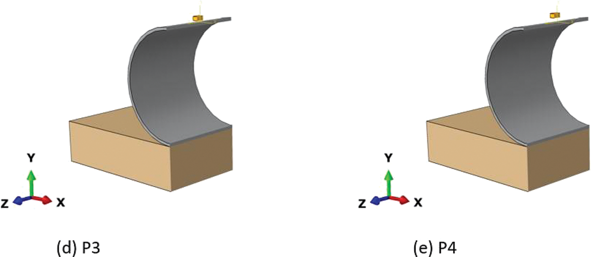
Figure 5: Different locations of the TNT
The CEL-FEM [67] is a robust numerical technique employed for blast simulation in Abaqus, a widely used software for finite element analysis. This method integrates the benefits of both Eulerian and Lagrangian formulations to replicate the intricate dynamics between the blast wave and the analysed structure precisely.
In this investigation, we employed the Eulerian-Lagrangian methodology coupled with the Finite Element Method (CEL-FEM) within the framework of Abaqus [67] to replicate blast effects on structural elements. This approach integrates two distinct mesh types: Eulerian and Lagrangian. The Eulerian mesh serves to depict the ambient air or fluid medium traversed by the blast wave, maintaining a fixed position while governing the fluid dynamics of the blast. It establishes pressure and velocity constraints on the Lagrangian mesh, which, in turn, represents the structure or object undergoing the blast, conforming to its deformation. By imposing pressure and velocity parameters from the Eulerian mesh onto the Lagrangian counterpart, the CEL-FEM technique enables an authentic emulation of blast effects on the structure, capturing intricate deformations and stresses engendered by the blast wave.
Contrasted with semi-empirical methodologies like the ConWep Blast Code [67], the Eulerian-Lagrangian approach conjoined with the Finite Element Method (CEL-FEM) offers notable advantages. Primarily, CEL-FEM ensures heightened precision in simulating blast effects by directly resolving the governing equations of fluid dynamics and structural mechanics, thereby affording a more nuanced and accurate portrayal of blast wave propagation and structural response. Furthermore, CEL-FEM boasts enhanced versatility in modeling intricate geometries and material properties, facilitating precise simulations of blasts on irregular structures and heterogeneous materials. Moreover, CEL-FEM facilitates a comprehensive analysis of blast effects, including meticulous scrutiny of structural deformations, stresses, and failure mechanisms. Finally, CEL-FEM simulations stand poised for validation against experimental data, bolstering the credibility of the analysis and instilling confidence in the fidelity of the results. Ultimately, this comparison finds support in the following reference [68], which unequivocally demonstrate that CEL-FEM represents a more realistic and accurate approach for simulating explosion events and predicting the response of infrastructure elements.
4.3 Johnson-Cook Plasticity Model
The widely-used Johnson-Cook plasticity model [67] in Abaqus facilitates the representation of material behavior under elevated temperatures and high strain rates. It proves valuable in simulating steel pipelines subjected to internal pressure and external loads, allowing engineers to predict deformation and failure accurately across various loading conditions. By integrating the Johnson-Cook plasticity model into Abaqus, engineers ensure precise predictions through finite element analysis.
The Johnson-Cook plasticity model considers plastic deformation in materials, factoring in strain hardening, strain rate sensitivity, and thermal softening, to predict material behavior under mechanical loading [67]. It facilitates precise understanding and prediction of steel pipeline performance in applications such as oil and gas transportation and structural usage by accounting for these factors. When integrated with appropriate failure criteria like the Johnson-Cook damage model, it enables forecasting of damage initiation and progression in pipelines, aiding engineers in assessing structural integrity and preventing catastrophic failures.
The model defines equivalent Von Mises flow stress as [67]:
This study has implemented a dynamic increase coefficient of 1.24 for steel, sourced from UFC 3-340-02 (2008) [69], to appropriately consider the effects of strain rate.
The ideal gas equation of state, a fundamental concept in thermodynamics, holds great importance in engineering simulations, particularly for modeling air. Abaqus, a widely-used software for finite element analysis, offers a feature enabling the incorporation of this equation into simulations. This equation establishes the relationship between a gas’s pressure, volume, and temperature [67], assuming ideal gas behavior where gas molecules do not interact. This simplifies modeling and facilitates straightforward calculations and predictions. Implementing the ideal gas equation of state in Abaqus requires defining the gas as ideal and specifying appropriate material properties [67]. The equation is expressed as follows:
The Equation of State (EOS) values utilized are provided in the referenced source [20]. Abaqus software provides a wide array of pre-defined materials, including air, which can be customized for specific simulations. By incorporating the behavior of an ideal gas and specifying relevant thermodynamic properties like specific heat capacity and gas constant, engineers and researchers can effectively model and analyze air characteristics in various applications. This enables accurate predictions of air responses under different conditions, such as changes in pressure, temperature, or volume.
4.5 Jones-Wilkins-Lee EOS for TNT
The JWL Equation of State (EOS), devised by Jones, Wilkins, and Lee, is a widely employed model for explosive simulation, particularly for TNT explosives common in military and industrial applications. Integrated into Abaqus software, it provides engineers and researchers with a comprehensive understanding of explosive behavior under varying conditions. By incorporating critical parameters like pressure, temperature, and volume, the JWL EOS enables the accurate prediction of explosive response to mechanical stimuli. This facilitates the construction of detailed models and simulation of explosive materials’ performance, aiding in the design of protective structures and enhancing safety in explosive-related industries. Utilizing the JWL EOS equation, engineers can calculate blast pressures resulting from TNT detonation, crucial for analyzing blast effects and ensuring safety protocols [67].
In this context, “P” represents the hydrostatic pressure, while A, B, R1, R2, and
4.6 Mohr Coulomb Plasticity (MCP) Model for Soil Mass
The current study utilised the MCP criterion, as provided in Abaqus [67], to characterise soil behavior, which is expressed mathematically as:
Referring to Eq. (4), the critical shear stress, denoted as
When integrating a steel pipeline in Abaqus, careful selection of finite element type and size is crucial for precise and dependable outcomes [67]. The type of finite element chosen determines the mathematical model used to simulate the pipeline’s behavior under varying load conditions, considering steel’s nonlinear behavior and resistance to deformation. Commonly employed element types include shell, beam, and solid elements, each with its advantages and limitations. Conversely, the size of finite elements involves breaking down the pipeline into smaller segments, impacting both precision and computational efficiency. While smaller segments offer a detailed depiction of the pipeline’s characteristics, they increase computational expenses, whereas larger segments reduce computation time but may compromise accuracy [67]. Balancing accuracy and computational efficiency requires considering factors such as pipeline geometry complexity, anticipated loading conditions, and desired precision level. Sensitivity analyses using different element types and sizes can aid in determining the optimal meshing strategy for the specific steel pipeline under investigation.
This study involves using a Lagrange mesh to simulate the steel pipe. In this mesh, the coordinates are dynamic and move along with the material. Conversely, the air and high explosive are simulated using an Euler mesh, where the grid remains fixed and the material flows through it. The interaction between these two meshes takes place at the Euler-Lagrange interface. The Lagrange mesh applies a geometric restriction to the Euler mesh, while the Euler mesh functions as a pressure boundary for the Lagrange mesh. Thus, to establish the boundary condition for the Euler mesh, it is designated as an outflow boundary.
The C3D8R component in Abaqus is extensively utilised for meshing steel pipelines. This component, an eight-node linear brick element, is suitable for both solid and shell modelling. It proves particularly beneficial for modeling structures that experience significant deformations and possess intricate material characteristics, like steel pipelines. The C3D8R element accurately portrays stress and strain distributions within the pipeline, which is crucial for evaluating its structural integrity. By incorporating this element into the meshing process, engineers can obtain reliable outcomes and make well-informed decisions regarding the design and performance of steel pipelines. C3D8R has meshed various mediums, including pipes, air, TNT, and soil.
When it comes to incorporating the Eulerian domain into Abaqus, one commonly utilised element type is the EC3D8R element. This linear brick element has eight nodes in a three-dimensional space, making it ideal for modeling solid structures. The EC3D8R element provides high accuracy and stability when capturing the behaviour of materials under different loading conditions. It can represent both linear and nonlinear material behavior, making it a versatile option for simulating intricate scenarios. By choosing the EC3D8R element for meshing the Eulerian domain, engineers can ensure precise and dependable results in their Abaqus simulations.
5 Numerical Validation and Mesh Refinement
Validating numerical results in Abaqus is crucial for ensuring the accuracy and reliability of simulations. This involves comparing numerical predictions with experimental or analytical data to evaluate model performance and identify discrepancies. Techniques such as sensitivity analysis, convergence study, and error estimation are utilized for validation, enhancing the credibility of findings and ensuring design reliability.
Sensitivity analysis, also known as mesh refinement, is crucial for verifying numerical models, especially in computational engineering. Here, the aim is to validate a steel pipeline model using Abaqus software. One approach involves adjusting finite element sizes within the model to assess sensitivity to these changes. Analyzing the outcomes helps refine the model’s accuracy in replicating real-world behavior. This analysis instills confidence in the model’s reliability and predictive capabilities, essential for engineering applications.
Due to the absence of reported data in the reference experimental study [20], default pipe-soil interactions in the Abaqus were utilized. It is important to note that in the reference study [20], the pipeline is depicted as resting on the soil rather than being buried within it. Therefore, consistency with this scenario was maintained to validate the numerical findings, without considering additional surcharge and other loads.
The examination of mesh sensitivity was conducted using a steel tube, as illustrated in Fig. 6, and various mesh dimensions ranging from 6.55 mm (t/4) to 26.2 mm (t), where “t” represents the thickness of the tube wall. The simulated tube was subjected to a TNT explosion with a mass of 0.40 kg, aligning with the investigation by Song et al. [20]. The results of the mesh sensitivity analysis are presented in Table 1, encompassing the highest distortion for each mesh dimension. The maximum deformation increased as the element’s size decreased, as observed. Specifically, the 6.55 mm mesh size showed a maximum deformation of 34.41 mm, 1.68% lower than the experimental data. On the other hand, the 26.2 mm mesh size exhibited a deformation of 31.67 mm, which was 9.51% lower than the experimental data [20].
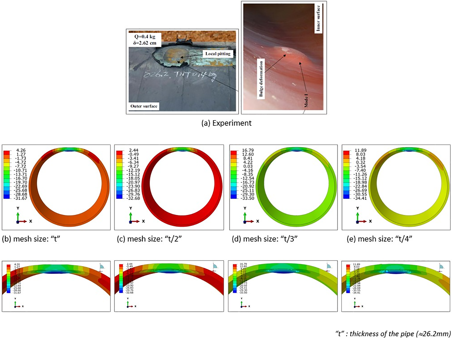
Figure 6: Deformation (mm) of the pipe: numerical validation
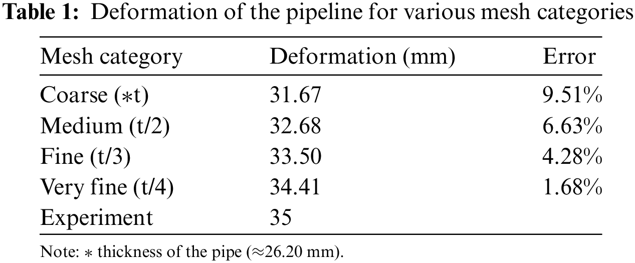
Additionally, the 8.73 mm (t/3) mesh and the 13.1 mm (t/2) mesh resulted in deformations of 33.50 mm (4.28% lower than the experimental data) and 32.68 mm (6.63% lower than the experimental data), respectively. Due to its small deformation error (1.68%), the 6.55 mm mesh size was considered suitable for analysing the pipe’s behaviour under blast loading. It was utilised for the parametric analysis presented in this paper.
The observed increase in maximum deformation with decreasing mesh size is due to the finer resolution afforded by smaller elements. Smaller mesh dimensions allow for a more detailed simulation of the structural response to the blast, capturing localized deformations and stress concentrations within the steel tube more accurately. Consequently, smaller mesh sizes result in higher deformation values, reflecting the nuances of the tube’s response to the TNT explosion. However, the disparity between simulated and experimental deformation values can be attributed to the trade-off involved in mesh refinement. While smaller mesh sizes offer improved accuracy, they also necessitate greater computational resources, leading to longer execution times and increased storage requirements.
In Fig. 6, it is noteworthy to highlight that the computer simulation exhibits minor disparities between the anticipated outcomes and the actual experimental data due to several factors taken into account: firstly, the idealization of boundary conditions, default interactions, constraints, and material modeling; and secondly, the omission of weather effects such as wind, temperature, and humidity.
Acknowledging the limitation arising from the scarcity of experimental studies specifically focusing on pipelines under blast loading, and the lack of experimental data specifically pertaining to pipeline behavior under blast loading, compelled the reliance solely on available or reported results from the reference experimental study for comparison.
The standoff distance refers to the minimum proximity between the detonation point (precisely, the centroid of the brick TNT) and the specific location of concern along the pipeline. In this context, two distinct standoff distances are under consideration: 25 and 50 mm in Fig. 7. Upon examining Table 1, it becomes apparent that the maximum displacement of the pipe diminishes as the standoff distance increases.
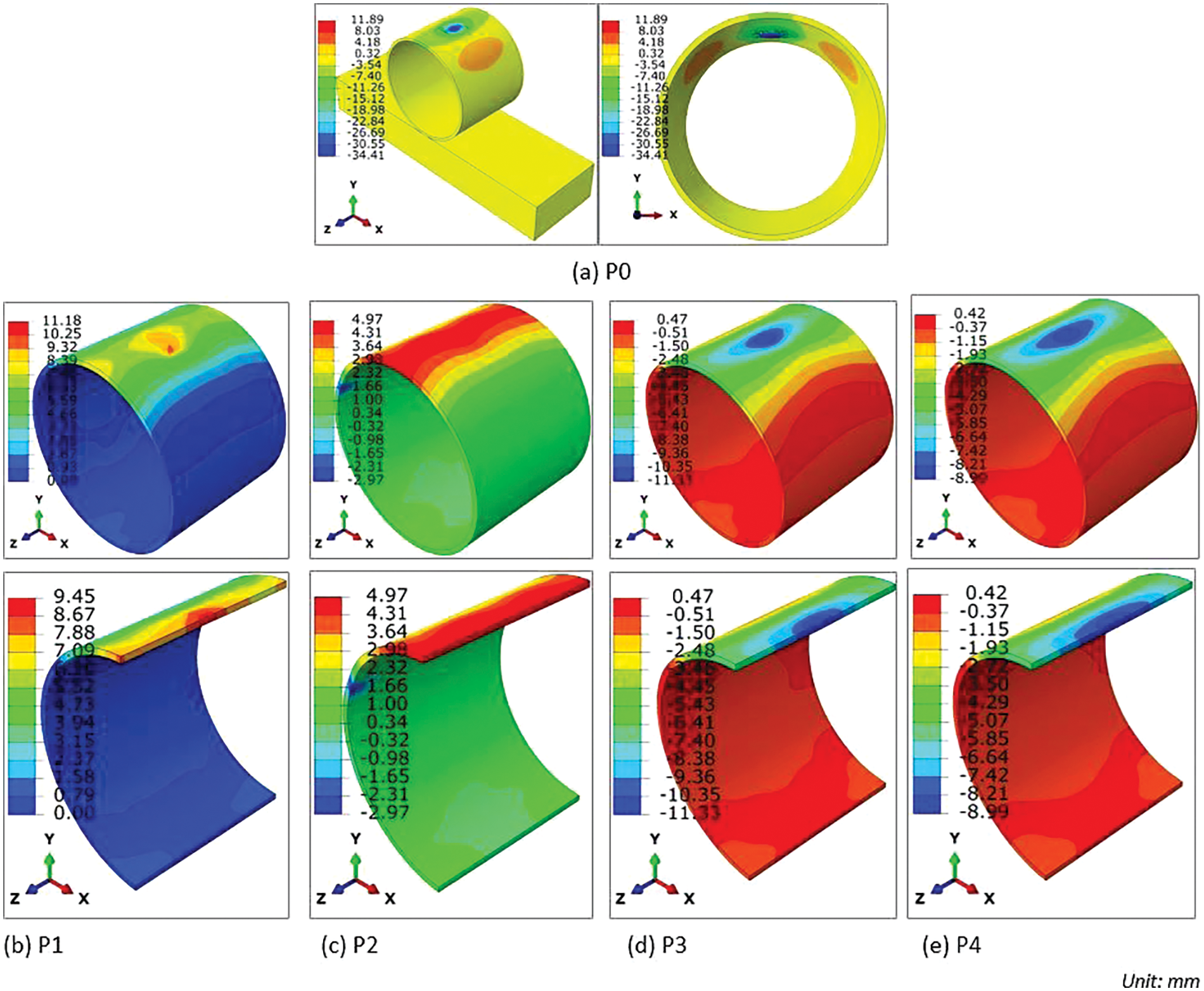
Figure 7: The pipe’s deformation (mm) under different locations of TNT with the same mass (0.40 kg)
The observed trend in Table 1, where the maximum displacement of the pipe decreases with increasing standoff distance, is indicative of the attenuation of blast wave energy as it propagates away from the detonation point. When the detonation point is closer to the pipeline (at a smaller standoff distance, such as 25 mm), the blast wave reaches the pipeline with higher energy, causing more significant deformation. However, as the standoff distance increases to 50 mm, the blast wave energy is distributed over a larger area, resulting in reduced intensity upon reaching the pipeline. Consequently, the magnitude of deformation and displacement decreases as the standoff distance increases. This highlights the importance of considering standoff distance in blast mitigation strategies for underground pipelines, as greater distances can help mitigate the impact of blast waves on pipeline integrity.
The simulated outcomes demonstrate that the position of the TNT relative to the mid-span section of the pipe significantly affects deformation patterns. When the TNT contacts the exterior surface at the mid-span section, it induces a downward displacement, resulting in an ultimate deflection of 34.41 mm. Conversely, positioning the TNT below the midpoint leads to upward deflection, with deflections of 9.45 and 4.97 mm observed at distances of 25 and 50 mm below, respectively. When placed above the midpoint, the TNT generates a downward force, causing localized deformation in the form of punching and pitting on the exterior surface, resulting in maximum downward displacements of 11.33 and 8.99 mm at distances of 25 and 50 mm above, respectively. These findings underscore the importance of considering the precise position of explosive charges relative to structural elements in predicting and mitigating blast-induced deformations in underground pipelines.
Conversely, in scenarios where the TNT remains non-contact, the deformation is dispersed across a broader expanse, appearing as denting and bulging deformations. This shift in the mode of failure can be attributed to the wider propagation of the incident compression waves through the upper thickness of the pipe, subsequently reflecting from the distal end as high tensile stress waves. This propagation enables the transfer of blast energy over a larger area, resulting in lateral diametric deformation in conjunction with the vertical deformation of the pipe, as opposed to the localised effect observed with TNT contact. The correlation between the displacement pattern observed on the upper exterior of the conduit and the displacement distribution within the unidirectional slab during explosive blasts is conspicuously apparent. Notably, the deformation propagation predominantly extends widthwise relative to the length of the TNT brick, owing to the influence of the pipe’s boundary conditions and reflections from the brick’s lateral faces. This phenomenon results in a heightened dissemination of explosive energy along the longitudinal axis of the conduit compared to its lateral diametric orientation. The broader propagation of compression waves through the pipe’s upper thickness and subsequent reflection as high tensile stress waves play a crucial role in the observed denting and bulging deformations. This mechanism underscores the importance of considering blast wave propagation dynamics and boundary conditions in understanding the deformation patterns observed in underground pipelines subjected to non-contact explosive blasts.
The analysis reveals that as the standoff distance increases, there is a reduction in the extent of pipe deformation. However, it is noteworthy that the nature of pipe deformation differs significantly depending on whether the explosion occurs above or below its top surface. This observed variation can be attributed to the differing mechanisms by which explosion energy is transferred. In instances where explosions originate below the pipe, energy disperses both laterally and vertically, resulting in a combination of diametric and vertical deformations. Conversely, when explosions take place above the pipe, energy tends to localize, leading predominantly to a mode of failure characterized by punching or denting. This distinction in energy distribution mechanisms elucidates the contrasting deformation patterns observed in our study and underscores the importance of considering explosion location when assessing the structural response of pipelines to blast events.
Referring to Fig. 8, the observed variations in stress distributions across different blast scenarios can be attributed to the differing mechanisms of energy transfer and interaction between the explosive force and the pipe structure. In the case of direct contact explosions (P0), the rapid transfer of energy from the explosion to the pipe results in a significant and immediate compression, leading to the observed peak principal compressive stress of 849.66 megapascals (MPa) at 0.94 milliseconds. Subsequently, as the explosive force propagates through the pipe, it induces a tensile stress of 403.58 MPa at 3 milliseconds. Conversely, in scenarios involving non-contact subsurface detonations (P1 and P2), the explosive force encounters the pipe at a distance, causing a delayed but still substantial compression. This delayed compression leads to a peak compressive stress of 415.77 MPa at 0.90 milliseconds for P1 and 189.26 MPa at 2.88 milliseconds for P2. The tensile stresses observed at earlier time points (0.40 milliseconds for P1 and 0.51 milliseconds for P2) are indicative of the initial flexural response of the pipe to the blast wave. Similarly, in non-contact above-surface blasts (P3 and P4), the explosive force applies pressure from above, resulting in an initial compression followed by stress reversals. This mechanism is evidenced by the peak compressive stress of 850.99 MPa at 0.21 milliseconds for P3 and 932.57 MPa at 0.315 milliseconds for P4, with corresponding tensile stresses occurring at later time points (1.097 milliseconds for P3 and 2.16 milliseconds for P4). Notably, in instances denoted by P0, P1, and P2, the compressive stress exceeds the yield strength threshold of the pipeline, highlighting the critical implications of blast loading on structural integrity.
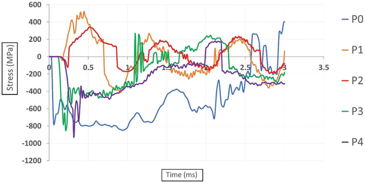
Figure 8: Principal stress time plots at the location of maximum deformation
The observed differences in peak shear stress values across various blast scenarios can be attributed to the differing mechanisms of blast propagation and interaction with the pipeline structure in Fig. 9. In the case of the contact blast (P0), the explosive force directly impinges upon the pipe’s surface, leading to rapid and intense stress transmission through the material. Consequently, this results in a higher peak shear stress of 721.12 MPa at 0.94 ms. Conversely, in scenarios involving non-contact subsurface blasts, such as P1 and P2, the TNT charge detonated beneath the pipe induces stress waves that propagate upwards, interacting with the underside of the pipe. The distance between the explosive charge and the pipe significantly influences the amplitude and timing of stress peaks, with the 25 mm depth (P1) exhibiting a maximal shear stress of 458.51 MPa at 0.46 ms, and the 50 mm depth (P2) resulting in a peak stress of 299.66 MPa at 0.51 ms. Similarly, in instances of non-contact above-surface blasts, as seen in P3 and P4, the explosive force interacts with the upper surface of the pipe, generating stress waves that propagate downwards. The elevation of the explosive charge above the pipe determines the intensity and timing of stress peaks, with the 25 mm elevation (P3) inducing a maximal stress of 474.65 MPa at 0.22 ms, while the 50 mm elevation (P4) yields a peak shear stress of 463.21 MPa at 0.33 ms. These findings underscore the intricate interplay between blast characteristics, such as proximity and orientation, and their effects on the structural response of underground pipelines, providing valuable insights for designing resilient infrastructure against blast events.
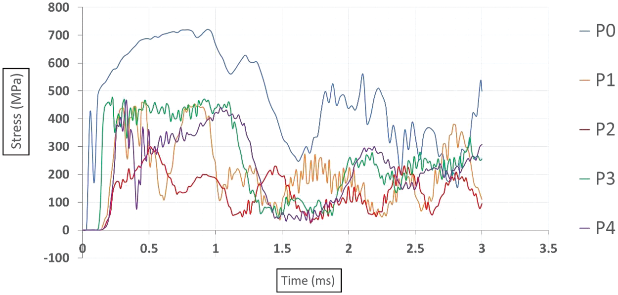
Figure 9: Shear stress time plots at the location of maximum deformation
The observed variations in peak vertical acceleration of the pipe, as depicted in Fig. 10, are attributed to the positioning of the TNT detonation point relative to the pipe’s upper thickness at the mid-span section. When the TNT is detonated directly at the midpoint of the pipe’s upper thickness (P0), the resulting peak acceleration reaches a remarkable 601.47 times the force of gravity (601.47 g). Placing the TNT 25 mm below this midpoint (P1) results in a reduced peak acceleration of 187.25 g, while positioning it 50 mm below (P2) further decreases the maximum acceleration to 72.54 g, reflecting a 61.26% reduction compared to P1. Conversely, positioning the TNT 25 mm above the midpoint (P3) leads to a substantially higher peak acceleration of 404.80 g, with placement 50 mm above (P4) resulting in a maximum acceleration of 258.57 g. It is noteworthy that detonations above the surface (P3 and P4) induce higher accelerations compared to sub-surface detonations (P1 and P2). This disparity arises from the complex interaction between the blast wave and the pipe structure. In sub-surface blast scenarios, the energy released by the explosion not only causes vertical deformation but also induces diametric deformation, resulting in a comparatively lower peak acceleration. Conversely, in above-surface detonations, the blast wave directly impacts the pipe structure, leading to higher acceleration due to the concentrated energy transfer. These findings elucidate the nuanced mechanisms influencing pipe response to blast loading and underscore the importance of precise positioning in mitigating blast-induced damage.
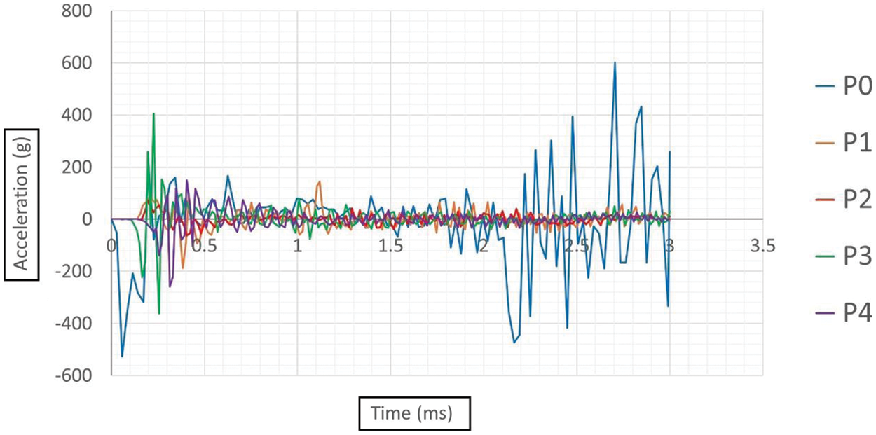
Figure 10: Acceleration time plots at the location of maximum deformation
Fig. 11 illustrates the temporal evolution of plastic dissipation energy (PDE) across various blast scenarios analyzed in this study. Among these scenarios, the highest PDE is recorded during a contact blast (P0), reaching 119.51 J. Conversely, subsurface blast scenarios (P1 and P2) exhibit maximum PDE values of 28.75 and 17.64 J, respectively, while above-surface blast scenarios (P3 and P4) demonstrate lower maximum PDE values of 21.61 and 11.56 J, respectively. This discrepancy arises from the distinct mechanisms underlying subsurface and above-surface blasts. Subsurface blasts subject the pipe to both vertical and lateral diametric deformations, resulting in higher PDE values as the pipe undergoes significant plastic deformation to accommodate the combined stresses. In contrast, above-surface blasts primarily induce lateral deformation, leading to comparatively lower PDE values as the pipe experiences less severe plastic deformation. Therefore, the observed differences in PDE values across blast scenarios can be attributed to the varying deformation mechanisms induced by the blast types, highlighting the significance of blast characteristics in determining the extent of plastic dissipation energy in underground pipelines.
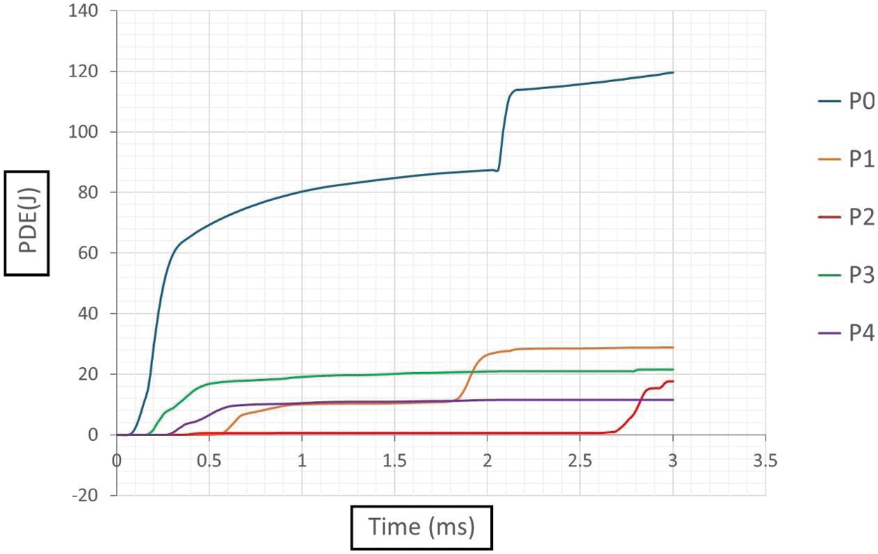
Figure 11: Plastic dissipation energy (PDE) plots
Fig. 12 illustrates the temporal evolution of pressure at the point of maximal deformation across various blast scenarios examined in our study. Initially, when the TNT charge is in direct contact with the pipe (position P0), the resultant reflected pressure at the point of maximal deformation peaks at 2.88 MPa. However, relocating the TNT charge to positions P1 (subsurface blast at 25 mm) and P2 (subsurface blast at 50 mm) leads to a notable decrease in reflected pressure, reducing it to 0.84 and 0.42 MPa, respectively. Conversely, shifting the TNT position from P0 (contact blast) to positions P3 (above-surface blast at 25 mm) and P4 (above-surface blast at 50 mm) results in a decrease in reflected pressure from 2.88 to 1.01 MPa and 0.89 MPa, respectively. This observed decrease in reflected pressure in subsurface blasts compared to above-surface blasts can be attributed to the dispersion of energy through vertical deformation and lateral diametric deformation. Subsurface blasts induce a broader distribution of forces, dissipating energy more effectively through lateral expansion and vertical displacement. In contrast, above-surface blasts tend to exhibit localized deformation, concentrating energy in a smaller area and resulting in more significant overall deformation compared to subsurface blasts. These mechanisms elucidate the variations in reflected pressure observed across different blast scenarios, highlighting the importance of blast positioning and depth in influencing the structural response of underground pipelines.
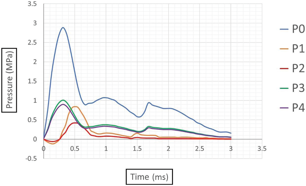
Figure 12: Pressure time plots for different blast cases
6.6 Explosive-Air Velocity Field
In this section, we elucidated the intricate distribution of explosive-air velocity within the Eulerian domain enveloping a steel pipe under examination in three discrete blast scenarios: contact blast, below-surface blast, and above-surface blast in Figs. 13–18. The velocity component selected in Abaqus is V2, i.e., in Y-direction. Each scenario denotes a unique positioning of TNT in relation to the pipe, thereby exerting distinct influences on the propagation of the blast wave and ensuing airflow dynamics. For instance, in the contact blast scenario (P0), the detonation of TNT directly atop the pipe’s upper surface initiates a shock wave that swiftly expands outward, engendering zones of elevated pressure that impel the adjacent air mass forward with notable celerity. As the incident blast wave reaches the surface of the pipe, the negative component of the velocity increases over time. Subsequently, as the wave propagates through the pipe and is reflected back as a high tensile stress wave, the negative component begins to decrease, while the positive component commences an upward trend with time. This temporal evolution indicates that following the permanent deformation inflicted upon the pipe by the incident and reflected waves, the explosive medium expands into the surrounding air domain with escalating velocity. Moreover, as time progresses, these intricate airflow dynamics culminate in the emergence of a mushroom-type cloud, characteristic of explosive events in Figs. 13 and 14. Conversely, in the below-surface blast scenario (P1), the detonation occurring beneath the pipe engenders a complex interplay between the blast wave and the ground, yielding diverse pressure gradients and airflow patterns in Figs. 15 and 16. Likewise, the above-surface blast scenario (P3), typified by TNT detonation positioned above the pipe, engenders a distinct distribution of pressure waves that interact with both the pipe and the surrounding air, thereby provoking turbulent flow phenomena and the formation of eddies in Figs. 17 and 18. Figs. 13–18 serve as graphical depictions of these phenomena across various temporal intervals, furnishing invaluable insights into the dynamic responses of the air medium to explosive loading and the consequent implications for structural integrity and strategies for blast mitigation.
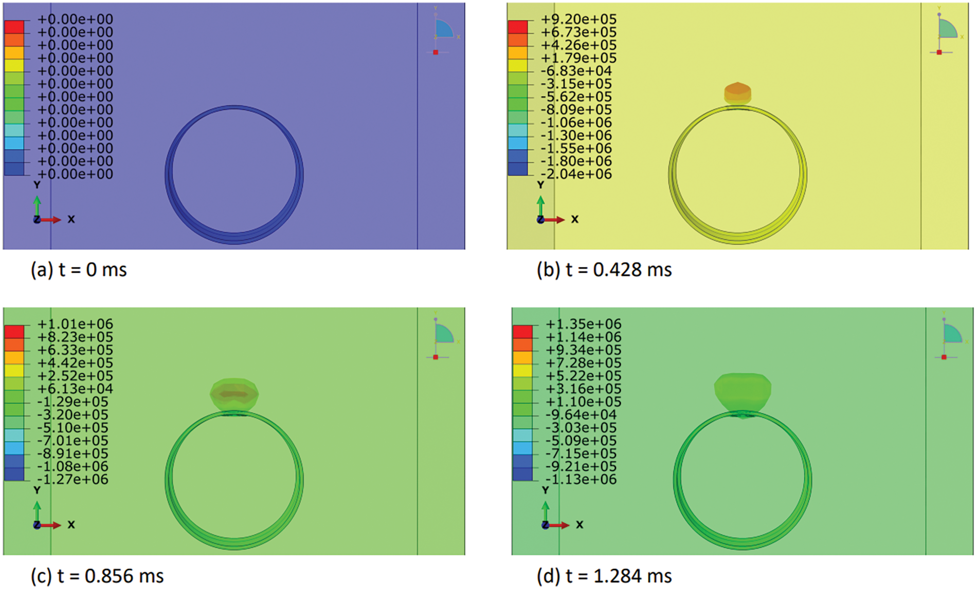
Figure 13: Explosive-air velocity (mm/sec) distribution under contact blast scenario (P0): Part I
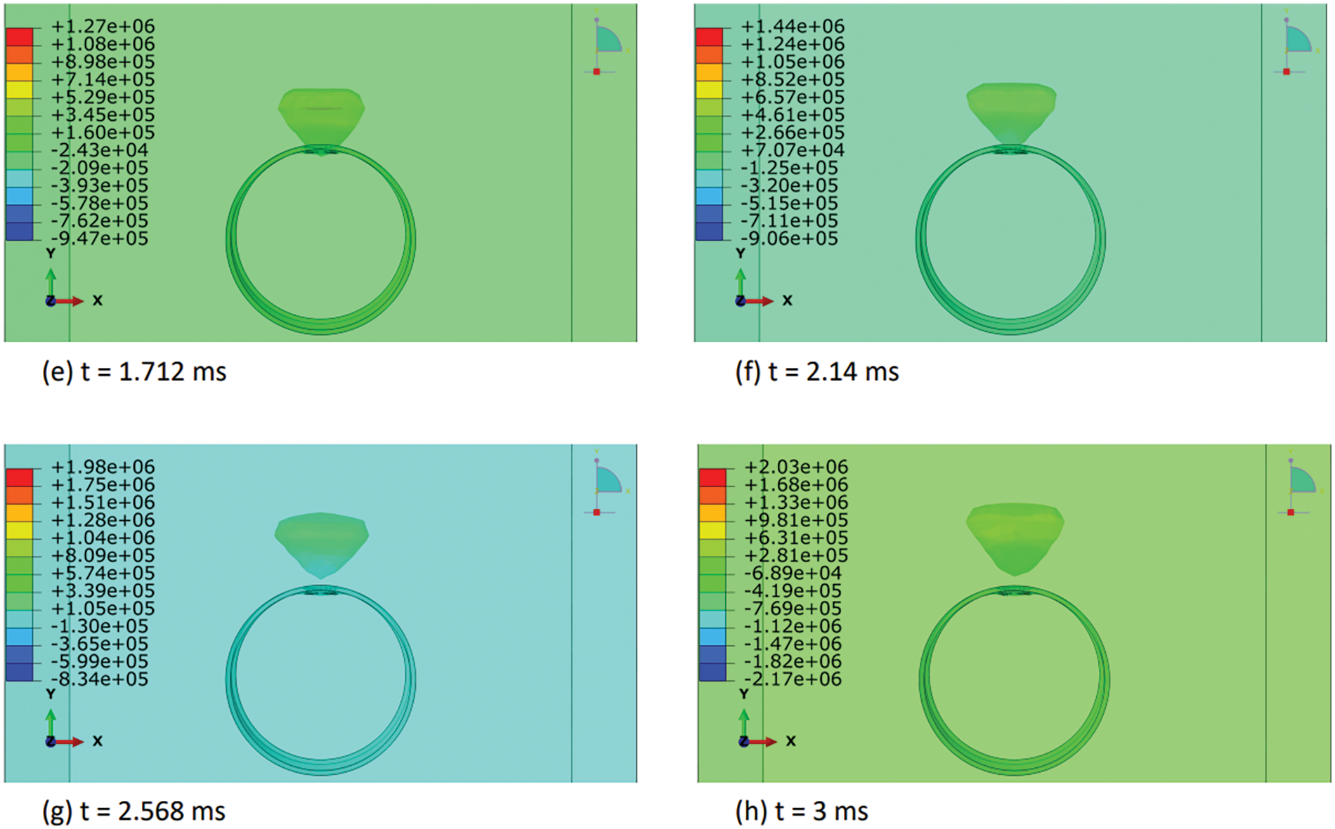
Figure 14: Explosive-air velocity (mm/sec) distribution under contact blast scenario (P0): Part II
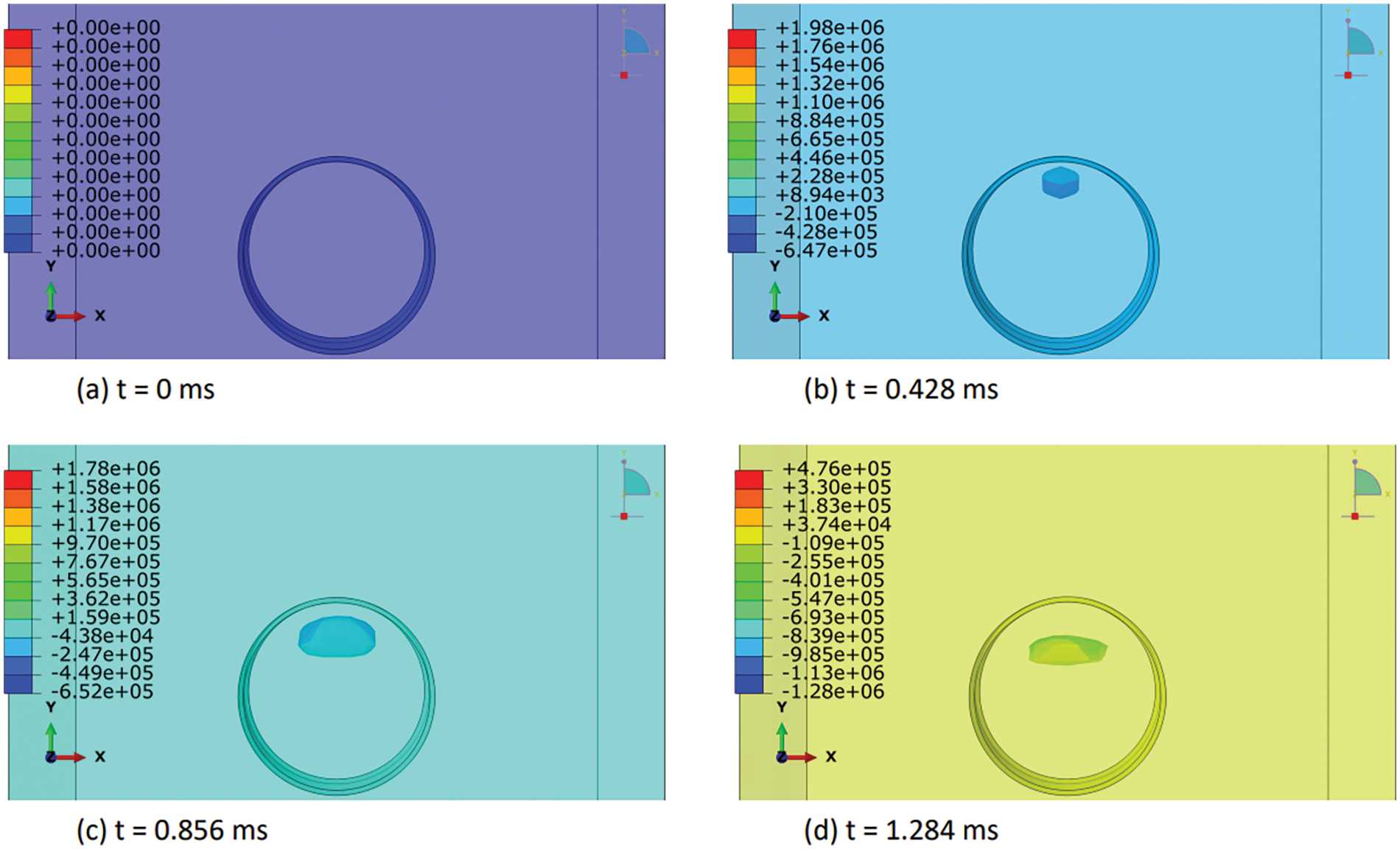
Figure 15: Explosive-air velocity (mm/sec) distribution under below-surface blast (P1): Part I
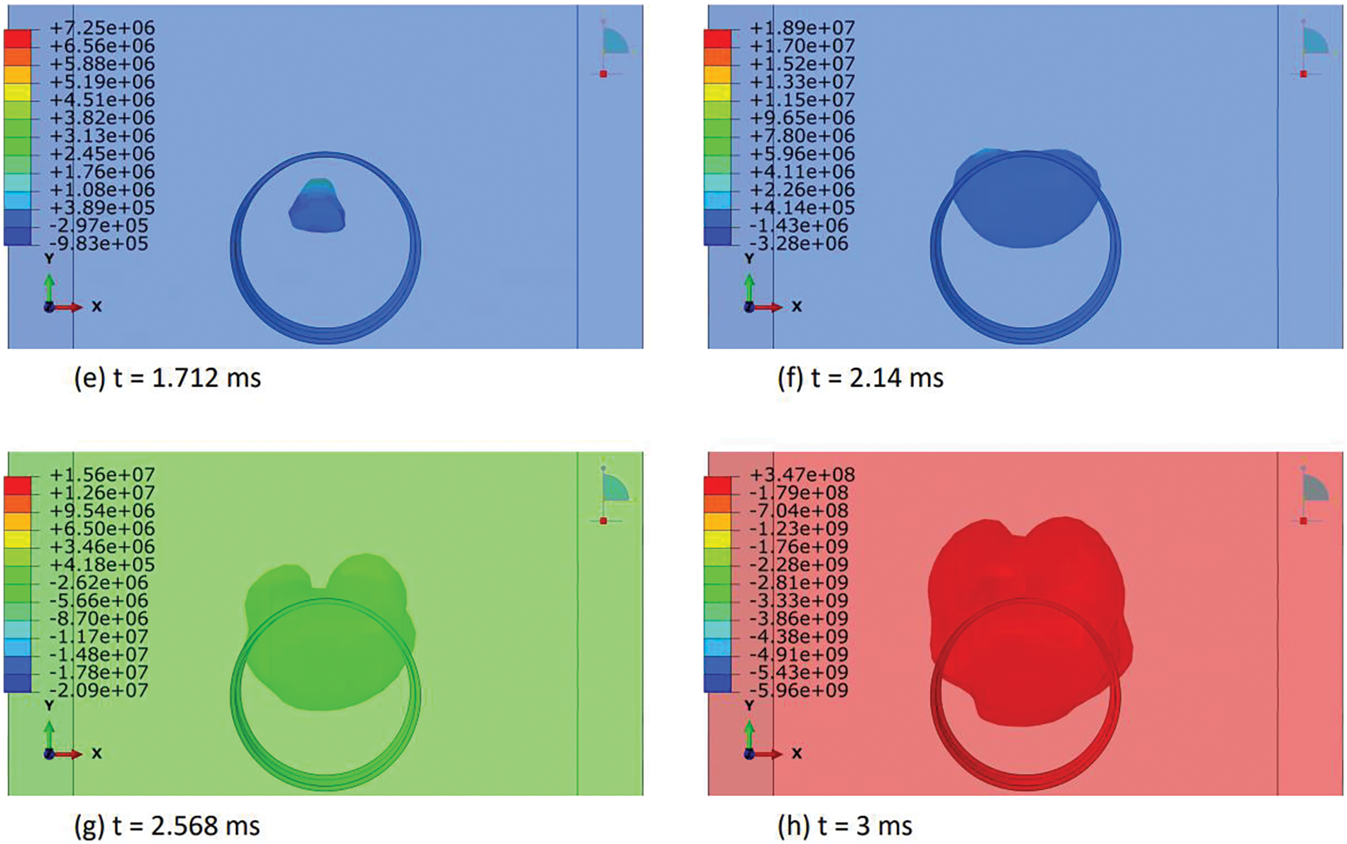
Figure 16: Explosive-air velocity (mm/sec) distribution under below-surface blast (P1): Part II
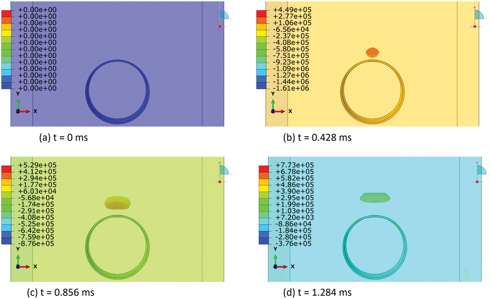
Figure 17: Explosive-air velocity (mm/sec) distribution under above-surface blast (P3): Part I
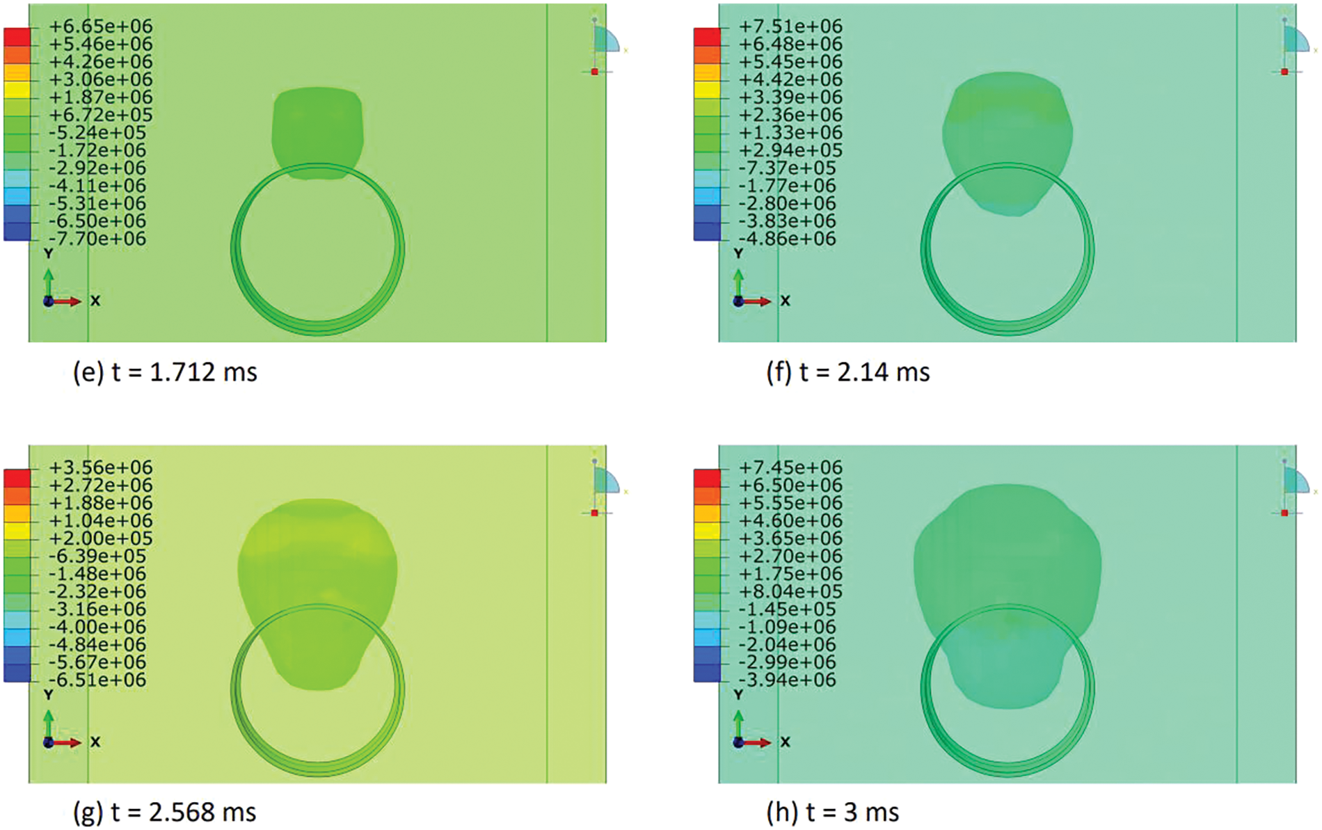
Figure 18: Explosive-air velocity (mm/sec) distribution under above-surface blast (P3): Part II
This study successfully validated an empty pipe model under contact blast conditions utilising the ABAQUS software, known for its efficacy in simulating and analysing blast effects on buried pipelines within the realm of mechanical engineering. We meticulously examined the repercussions of above-surface and below-surface blasts at standoff distances of 25 and 50 mm through a coupled Eulerian-Lagrangian computational fluid dynamics approach. Our investigation relied on the default mechanical models provided by ABAQUS, facilitating a comprehensive comparison and discussion of the relative performance of the pipe models.
The observed decrease in pipe deformation with increased explosion-to-pipe distance can be attributed to the dissipation of energy and attenuation of stress waves as they propagate through the pipe structure. Notably, the differing deformation patterns between contact and non-contact explosions highlight the role of wave propagation dynamics in shaping the extent and nature of structural damage.
Furthermore, the distinct energy transfer mechanisms identified in the subsurface and above-surface blasts underscore the importance of blast positioning relative to the pipeline surface. Subsurface blasts disperse energy laterally and vertically, resulting in a combination of diametric and vertical deformations, whereas above-surface blasts exhibit predominantly localized deformation due to the concentrated energy release. These findings suggest that blast-induced deformations are influenced by both the direction and intensity of energy propagation within the pipeline structure.
The analysis of plastic dissipation energy provides additional insights into the energy-absorbing capacity of the pipeline material, with subsurface blasts exhibiting higher dissipation values attributed to the combined vertical and lateral diametric deformations. This highlights the significance of material properties and structural design in mitigating blast-induced damage and ensuring pipeline integrity.
The investigated blast scenarios exhibit varying ratios of plastic damage with respect to the contact blast (P0). P1 and P2 demonstrate approximately 24.07% and 14.77% of P0’s PDE, respectively, while P3 and P4 show lower PDE values, accounting for about 18.08% and 9.67% of P0’s PDE, respectively. The severity order of the plastic dissipation energy (PDE), from highest to lowest, based on the PDE ratios compared to P0, is: P0 (contact blast), P1 (subsurface blast at 25 mm), P3 (above surface blast at 25 mm), P2 (subsurface blast at 50 mm), and P4 (above surface blast at 50 mm).
Lastly, the observed variation in reflected pressures between subsurface and above-surface blasts underscores the effectiveness of altering TNT position relative to the pipe surface in mitigating blast effects. Subsurface blasts result in significantly reduced reflected pressures compared to above-surface blasts, indicating a more efficient dispersion of energy through lateral diametric deformation.
Overall, our comprehensive investigation sheds light on the complex dynamics of blast effects on buried pipelines and underscores the critical role of blast positioning, energy propagation, and material properties in determining structural response. These insights are invaluable for enhancing pipeline resilience and informing blast mitigation strategies in diverse industrial contexts. Further research in this area could explore more sophisticated numerical modeling techniques and experimental validations to refine our understanding of blast-induced phenomena and optimize pipeline design and maintenance practices.
Limitations: The absence of advanced explosion testing facilities has indeed catalyzed a wave of innovation among researchers, driving them to explore alternative avenues to understand and predict the effects of explosions on structures. While it is true that this limitation poses challenges, it has also acted as a catalyst for creativity and ingenuity within the research community. In the face of this constraint, researchers and students alike have harnessed their expertise to advance analytical methods and computational simulations to unprecedented levels.
One notable outcome of this limitation is the heightened reliance on existing software tools, which has paradoxically fueled innovation in the field. Researchers have been compelled to push the boundaries of these tools, seeking to refine and develop advanced models and simulations that more accurately depict the intricate behavior of structures subjected to explosive forces. This concerted effort has not only led to significant advancements in simulation technology but has also fostered a culture of collaboration and knowledge exchange among researchers worldwide.
Indeed, the use of simulation tools has facilitated unprecedented levels of collaboration, allowing researchers from diverse backgrounds and geographic locations to pool their expertise and resources. This collaborative approach has proven instrumental in accelerating progress in understanding structural responses to explosions. By sharing data, methodologies, and insights, researchers have collectively propelled the field forward, leading to a deeper understanding of the complex dynamics at play during explosive events.
However, despite the remarkable progress achieved through computational simulations, it is crucial to acknowledge the inherent limitations of these models. While our simulations demonstrate good agreement with available experimental data, it is important to recognize that they may not comprehensively encompass all real-world intricacies. Factors such as fire and weather effects, as well as surcharge load, were not explicitly incorporated into our analysis due to the lack of sufficient experimental data from the referenced study [20].
Furthermore, the absence of state-of-the-art explosion testing laboratories presents a significant challenge in validating our simulation results against real-world scenarios. This limitation is compounded by various constraints associated with traditional explosion testing methods, including heavy costs, safety hazards, and logistical complexities. The high cost of establishing and maintaining such facilities, coupled with the inherent risks posed by explosive testing, makes it impractical for many research institutions to invest in these resources. Additionally, the stringent safety regulations and ethical considerations surrounding explosive testing impose further limitations on its feasibility and accessibility.
While computational models offer valuable insights, their predictive capabilities are inherently limited by the accuracy and comprehensiveness of the underlying models and data inputs. As such, it is imperative that future research efforts aim to address these limitations by incorporating additional factors and refining simulation techniques to enhance the fidelity and reliability of computational models in simulating explosion dynamics.
Scope for Future Research: In this study, the authors have explored the response of an empty pipeline under various blast scenarios. Looking ahead, there is a significant opportunity for further investigation into pipeline response when filled with fluid. However, it is essential to note that the current literature lacks adequate modeling parameters to accurately represent fluid dynamics within the pipeline. This presents a challenging yet crucial task for future research endeavors. Nevertheless, addressing this gap could provide valuable insights into the behavior of fluid-filled pipelines under blast conditions, facilitating the development of more comprehensive safety measures and maintenance strategies.
Additionally, the study recommends the utilization of energy-absorbing materials such as thin coatings of ultra-high-strength concrete, metallic foams, CFRP wraps, and others to effectively mitigate blast damage. However, further research is warranted to delve into the specifics of material selection, application methods, and cost-effectiveness. By addressing these aspects, future studies can provide practical guidance for implementing such measures in real-world scenarios, thereby enhancing the resilience and safety of underground pipelines against blast events.
Acknowledgement: Not applicable.
Funding Statement: The authors received no specific funding for this study.
Author Contributions: Study conception and design: F.S., M.J., A.H.; data collection: F.S.; analysis and interpretation of results: F.S., S.M.A.; draft manuscript preparation: F.S., M.J., A.H., S.M.A. All authors reviewed the results and approved the final version of the manuscript.
Availability of Data and Materials: The authors declare that the data supporting the findings of this study are available within the paper and the modeling materials parameters values are available from the corresponding author upon reasonable request.
Conflicts of Interest: The authors declare that they have no conflicts of interest to report regarding the present study.
References
1. Xia Y, Jiang N, Zhou C, Luo X. Safety assessment of upper water pipeline under the blasting vibration induced by Subway tunnel excavation. Eng Fail Anal. 2019;104:626–42. [Google Scholar]
2. Du Y, Ma L, Zheng J, Zhang F, Zhang A. Numerical prediction on dynamic fracture of tubes subjected to internal gaseous detonation. Eng Fail Anal. 2016;66:489–501. doi:10.1016/j.engfailanal.2016.05.007. [Google Scholar] [CrossRef]
3. Guo Y, Liu C, Wang D, He R. Numerical study and safety spacing of buried parallel gas pipelines: a study based on TNT equivalent method. Int J Pres Ves Pip. 2018;168:246–57. doi:10.1016/j.ijpvp.2018.11.002. [Google Scholar] [CrossRef]
4. Sklavounos S, Rigas F. Estimation of safety distances in the vicinity of fuel gas pipelines. J Loss Prev Process Ind. 2006;19:24–31. doi:10.1016/j.jlp.2005.05.002. [Google Scholar] [CrossRef]
5. Rasko PO, Brian DR, Mehdi SZ. Analysis of blast effects on PCCP pipelines, new pipeline technologies. Secur Saf. 2003;1201–9. doi:10.1061/40690(2003)137. [Google Scholar] [CrossRef]
6. Anirban D, Thomas FZ, Karl EV. Centrifuge experiments to study surface blast effects on underground pipelines. Pipeline Div Spec Conf. 2005;2005:362–70. doi:10.1061/40800(180)28. [Google Scholar] [CrossRef]
7. Emad FG, John LW, Moore AJ. Response of pipelines to blast loading. Aust J Struct Eng. 2007;7(3):197–207. doi:10.1080/13287982.2007.11464976. [Google Scholar] [CrossRef]
8. Fotis R. Safety of buried pressurised gas pipelines near explosion sources. In: Proceedings of Annual Gas Processing Symposium; 2009 Jan 10–12; Doha, Qatar. p. 307–16. doi:10.1016/B978-0-444-53292-3.50038-9 [Google Scholar] [CrossRef]
9. George PK, George DB, Charis JG. Analytical calculation of blast-induced strains to buried pipelines. Int J Impact Eng. 2007;34(10):1683–704. doi:10.1016/j.ijimpeng.2006.08.008. [Google Scholar] [CrossRef]
10. Yan S, Xu YR, Chang HY. Numerical simulation of dynamic response of buried pipeline by ground explosion. In: Workshop on Thirteenth Asce Aerospace Division Conference on Engineering; 2012 Apr 15–18; Pasadena, California. p. 1159–66. doi:10.1061/9780784412190.126 [Google Scholar] [CrossRef]
11. Charles HD, Akayya U. Importance of ground strain in predicting blast-induced strain and stress in pipelines. In: Rock dynamics and applications–state of the art. CRCc Press; 2013. doi:10.1201/b14916-8. [Google Scholar] [CrossRef]
12. Giannaros E, Kotzakolios T, Kostopoulos V. Blast response of composite pipeline structure using finite element techniques. J Compos Mater. 2016;50(25). doi:10.1177/0021998315618768. [Google Scholar] [CrossRef]
13. Jayasinghe LB, Thambiratnam DP, Perera. Blast response and failure analysis of pile foundations subjected to surface explosion. Eng Fail Anal. 2014;39:41–54. doi:10.1016/j.engfailanal.2014.01.013. [Google Scholar] [CrossRef]
14. Zhang J, Zhang L, Liang Z. Buckling failure of a buried pipeline subjected to ground explosions. Process Saf Environ Protect. 2018;114:36–47. doi:10.1016/j.psep.2017.11.017. [Google Scholar] [CrossRef]
15. Anas SM, Alam M, Umair M. Air-blast and ground shockwave parameters, shallow underground blasting, on the ground and buried shallow underground blast-resistant shelters: a review. Int J Prot Struct SAGE. 2021;13(1):99–139. doi:10.1177/2F20414196211048910. [Google Scholar] [CrossRef]
16. Mohsen P, Babak A, Alireza F. Numerical simulation of dynamic response of water in buried pipeline under explosion. KSCE J Civil Eng. 2017;21(7):1–9. doi:10.1007/s12205-017-0889-y. [Google Scholar] [CrossRef]
17. Kanarachos A, Venetsanos D. Strength analysis of buried curved pipes due to blast explosions. WIT Trans Built Environ. 2000;48. doi:10.2495/SU000001. [Google Scholar] [CrossRef]
18. Mohammsa H, Rohollah K. Numerical simulation of GFRP blanket effect on reducing the deformation of X65 buried pipelines exposed to subsurface explosion. Int J Pres Ves Pip. 2018;166:9–23. doi:10.1016/j.ijpvp.2018.07.013. [Google Scholar] [CrossRef]
19. Lan G, James S, Angela W. Assessment of blast loading effects—types of explosion and loading effects. Int J Pres Ves Pip. 2010;87(9):493–503. doi:10.1016/j.ijpvp.2010.07.003. [Google Scholar] [CrossRef]
20. Song K, Long Y, Ji C. Experimental and numerical studies on the deformation and tearing of X70 pipelines subjected to localised blast loading. Thin-Walled Struct. 2016;107:156–68. doi:10.1016/j.tws.2016.03.010. [Google Scholar] [CrossRef]
21. Zhang YD, Fang Q, Liu JC. Experimental and numerical investigations into responses of buried R/C frames subjected to impulsive loading. WIT Trans Built Environ. 2002;63:69–78. doi:10.2495/SU020071. [Google Scholar] [CrossRef]
22. Chung K, Yuen S, Nurick GN. Experimental and numerical studies on the response of quadrangular stiffened plates—Part I-subjected to uniform blast load. Int J Impact Eng. 2005;31(1):55–83. [Google Scholar]
23. Karagiozova D, Nurick GN, Langdon GS. Behaviour of sandwich panels subjected to intense air blast—Part 2: numerical simulation. Compos Struct. 2009;91(4):442–50. [Google Scholar]
24. Jacinto AC, Ambrosini RD, Danesi RF. Experimental and computational analysis of plates under air blast loading. Int J Impact Eng. 2001;25(10):927–47. [Google Scholar]
25. Karagiozova D, Nurick GN, Yuen SC. Energy absorption of aluminium alloy circular and square tubes under an axial explosive load. Thin-Walled Struct. 2005;43(6):956–82. [Google Scholar]
26. Theobald MD, Nurick GN. Numerical investigation of the response of sandwich-type panels using thin-walled tubes subject to blast loads. Int J Impact Eng. 2007;34(1):134–56. [Google Scholar]
27. Krauthammer T, Ku CK. Hybrid computational approach for the analysis of blast resistant connections. Comput Struct. 1996;61(5):831–43. [Google Scholar]
28. Johnson GR, Cook WH. Fracture characteristics of three metals subjected to various strains, strain rates, temperatures and pressures. Eng Fract Mech. 1985;21(1):31–48. [Google Scholar]
29. Jama HH, Bambach MR, Nurick GN. Numerical modeling of square tubular steel beams subjected to transverse blast loads. Thin-Walled Struct. 2009;47(1):1523–34. [Google Scholar]
30. Esparza ED, Westine PS, Wenzel AB. Pipeline response to buried explosive detonations. In: Southwest Research Institute report to the American Gas Association, AGA Project. USA; 1981. p. 15–109. [Google Scholar]
31. Rigas FP. One-step estimation method and nomogram to predict safety distances of pressurized gas pipelines from blast sources. J Loss Prev Process Ind. 2021;69:104345. doi:10.1016/j.jlp.2020.104345. [Google Scholar] [CrossRef]
32. Choudhury D, Chaudhuri CH. Buried pipeline subjected to ground deformation and seismic landslide: a state-of-the-art review. In: Proceedings of the 4th International Conference on Performance Based Design in Earthquake Geotechnical Engineering (Beijing 2022); 2022; Cham, Springer. p. 363–75. [Google Scholar]
33. Sahraoui Y, Chateauneuf A. The effects of spatial variability of the aggressiveness of soil on system reliability of corroding underground pipelines. Int J Pres Ves Pip. 2016;146:188–97. [Google Scholar]
34. Jia S, Feng Q. Identifying minimum safe distance between adjacent parallel pipelines. In: International Conference on Pipelines and Trenchless Technology; 2011 Oct 26–29; Beijing, China. p. 744–50. [Google Scholar]
35. Majid ZA, Mohsin R, Yaacob Z, Hassan Z. Failure analysis of natural gas pipes. Eng Fail Anal. 2010;17:818–37. [Google Scholar]
36. Majid ZA, Mohsin R. Failure investigation of natural gas pipeline. Sci Eng. 2012;37:1083–8. [Google Scholar]
37. Majid ZA, Mohsin R, Yusof MZ. Experimental and computational failure analysis of natural gas pipe. Eng Fail Anal. 2012;19:32–42. [Google Scholar]
38. Mohsin R, Majid ZA, Yusof MZ. Safety distance between underground natural gas and water pipeline facilities. Reliab Eng Syst Safe. 2014;131:53–60. [Google Scholar]
39. Guo Y, He L, Wang D, Liu S. Numerical investigation of surface conduit parallel gas pipeline explosive based on the TNT equivalent weight method. J Loss Prev Process Ind. 2016;44:360–8. [Google Scholar]
40. Dharmasena KP, Wadley HN, Xue Z, Hutchinson JW. Mechanical response of metallic honeycomb sandwich panel structures to high-intensity dynamic loading. Int J Impact Eng. 2008;35:1063–74. [Google Scholar]
41. Olarewaju AJ, Rao NS, Mannan MA. Guidelines for the design of buried pipes to resist effects of internal explosion, open trench and underground blasts. Electron J Geotech Eng. 2010;15:645–58. [Google Scholar]
42. Zhang L, Liang Z, Zhang J. Mechanical response of a buried pipeline to explosion loading. J Fail Anal Prev. 2016;16:576–82. [Google Scholar]
43. Huang Z, Liu Z, Chen S, Zhang Y, Zhang Y. Numerical simulation and study on the transmission law of flame and pressure wave of pipeline gas explosion. Saf Sci. 2012;50:806–10. [Google Scholar]
44. Mokhtari M, Nia AA. A parametric study on the mechanical performance of buried X65 steel pipelines under subsurface detonation. Arch Civ Mech Eng. 2015;15:668–79. [Google Scholar]
45. Sun J, Fan H, Wei C, Jiang T, Zhao Y. Numerical simulation on foam ceramic blasting block device under the action of explosion transform. Saf Sci. 2012;50:588–92. [Google Scholar]
46. Xu T, Yao A, Zeng X, Li Y. Study on the security conditions of parallel laying gas transmission pipelines under blast loading. In: International Conference on Pipelines and Trenchless Technology; 2011 Oct 26–29; Beijing, China. [Google Scholar]
47. Mishra KB, Wehrstedt KD. Underground gas pipeline explosion and fire: cFD-based assessment of foreseeability. J Nat Gas Sci Eng. 2015;24:526–42. [Google Scholar]
48. Huang Z, Li J. Assessment of fire risk of gas pipeline leakage in cities and towns. Procedia Eng. 2012;45:77–82. [Google Scholar]
49. Acton MR, Jackson NW, Jager EE. Development of guidelines for parallel pipelines. In: Proceedings of the 8th International Pipeline Conference (IPC2010); 2010 Sept 27–Oct 1; Calgary, Alberta, Canada, ASME International. [Google Scholar]
50. Cozzani V, Gubinelli G, Antonioni G, Spadoni G, Zanelli S. The assessment of risk caused by domino effect in quantitative area risk analysis. J Hazard Mater. 2005;127(13):14–30. [Google Scholar] [PubMed]
51. Silva EP, Nele M, Melo PF, Könözsy L. Underground parallel pipelines domino effect: an analysis based on pipeline crater models and historical accidents. J Loss Prevent Proc. 2016;43:315–31. [Google Scholar]
52. Krishna S, Krishnamurthy RM, Gao M. Integrity of buried gas pipeline subjected to an adjacent pipe rupture event. In: Proceedings of the 11th International Pipeline Conference; 2016 Sep 26–30; Calgary, Alberta, Canada. [Google Scholar]
53. Menkes SB, Opat H. Broken beams. Exp Mech. 1973;13:480–6. [Google Scholar]
54. Jones N. Plastic failure of ductile beams loaded dynamically. Trans ASME J Eng Ind. 1976;98:131–6. [Google Scholar]
55. Smith RG, Nurick GN. The deformation and tearing of thin circular plates subjected to impulsive loads. Int J Impact Eng. 1991;11(1):77–91. [Google Scholar]
56. Jones N. Dynamic inelastic response of strain rate sensitive ductile plates due to large impact, dynamic pressure and explosive loadings. Int J Impact Eng. 2014;74:3–15. [Google Scholar]
57. Gupta NK, Nagesh. Deformation and tearing of circular plates with varying support conditions under uniform impulsive loads. Int J Impact Eng. 2007;34:42–59. [Google Scholar]
58. Jones N, Paik JK. Impact perforation of aluminium alloy plates. Int J Impact Eng. 2012;48:46–53. [Google Scholar]
59. Henchie TF, Yuen CK, Nurick GN. The response of circular plates to repeated uniform blast loads: an experimental and numerical study. Int J Impact Eng. 2014;74:36–45. [Google Scholar]
60. Karagiozova D, Yu TX, Lu G. Response of a circular metallic hollow beam to an impulsive loading. Thin-Walled Struct. 2014;80:80–90. [Google Scholar]
61. Bambach MR. Behaviour and design of aluminium hollow sections subjected to transverse blast loads. Thin-Walled Struct. 2008;46(12):1370–81. [Google Scholar]
62. Jama HH, Nurrick GN, Bambach MR. Steel square hollow sections subjected to transverse blast loads. Thin-Walled Struct. 2012;53:109–22. [Google Scholar]
63. Nurick GN, Shave GC. The deformation and tearing of thin square plates subjected to impulsive loads—an experimental study. Int J Impact Eng. 1996;18(1):99–116. [Google Scholar]
64. Jones N, Alves M. Post-severance analysis of impulsively loaded beams. Int J Solids Struct. 2004;41(22–23):6441–63. [Google Scholar]
65. Ikkurthi VR, Chaturvedi S. Use of different damage models for simulating impact-driven spallation in metal plates. Int J Impact Eng. 2004;30:274–301. [Google Scholar]
66. Balden VH, Nurick GN. Numerical simulation of the post-failure motion of steel plates subjected to blast loading. Int J Impact Eng. 2004;32:14–34. [Google Scholar]
67. Abaqus CAE. Damage plasticity, explicit platform, material library, interactions, constraints, boundary conditions, loads, post-processing. In: Help & Learning Manual. ABAQUS DS-SIMULIA; 2020. [Google Scholar]
68. Anas SM, Alam M, Umair M. Experimental and numerical investigations on performance of reinforced concrete slabs under explosive-induced air-blast loading: a state-of-the-art review. Structures. 2021;31:428–61. [Google Scholar]
69. UFC 3-340-02. Structures to resist the effects of accidental explosions In: Technical manual. U.S. Army Corporations of Engineers; 2008. [Google Scholar]
70. Kyei C, Braimah A. Effects of transverse reinforcement spacing on the response of reinforced concrete columns subjected to blast loading. Eng Struct. 2017;142:148–64. [Google Scholar]
71. Hao H, Hao Y, Li J, Chen W. Review of the current practices in blast-resistant analysis and design of concrete structures. Adv Struct Eng. 2016;19(8):1193–223. [Google Scholar]
72. Jiang N, Zhu B, Zhou C, Li H, Wu B, Yao Y, et al. Blasting vibration effect on the buried pipeline: a brief overview. Eng Fail Anal. 2021;129:105709. doi:10.1016/j.engfailanal.2021.105709. [Google Scholar] [CrossRef]
Cite This Article
 Copyright © 2024 The Author(s). Published by Tech Science Press.
This work is licensed under a Creative Commons Attribution 4.0 International License , which permits unrestricted use, distribution, and reproduction in any medium, provided the original work is properly cited.
 Downloads
 Citation Tools