
 Submit a Paper
 Propose a Special lssue
 Open Access
ARTICLE

CoopAI-Route: DRL Empowered Multi-Agent Cooperative System for Efficient QoS-Aware Routing for Network Slicing in Multi-Domain SDN
College of Engineering Guindy, Anna University, Chennai, 600025, India
* Corresponding Author: Meignanamoorthi Dhandapani. Email:
Computer Modeling in Engineering & Sciences 2024, 140(3), 2449-2486. https://doi.org/10.32604/cmes.2024.050986
Received 24 February 2024; Accepted 29 April 2024; Issue published 08 July 2024
 View Full Text
 Download PDF
Abstract
The emergence of beyond 5G networks has the potential for seamless and intelligent connectivity on a global scale. Network slicing is crucial in delivering services for different, demanding vertical applications in this context. Next-generation applications have time-sensitive requirements and depend on the most efficient routing path to ensure packets reach their intended destinations. However, the existing IP (Internet Protocol) over a multi-domain network faces challenges in enforcing network slicing due to minimal collaboration and information sharing among network operators. Conventional inter-domain routing methods, like Border Gateway Protocol (BGP), cannot make routing decisions based on performance, which frequently results in traffic flowing across congested paths that are never optimal. To address these issues, we propose CoopAI-Route, a multi-agent cooperative deep reinforcement learning (DRL) system utilizing hierarchical software-defined networks (SDN). This framework enforces network slicing in multi-domain networks and cooperative communication with various administrators to find performance-based routes in intra- and inter-domain. CoopAI-Route employs the Distributed Global Topology (DGT) algorithm to define inter-domain Quality of Service (QoS) paths. CoopAI-Route uses a DRL agent with a message-passing multi-agent Twin-Delayed Deep Deterministic Policy Gradient method to ensure optimal end-to-end routes adapted to the specific requirements of network slicing applications. Our evaluation demonstrates CoopAI-Route’s commendable performance in scalability, link failure handling, and adaptability to evolving topologies compared to state-of-the-art methods.Keywords
The introduction of sixth-generation (6G) mobile network technology aims at surpassing the performance capabilities of fifth-generation (5G) networks [1], which cannot meet the requirements for a more intelligent network, ultra-low latency, extremely high network communication speed, and support for a vast number of diverse connected applications. Next-generation networks provide end-users with seamless internet connectivity and accommodate a growing number of connected devices. Ensuring Quality of Service (QoS) is crucial due to this increased connectivity. The promising technology of network slicing [2] assists network operators in creating virtualized and isolated network slices tailored to the specific needs of different applications and use cases. This concept involves dividing a physical network into multiple virtual networks with dedicated resources and capabilities. Extensive research has focused on optimizing network functions, with intelligent scheduling and end-to-end (E2E) optimization critical for 6G. This optimization includes allocating resources to different network slices and efficient traffic routing between them. The primary objective of routing is to maximize network efficiency by selecting optimal routes whenever possible. The routing problem involves determining how network traffic should be routed based on its source and destination [3].
Traditional routers rely on routing protocols to forward packets to the next hop. However, the increasing demand for network traffic and the dynamic nature of networks pose significant challenges. Traditional schemes often suffer from poor network performance due to bottlenecks, congestion, and resource waste. With the growing complexity of networks, scalable and efficient routing becomes increasingly crucial. Software Defined Networking (SDN) separates the control (deciding the route) from the data plane (data transmission), allowing for a software-based controller to manage traffic flow more dynamically. This makes networks more flexible and programmable. Network function virtualization (NFV) virtualizes the tasks performed by network equipment. Traditionally, these functions (firewalls, load balancers) ran on dedicated hardware. NFV moves these functions to software applications that can run on standard servers. This makes them more agile, scalable, and cost-effective.
SDN and NFV are expected to play significant roles in implementing beyond 5G networks. Segment routing offers a straightforward and scalable approach to routing and reduces overhead associated with traditional routing protocols. Leveraging SDN and NFV helps segment routing to accomplish highly efficient and flexible network deployments in next-generation networks. This simple and scalable routing approach supports the diverse requirements of 6G networks, including high-bandwidth applications, low-latency services, and seamless mobility. Autonomous systems (AS) are networks that operate under a single administrative domain, such as an internet service provider or a large enterprise network. In multi-AS networks, network slicing enables the creation of E2E virtual networks that span multiple ASs, allowing for fine-grained control over network resources and performance. In multi-domain [4] scenarios with multiple autonomous systems, segment routing finds use in the establishment of E2E paths that traverse multiple domains, ensuring network scalability, reliability, and performance. Segment routing [5] involves forwarding packets along predefined paths encoded in the packet header, which can be computed by the source node or a centralized controller. However, segment routing in multi-domain scenarios presents challenges that include ensuring interoperability between different ASs, managing path computation and optimization complexity, and ensuring the security and privacy of network traffic.
Recently, many works have used reinforcement learning (RL) to solve the network routing problem. RL is a machine learning technique in which an agent learns to navigate an environment by taking action and receiving feedback. Unlike supervised learning, RL does not require labeled data. Instead, the agent interacts with the environment through trial and error. It receives rewards or penalties based on its actions, allowing it to gradually develop a policy for making optimal choices in pursuit of a long-term goal. This makes RL suitable for tasks where an agent needs to learn through exploration and adapt its behavior based on experience.
The IP/Multiprotocol Label Switching (MPLS)-over multi-domain network architecture faces significant limitations in enforcing network slicing. The inherent challenge lies in the impracticality of this architecture in facilitating effective collaboration among network operators. Conventional inter-domain routing algorithms, as illustrated by Border Gateway Protocol (BGP), cannot make routing decisions based on performance metrics. Consequently, traffic often traverses congested paths, leading to suboptimal network performance. Addressing these issues, we introduce CoopAI-Route, a pioneering multi-agent cooperative Deep Reinforcement Learning (DRL) system that enforces QoS-based routing for network slicing in multi-domain networks. This collaborative framework employs hierarchical SDN to compute domain-level paths and efficiently route incoming flows across diverse domains. A key component of CoopAI-Route is the Distributed Global Topology (DGT) algorithm, which empowers domain-level path computation elements to discern inter-domain QoS paths. We employ a DRL agent to ensure optimal E2E routes regarding delay and bandwidth. The agent utilizes a message-passing neural network (MPNN) with a multi-agent twin-delayed deep deterministic policy gradient approach, maximizing overall network utilization. This work addresses the challenges in multi-domain QoS-based SDN segment routing and aims to ensure the computation of paths between intra-domain and inter-domain routing. The main contributions of this paper can be summarised as follows:
• CoopAI-Route is a multi-agent cooperative DRL system that enforces network slicing in multi-domain networks and cooperative communication with various administrators to find performance-based routes in intra- and inter-domains.
• CoopAI-Route uses a DRL agent with an MPNN-TD3 method to assure optimal E2E routes adapted to the specific requirements of network slicing applications.
• The CoopAI-Route framework utilizes hierarchical SDN for computing domain-level paths and efficient routing across diverse domains. The DGT algorithm is crucial for determining inter-domain QoS paths.
• An extensive evaluation and comparison of CoopAI-Route with baseline schemes using real network topologies has been conducted. The experimental results have shown that CoopAI-Route surpasses the baseline schemes in several aspects, reducing the network slice traffic route request rejection rate, minimizing E2E network delay, and enhancing the overall network utility.
Table 1 provides the abbreviations used in this paper. The remaining sections of the paper are organized as follows: Section 2 provides a detailed overview of the existing literature and related research. It discusses the previous approaches and solutions proposed for multi-domain routing optimization, highlighting their strengths and limitations. Section 3 deals with system design and problem formulation. Section 4 delves into the details of the multi-domain deep reinforcement learning agent employed in CoopAI-Route. The integration of MPNN and TD3 in the DRL framework is also explained. The performance evaluation of CoopAI-Route is presented in Section 5. The results and analysis of the experiments are discussed in detail. The paper concludes with a summary of the findings and contributions. Indications of future research and potential improvements to the proposed system are outlined in Section 6.

SDN is used for the efficient management of networks efficiently. The related work in this area can be categorized into single-domain SDN routing and multi-domain SDN routing.
Dynamic routing has been implemented in single-domain SDN networks. The collection of usage information and computation of routes with a practical Ryu controller, E2E delay, and bandwidth constraints have been done to validate the SDN architecture described by the authors of [4]. Delay-sensitive and data traffic classes can benefit from the dynamic multi-path routing strategy with priority-based scheduling introduced by [6]. The authors [7] developed a method for routing and reserving resources that adapt to video quality demands. This system reroutes traffic if QoS falls below a threshold, ensuring smooth video playback and a better user experience on networks without built-in quality guarantees. The optimizing throughput in a software-defined data center can be done with an energy-aware routing technique that uses segment routing to keep link residual capacity and utilization high [8]. Several researchers have successfully utilized DRL to optimize SDN routing. The author [9] introduced the algorithm, which utilizes DRL to estimate link congestion and minimize network jitters and packet loss. The authors [10] developed a DRL-based SDN routing algorithm that learns optimal link weights by analyzing the relationship between traffic distribution and SDN switch load. They incorporated an M/M/1/K queue-based approach to improve robustness and economy in training time.
The authors [11] have proposed the scale deep route optimization method for addressing convergence and interference issues in large networks. Designation of certain nodes as driver nodes and dynamic adjustments in link weights based on traffic changes at these nodes help enhance routing performance and mitigate the impact of topology changes. The authors [12] focused on QoS optimization in heterogeneous networks, considering network delay and load balance as objective functions. Utilization of the DDQN algorithm, load balancing, and routing efficiency in heterogeneous networks were improved. DQN and network traffic state prediction was proposed by [13] to enhance network efficiency in dynamic environments. Incorporating a GRU prediction algorithm has helped improve the perceptual capabilities of DRL, enabling real-time intelligent routing decisions. However, all the approaches mentioned above rely on an individual SDN controller, which becomes overwhelmed as the network size increases and different types of data flows enter the network. To overcome this limitation, a distributed architecture is necessary. This approach allows for dividing large-scale networks into manageable subdomains, surpassing the scalability constraints of single-controller SDN management.
SDN and multi-domain collaboration help discover multi-paths via BGP alerts and cross-domain cooperative analysis. The authors [14] established a technique for transferring flows between domains that takes advantage of both. To eliminate security flaws caused by disclosing irrelevant configuration information throughout E2E QoS transmission, the authors [15] have suggested a message-sharing architecture with a path allocation algorithm for trustworthy inter-domain QoS data exchange. A QoS strategy that considers delay and bandwidth and an innovative collaborative multi-domain routing design was proposed by [16] for maximizing total network usage.
Several research studies [17] indicate MARL application to multi-domain SDN routing. The authors [18] developed a multi-agent RL load algorithm for dealing with the problem of local overload in SDN controllers. This algorithm selects migration techniques based on reinforcement learning to find the globally optimal solution that minimizes the cost of excessive load and migration. While the DRL and SDN intelligent routing method proposed in [19] effectively adapts to variable traffic using metrics like bandwidth, latency, and loss, it fails to consider the impact of future traffic trends on network performance. However, this approach does not account for the future traffic trend and its impact on network performance. Other approaches, such as collaborative flow management framework [20], Q-routing hop weight adjustment [21], distributed cooperative DRL technique for vehicular network controller allocation [22], and controller load dynamic balance method [13] have also been proposed for improvement in routing performance in various scenarios.
In summary, single-domain SDN routing optimizes routing decisions within a single network. In contrast, multi-domain SDN routing extends the application of DRL techniques to optimize routing decisions across multiple interconnected networks or domains. Both approaches aim to improve network performance by considering various factors and objectives, enabling intelligent routing decisions based on network state information, traffic patterns, and QoS requirements. Despite each approach’s strengths and limitations, such as scalability issues, future traffic prediction, controller cooperation, and network state consistency, none of the existing work focuses on network slice-based optimal routing. This study addresses this gap by considering network slicing-based QoS for E2E paths in both intra-domain and inter-domain segment routing.
This research focuses on resolving the challenge of enforcing network slicing across different administrative domains. It introduces cooperative communication strategies to identify the domain-level PCE proficiently and tackles the issue of accommodating dynamic network updates within the inter-domain routing path. The architectural framework is specifically crafted to facilitate the seamless integration of QoS-based routing path provisioning into the multi-domain scenario, thereby addressing the complexities of network slicing in a dynamic environment.
Fig. 1 illustrates the system architecture, named CoopAI-Route. The architecture includes a data plane and a hierarchical control plane. The E2E network spans several different domains. Segment routing emerges as a key technology for improving traffic engineering and intelligence for the next generation. Segment routing splits the entire path from source to destination into segments and facilitates traffic forwarding within these segments to reach the destination. The data plane encompasses multiple segment routing domains within the network-sliced area, each with an ingress node and an egress node. Each segment routing domain is connected to an RM, which consists of an SDN controller and a DRL agent. The RM manages the topology and traffic-related information.

Figure 1: CoopAI-Route architecture
The SDN controller handles the intra-domain topology, providing a comprehensive overview of the segment routing domain. It manages traffic monitoring, flow statistics, and flow rule construction, communicating the intra-domain status to the DRL agent. Operating within the hierarchical control plane, the DRL agent selects the best path using traffic engineering QoS characteristics such as bandwidth, delay, availability, and traffic load. It utilizes the global information from the SDN controller and the DGT construction module to determine the best inter-domain path. The agents in different domains communicate and exchange abstracted information to construct the distributed global topology and obtain the domain-level path. The domain-level path identifies the list of domains participating in routing. Extract the inter-domain path list and the inter-domain graph provided for QoS score computation. State parameters for the DRL agent are obtained to facilitate decision-making by combining intra-domain and inter-domain paths. A TD3 algorithm, which is an actor-critic network-based DRL algorithm utilizing MPNN, has been used in this work. The actor and critic networks are trained as MPNN to extract the graph input features. These features help predict the current status of the QoS score. After the agent has made intelligent decisions about intra-domain and inter-domain paths, the SDN flow rule generation procedure inserts these rules into the underlying nodes. This facilitates the implementation of the determined routing paths within the network infrastructure.
The environment provides feedback, allowing for the construction of two levels of rewards: a local reward (LR) based on the action and a cooperatively shared global reward with neighbors to optimize the action. The participating domains are identified to facilitate the decision process for providing the network-sliced E2E routing path. The SDN controllers collect topology information and traffic engineering characteristics from the data plane elements within each segment routing domain. The SDN controllers send intra-domain state information to the agent, which constructs the distributed global topology and determines the best intra-domain and inter-domain paths to serve the request. The SDN controllers create and push flow rules to the data plane nodes. The SDN controller continues to collect state information and feedback for the reward calculation.
CoopAI-Route enforces route selection for network slice applications in multi-domain networks through SDN. Multi-domain SDN is already deployed in real-world networks, and DRL has been incorporated to further optimize routing decisions. Traditionally, E2E routing necessitated increased adoption of multi-domain SDN, highlighting the need for cooperation between domain operators. However, competition within the industry creates resistance to sharing sensitive network data.
DRL agent offers a promising solution by facilitating communication within each domain’s SDN controller. These agents exchange controlled information, focusing on high-level summaries and desired outcomes like maintaining specific QoS levels. This collaboration allows DRL agents to work together to achieve network-slicing objectives across domains without compromising security. This approach using DRL in multi-domain SDN presents a powerful method for optimizing network slicing, paving the way for more efficient and collaborative network deployments.

3.2 Domain Level Path Computation
In a system with multiple domains, each domain represents a cluster of data plane devices within an autonomous system. For modelling each domain, a graph
In Eq. (1), where e is the total number of links that connect ingress to the egress node in the domain i,
The Algorithm 1 finds the list of domains that participate in the routing process. The E2E topology graph is given to the input. Finally, the domain-level path is an abstracted path that connects a list of domains in the routing process as output. The process starts with domain i, in that
The DGT algorithm tackles delays in retrieving precise QoS details by balancing efficiency and accuracy, particularly for domain-level routing decisions. By averaging QoS values, it reduces the impact of outliers and network fluctuations. Even with delays in fetching individual path values, domain averages offer a more stable estimate. This domain-centric approach proves valuable, especially for large networks.
In the context of DGT, the process of domain-level path computation involves three key steps, as illustrated in Figs. 2 and 3. Firstly, the physical topology is extracted, comprising four domains (RM1, RM2, RM3, and RM4). Within each domain, nodes are denoted as

Figure 2: Distributed global topology construction (A)

Figure 3: Distributed global topology construction (B)
3.3 QoS Score Computation of Intra and Inter Domain
This section covers the computation of the QoS score for intra- and inter-domain paths connecting the
Here,
• Latency is accentuated through a logarithmic function
• Packet Loss prioritizes networks with minimal loss, utilizing a CCDF
• Available bandwidth considers both capacity and utilization through a normalized function
• Path Diversity promotes diverse paths to mitigate single points of failure
Integration with segment routing involves encoding path information, including QoS/QoE scores, using segment routing labels. Routers leverage these scores for informed path selection based on application requirements. Inter-domain routing protocols facilitate seamless information exchange for path selection across domains. Additional considerations recommend fine-tuning weights (
4 Inter-Domain Service Provisioning with Multi-Agent and Cooperative DRL
This section provides a detailed explanation of the multi-agent DRL model employed by CoopAI-Route.
DRL has gained popularity as a powerful approach for solving complex decision-making problems. DRL seamlessly integrates RL with advanced deep learning techniques. This integration proves particularly impactful when addressing challenges characterized by high-dimensional state spaces. In a Markov decision process, the learning process is modeled using four tuples S, A, R, P, where S represents the state space, A represents the action space, R represents the rewards, and P represents the probabilities of state transitions. The goal of the learning agent is to achieve the optimal policy that determines the best actions to take in states with the highest rewards. Distributed learning [23] techniques accelerate multi-agent training by focusing on discrete states and narrow action areas.
Most MARL solutions employ distributed agents to achieve reliable decentralized execution while incorporating cooperation mechanisms among the agents [24]. CoopAI-Route collaboration is essential for both intra-domain and inter-domains. Traditionally, inter-domain routing in networks relied on the BGP to exchange routing information among AS. In the context of SDN, envision each AS as an independent agent within a comprehensive network graph. Each agent seeks to optimize its traffic flow and performance by identifying the fastest or most cost-effective routes for inter-domain traffic. GNN have succeeded in various domains where data is naturally represented as graphs. In computer networks, GNNs offer advantages over more traditional neural network topologies due to their ability to capture the graph-based nature of network structures.
The MPNN is a common type of GNN. It involves a message-passing step in which graph nodes communicate with their neighbors. New hidden states are calculated by each node using the information received from its neighbors via a message function. Employing MPNNs, agents engage in message-passing rounds to exchange information on network congestion, link costs, and available paths. This enables a holistic understanding of the network state, allowing agents to make informed routing decisions considering their traffic and the potential impact on other AS.
4.2 Modeling Multi-Agent Inter-Domain Routing Path Provisioning
In SDN routing using MPNN with DRL, the state, action, and reward elements work together to guide the MPNN-TD3 agent toward finding optimal intra- and inter-domain routing paths. Each route manager utilizes a DRL agent to select the intra-domain path and the inter-domain connection leading to the next domain in the route (
At time t, each domain agent j receives the state
• Network topology: Information about nodes (switches) and edges (links) in the network, including their QoS scores.
QoS Score calculated using Eq. (3) using latency, packet loss, available bandwidth, and path diversity. The network topology information is obtained from the SDN controller with the embedded QoS score explained in Section 3.3.
• Link features: Additional information about the betweenness of the links.
The number of paths that can traverse a specific link, as indicated by the link betweenness originating from graph theory, indicates the link’s importance. This metric greatly accelerates the learning process of the DRL agent through a reduction in the time spent searching for optimal hyperparameter values. Each pair of nodes in the topology has k possible paths, with a count of the number of paths that use each connection to get the link betweenness. Therefore, the betweenness of a link represents the fraction of the total paths that utilize that specific connection.
• Traffic demands: Current and requested traffic bandwidth between different source-destination pairs within and across domains and the total number of path segments in the intra-domain.
Traffic demands are the current and requested traffic bandwidth, along with the number of segments in the path, aiming to minimize the possibility of rejecting network slice traffic route requests due to network congestion, aligning with the long-term goal of optimal network resource consumption. Additionally, monitor the path segments count as it directly contributes to additional resource waste, requiring extra bandwidth for segment listings in the packet header.
The SDN controller monitors the data-plane switches and routers. SDN collects information about latency, packet loss, and available bandwidth dynamically and periodically. The state parameters represent the weighted graph for the current domain and the following connecting link to the next domain in the domain-level path. The weight consists of values: the QoS Score, Link betweenness, Current traffic load, expected traffic load, and number of path segments. All these state parameters are constructed using an SDN controller.
Action space explains the DRL agent representing routing operations. The action set of the current domain is defined by two variables,
The reward defines the feedback signal the DRL algorithm uses to guide the MPNN-TD3 agent toward learning optimal routing strategies. The DRL algorithm uses the reward signal to evaluate the agent’s actions and update its policy, reinforcing successful decisions and discouraging those leading to undesirable outcomes. This work explores two levels of rewards: local and global. LR is typically based on desirable network outcomes, such as:
• Throughput: maximizing the total amount of traffic successfully delivered.
• Fairness: ensuring balanced traffic distribution and resource utilization across paths and domains.
Consider two variables, val1 and val2, each generated within the range of [1,3]. These values represent a dynamic range between 1 and 3, providing flexibility for the variables to assume various values within this specified interval. However, a simple examination of inadequacies in providing a path can be conducted for an accurate evaluation. Success, measured in terms of all traffic delivered and resources balanced in the current domain, is evaluated based on two metrics for Eqs. (4) & (5):
1) the ratio of the largest QoS score link in the list of link candidates in
2) the availability of the largest QoS score link along the path in states
• Congestion avoidance: minimizing congestion on E2E paths
The global reward includes factors such as congestion avoidance, as defined by
Therefore, DRL agents are incentivized to increase the available link capacity for incoming queries, thus minimizing the possibility of temporary request rejections.
Our approach emphasizes collaboration through a two-tiered information-sharing system within the existing communication channels. SDN controllers securely share essential routing information for designated processes. To further enhance information exchange while protecting privacy, consider anonymizing specific details. Additionally, multi-agent DRL agents already communicate to share rewards and coordinate actions. We can leverage this existing channel for inter-domain collaboration. Instead of simply sharing raw rewards, agents could share rewards with context, including anonymized traffic information or high-level network performance metrics. This allows agents to learn from each other’s experiences without compromising sensitive data. Furthermore, we can explore the possibility of agents collaborating on a joint policy for inter-domain routing, involving information sharing about local network conditions and collaborative optimization of routing decisions across domains.
The TD3 with MPNN was utilized to construct each DRL agent employed by the Route Manager. The objective was to maximize both the long-term reward and policy selection. MPNN abstracts the input graph properties to facilitate the transmission of hidden state data between nodes through an iterative message-passing process. State information properties, such as QoS score, betweenness, and traffic demands, are incorporated into the hidden state and represented using one-hot encoding. Fig. 4 illustrates the MPNN process. The input to the MPNN consists of features extracted from the graph. During the message-passing step, messages are sent to adjacent node k to obtain the link features denoted as n(k). The hidden state features are then extracted using the messages through the message function m(.). Finally, all links from the ingress to the egress node are aggregated and denoted as

Figure 4: MPNN flow diagram
The new hidden state is derived using the GRU update function u(.) mentioned in Eq. (4). After a few steps, the hidden states are aggregated to determine the Q values using the readout function R(.), as shown in Eq. (10).
Fig. 5 illustrates the overall structure of the path selection approach based on TD3-MPNN

Figure 5: Cooperative message passing multi-agent MPNN-TD3 with cumulative reward
More specifically, the training of DRL agent j requires identifying the best course of action. The algorithm incorporates three networks: an actor network
The addition of noise was added to the actions computed by the actor network, as described in Eqs. (12) and (13). This was done to explore states of a wide range in the environment. The core purpose of noise in TD3 is not to explore all k paths exhaustively. Instead, it encourages exploration within a continuous range of action values that might indirectly lead to different paths from the set of k. This exploration helps the agent discover potentially better paths within the k options or even uncover new possibilities not initially considered. By interacting with the environment and exploring different actions (including those influenced by noise), the agent learns the underlying policy that maps states to the most rewarding paths from the dynamic set of k. Over time, the agent becomes adept at selecting the optimal path from the current k based on the observed state.
TD3 [25] employs a Gaussian noise distribution, improving the information stored in the replay buffer B.
The Bellman equation is applied to determine a target value,
The parameters are revised by reducing the loss values in Eq. (15), which represents the expected difference between the target value
To prevent overestimation, the target network parameters are not changed in synchronization with the actor and critic networks. The target network’s parameters are not adjusted with the actor and critic networks to avoid this. These weights are updated with a delay of a configurable number of time steps (2 in this study), controlled by the hyper-parameter
Multi-domain networks can leverage a powerful combination of MPNN-TD3. MPNNs are adept at modeling network topologies and TD3, an efficient reinforcement learning algorithm, for traffic routing. The network state is depicted as a weighted graph, where nodes represent routers, edges represent connections, and weights represent factors affecting traffic flow. MPNNs process this graph to understand the network structure and its impact on routing. Each domain trains its own MPNN-TD3 model using its specific domain graph. This allows agents to learn optimal routing strategies that consider the entire network.
RL in this approach adopts MPNNs within the TD3 framework to address complex network states. Standard TD3 is enhanced by replacing the actor and critic networks with MPNNs. The actor MPNN transforms the state from a vector to a graph, where nodes represent state elements and edges represent relationships between them. The MPNN iteratively performs message passing between nodes to capture these dependencies. The processed state representation is then used to output the routing action. Similarly, the critic MPNN operates on the graph, using message passing to understand how actions impact the state and future rewards. Based on this understanding, the critic MPNN predicts the Q-value.
Implementing MPNNs in TD3 requires careful attention to several factors: the design of message passing and update functions within the MPNN, a suitable graph structure to represent the network state effectively, and potentially tuning hyperparameters for optimal training.
This combined approach offers several advantages. TD3’s off-policy nature allows for efficient learning. MPNNs capture network dependencies, enabling informed routing decisions. This decentralized approach with local training scales well to large networks. However, balancing exploration and exploitation becomes more crucial due to the increased complexity. Designing a global reward function that incentivizes optimal network-wide behavior is essential.
The procedures of the MPNN-TD3 algorithm (Algorithm 2) are explained in this section, focusing on training a DRL model, particularly an MPNN, for predicting routing in a graph. A random setting initializes three networks: a critic network
Each node’s new hidden state

The training begins with the tuple
To evaluate the system, extensive simulations were conducted to analyze CoopAI-Route from multiple perspectives, ensuring a thorough evaluation of its performance. Our evaluation focuses on an inter- and intra-domain traffic engineering scenario, comparing its performance against state-of-the-art works. This evaluation encompasses the topologies of various sets and traffic levels, providing a comprehensive assessment of CoopAI-Route’s capabilities.
There are many works related to QoS-aware routing. In the 5G and 6G era, applications are required for dedicated resources to run their application to provide a smooth experience to the users. The coopAI-Route framework addresses the need for application in the network slice to enforce the optimal route. The QoS score computation significantly impacts the optimal path selection in the CoopAI-Route framework. The QoS score calculation parameters are set based on the application characteristics such as low latency, high bandwidth, and high availability. These characteristics-based routing ensure the optimal path specific to the network slice. The challenging part of the work is to choose an E2E application-specific QoS-aware routing path for the multi-domain environment.
The SDN controller managed the hierarchical control plane, while the data plane encompassed traffic-forwarding switches within the segment routing domain. Segment routing was a robust routing mechanism within SDN, providing flexibility and scalability. A simulation using Ryu and Mininet was set up to evaluate segment routing effectiveness in handling diverse network slice traffic requirements across multiple domains. The process involved defining the network structure, configuring SDN controllers, creating a virtual environment within Mininet, and conducting thorough testing and analysis.
SDN controllers were set up using Ryu, with multiple Ryu instances (one per domain) deployed for centralized control. SR functionality was configured on each Ryu instance with domain-specific policies and segment lists. The Mininet simulation featured a virtual network that mirrored the multi-domain SDN setup with switches and hosts. OpenFlow switches in Mininet were configured and connected to corresponding Ryu instances. Specific switch ports were mapped to different network slices based on their requirements, and Mininet tools like iperf were used to generate traffic flows. The implementation of RM using Python, along with the OpenAI Gym framework and TensorFlow, integrated DRL components.
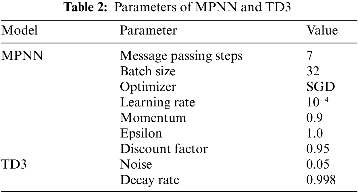
Table 2 provides the key parameters employed during the training of the MPNN-TD3 algorithm. The algorithm used SGD as the optimizer for MPNN, with a learning rate of
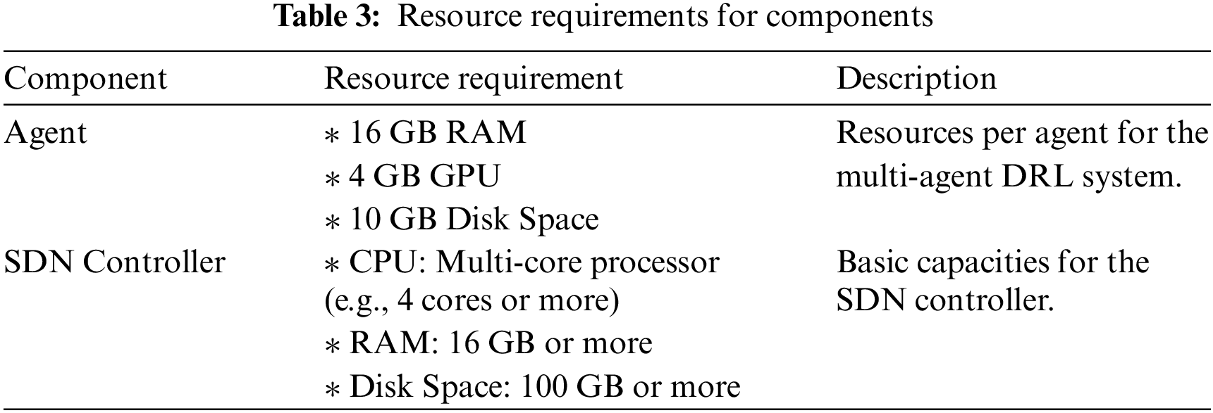
To orchestrate this multi-agent system, CoopAI-Route incorporates an SDN controller. The SDN controller is the central hub for managing and configuring network devices. It necessitates a multi-core processor (ideally four cores or more) to manage communication with numerous agents and network devices. Additionally, the SDN controller requires a minimum of 16 GB of RAM to run the SDN software and maintain routing tables. Finally, 100 GB or more of disk space is recommended to store network configurations and logs.
The experimentation was conducted on a server with an Intel Xeon E5-2650 processor, 128 GB of RAM, and four GTX 1080ti graphics processing unit cards. Additional considerations included scalability, appropriate Mininet configurations for the desired network parameters, and the development of automation scripts or frameworks to streamline the testing process.
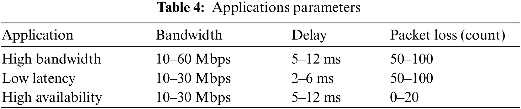
The number of SDN domains represented distinct network providers or administrative divisions in the initial network design phase. The simulations were run on a vast multi-domain setup to demonstrate the scalability of CoopAI-Route in multi-agent operations. The multi-domain SDN, as cited in [24], consisted of 158 intra-domain links, 44 inter-domain links, and 61 nodes. The starting and ending nodes for traffic flows were randomly selected from the 9 domains (Fig. 6). Traffic requests are likely generated based on the Table 4 range for bandwidth, delay, and packet loss (
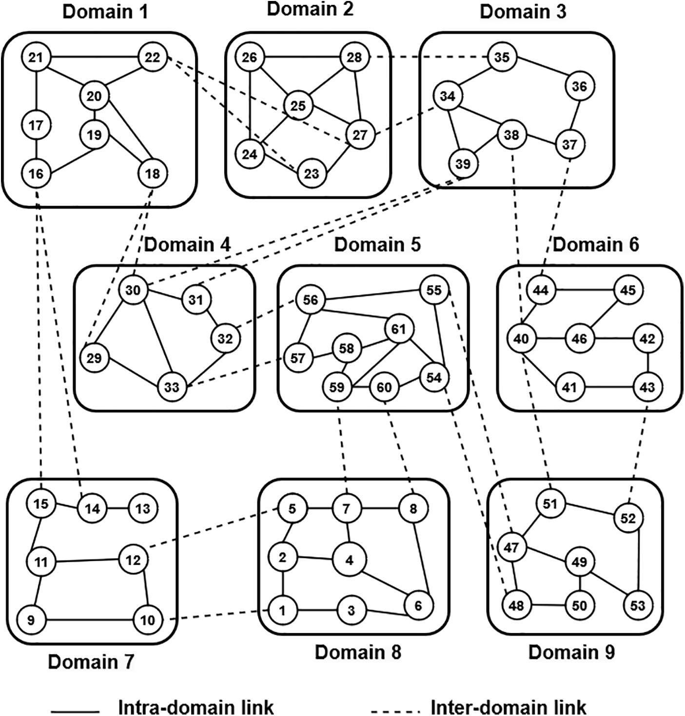
Figure 6: Multi-domain SDN network
Different traffic datasets simulating video streaming, web applications, and file transfer were generated using Iperf. We varied bandwidth (e.g., 1 Mbps to 1 Gbps), delay (e.g., 10 to 100 ms), and packet loss (e.g., 0% to 5%) to create a comprehensive range of network slice routing path requests. This approach allows CoopAIRoute to learn and adapt to diverse network conditions, addressing the high availability, ultra-low latency, and ultra-high bandwidth requirements of 5G applications. While our current testing focused on a simulated environment, we plan to evaluate CoopAIRoute’s performance in a pilot production deployment in the future.
The performance evaluation of multi-domain SDN with network slice enforcement involved assessing various aspects to ensure optimal functionality. Our evaluation addresses key metrics for a well-functioning network, aligning well with our priorities. It assesses throughput, ensuring efficient data transfer and E2E latency, which is critical for real-time applications. Scalability guarantees the network can grow as needed, while link failure handling and adaptability to evolving topologies ensure smooth operation even with changes in network structure or connection disruptions. This evaluation aimed to address intra and inter-domain paths, emphasizing the reduction of network slice traffic route rejection rates and enhancing QoS in a multi-domain environment.
1. Traffic Demand-Based Network Slice Rejection Rate: To gauge the system’s efficiency, we evaluated the rejection rate based on traffic demand for network slices. This criterion provided insights into how well the network accommodated varying traffic levels, highlighting areas for improvement and optimization.
2. Traffic Load-Based Network Slice Rejection Rate: Examining the rejection rate under different traffic loads was crucial for understanding system performance under varying network conditions. By considering the rejection rate of traffic load, we could optimize resource allocation and enhance the system’s ability to handle fluctuations in demand.
3. E2E delay for various network slice traffic route requests: E2E delay was a critical metric for assessing the responsiveness of the network. Evaluating this parameter for different network slice traffic route requests allowed us to identify potential bottlenecks, optimize routing algorithms, and improve communication efficiency.
4. Throughput: The overall throughput across the entire network slice, considering all domains and the data flow between them. This evaluation should reflect the ability of the network slice to deliver data efficiently from the source to the destination.
5. Packet loss: Packet loss in terms of multi-domain routing in network slicing are essential for ensuring the reliability and quality of service within the network slice. This criterion highlights the effectiveness of multi-domain routing mechanisms in minimizing packet loss during data transfer between disparate parts of the network slice.
6. Link Utilization: Efficient use of network links was fundamental to maximizing network performance. Evaluating link utilization helped identify underutilized or congested links, enabling proactive adjustments to improve overall network efficiency and reduce the rejection rate.
7. Scalability: Assessing the system’s scalability was essential for accommodating growing demands. By evaluating scalability, we could identify potential limitations and implement solutions to ensure the network could handle increased traffic and a growing number of network slice traffic route requests.
8. Dynamic Link Failure: Understanding how the system responded to dynamic link failures was crucial for ensuring network reliability. This evaluation criterion focused on the network’s ability to adapt to unforeseen circumstances, minimize downtime, and maintain a low rejection rate in the face of link failures.
A comparison with SAP [26], LB [26], and DeepRMSA [27] was made to assess the efficiency of CoopAI-Route. Fig. 1 provides a visual representation of the functional concept of CoopAI-Route, utilized by the benchmarks for cross-domain provisioning. In CoopAI-Route, the RMs always selected inter-domain links that consumed the least bandwidth to reach the next domain. DeepRMSA, on the other hand, used a DRL agent in each domain to make decisions on intra-domain provisioning techniques and selected inter-domain links with the lowest utilization for subsequent domains. With the action space in DeepRMSA predicated on intra-domain pathways and the utilization of their links, DRL agents in various domains could not communicate with one another or collaborate on inter-domain provisioning. The evaluation of QoS involved analyzing latency and packet loss for each slice to determine compliance with their respective requirements.
5.3 Training Performance of CoopAI-Route
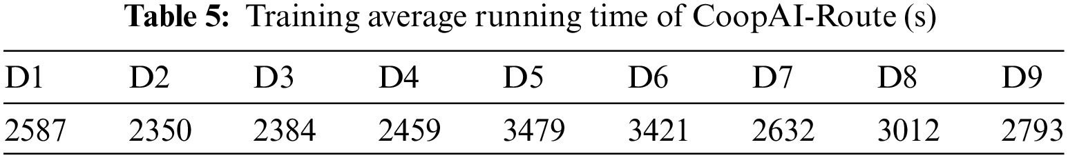
To start with, CoopAI-Route’s training procedures were examined so that every DRL agent could optimize their long-term profits. It is important to note that CoopAI-Route’s training could be done both online and offline. The DRL agents’ learnable parameters were initialized at random during offline training and then optimized to ensure the readiness of each RM’s DRL agent for online operation and training. As a result, completion of the offline training before deploying the DRL agents was needed for the multi-domain SDN. During the online training phase, CoopAI-Route employed its DRL agents to set up inter-domain paths, recording the provisioning results as additional training samples. The training samples were used to fine-tune the DRL agents’ parameters to ensure their functioning in the multi-domain SDN network. The amount of time each DRL agent needs for offline training is listed in Table 5. The offline training for all agents took less time than usual, except those responsible for Domains 5 and 6, situated in the middle of the nine-domain SDN and with a comparatively high number of nodes.
5.4 Traffic Demand-Based Network Slice Traffic Route Rejection Rate
The paper focused on reducing network slice traffic route request rejection rate as the primary indicator for comparing different inter-domain path provisioning strategies. This is because, in a multi-domain SDN, each rejected route request directly impacts the RM revenues. It also has a strong correlation with a variety of other measures.
Network slice application considerations include high availability, low latency, and high bandwidth. The bandwidth, delay, and packet loss requirements for each network slice were specified using

Figure 7: Network slice traffic route request rejection rate based on the number of route requests arrived

Figure 8: High availability slice traffic route request rejection rate based on the number of route requests arrived

Figure 9: Low latency slice traffic route request rejection rate based on the number of route requests arrived

Figure 10: High bandwidth slice traffic route request rejection rate based on the number of route requests arrived
5.5 Traffic Load-Based Network Slice Rejection Rate
The test conducted three network slice applications, and mixed application traffic ensured the consistency of addressing the network slice route request. In that experiment, 3000 network slice traffic route requests were considered for slice-specific applications and mixed traffic. Mixed network slice traffic route requests were further considered, distributed as 40% for high availability, 30% for low latency, and 30% for high bandwidth slices.
Simulations were conducted with varying traffic volumes: 10, 20, 30, 40, and 50 Mbps. The test initially involved sending constant traffic to the system with 10 Mbps of data through the links. Afterward, the network slice traffic route request was generated to evaluate the network slice traffic route request rejection rate. These experiments were done for 10, 20, 30, 40, and 50 Mbps.
Figs. 11–14 show the achievement of the lowest rejection rate across different traffic volumes by CoopAI-Route. Specifically, at a 10 Mbps traffic load, CoopAI-Route was observed to reduce the rejection rate by a maximum of 26% compared to SAP and an average of 24% compared to LB. Fig. 11 also demonstrates the performance of DeepRMSA as worse than CoopAI-Route, providing evidence of the beneficial nature of promoting cooperation among DRL agents.

Figure 11: Network slice traffic route request rejection rate based on the various traffic loads

Figure 12: Network slice traffic route request rejection rate based on the various traffic loads

Figure 13: Network slice traffic route request rejection rate based on the various traffic loads

Figure 14: Network slice traffic route request rejection rate based on the various traffic loads
Applications with high bandwidth requirements experienced a slightly higher rejection rate than others. This is because the system already has a high traffic volume, making it difficult to place new requests. Compared to all other state-of-the-art methods, CoopAI-Route has a low rejection rate. It is important to note that CoopAI-Route only shared limited intra-domain information among DRL agents. This strikes a good balance between path provisioning performance and domain privacy. Thus, considerations like topology and traffic load influenced the decision of which method to use for inter-domain service provisioning in each domain. Since the network’s state changed over time, doing so was complicated. Deterministic algorithms alone were unable to address this challenge. Using DRL, CoopAI-Route effectively addressed this complex problem while minimizing the rejection rate.
5.6 Effectiveness of Link Utilization
The performance of link utilization was directly proportional to a lower rejection rate in the network slice traffic QoS demand. In this study, 1000, 2000, 3000, 4000, and 5000 network slice traffic route requests were sent to different methods to analyze link bandwidth utilization. Minimal link usage represented the total traffic distribution throughout the network, explaining CoopAI-Route’s attempt to optimize the load-balancing aspect of the network. Improved load balancing led to lower maximum link utilization. Fig. 15 shows CoopAI-Route effectively reducing the maximum link utilization compared to the other three approaches. Employing the standard deviation of link utilization in CoopAI-Route contributed to achieving balanced link utilization throughout the network. The significant impact of CoopAI-Route was observed in the substantial reduction in maximum link utilization in a topology with numerous nodes and links.

Figure 15: Number of network slice traffic route request and their link Utilization
5.7 Performance on E2E Latency
The E2E delay was caused by both link features and link capacity. It could be calculated using the following equation, widely accepted in the field [28], which incorporated link capacity:
The performance of E2E latency is considered for both application slices and mixed slices. Each application slice routes traffic requests of various sizes (1000, 2000, 3000, 4000, and 5000) tested in this experiment. The mixed traffic comprises 40%, 30%, and 30% of high availability, low-latency, and high bandwidth slice application route requests, respectively. Figs. 16–19 show the latency results. The x-axis represents the number of route requests, and the y-axis represents the latency in milliseconds. Across all figures, SAP and LB exhibit the highest E2E latency compared to DeepRMSA and CoopAI-Route. While CoopAI-Route’s primary focus was not solely minimizing E2E delay, it still achieved good performance in this aspect. This is because CoopAI-Route considers various factors in its decision-making process. Experimental data on the multi-domain topology demonstrates CoopAI-Route’s outperformance over LB, SAP, and DeepRMSA in reducing E2E delay. This observation is evident from the results presented in Fig. 16. The reduced link load achieved by CoopAI-Route leads to a proportional decrease in E2E delay within the network architecture. For instance, compared to SAP, LB, and DeepRMSA, CoopAI-Route achieved an average reduction in E2E delay of 55.02%, 51.08%, and 46%, respectively. These findings were consistent for the training topology, which had the most nodes and edges.

Figure 16: Network slice traffic route rejection rate based on the E2E latency

Figure 17: Network slice traffic route rejection rate based on the E2E latency

Figure 18: Network slice traffic route rejection rate based on the E2E latency

Figure 19: Network slice traffic route rejection rate based on the E2E latency
5.8 Evaluation Focus on Throughput
The performance of throughput is considered for both application slices and mixed slices. Each application slice routes traffic requests of various sizes (1000, 2000, 3000, 4000, and 5000) tested in this experiment. The mixed traffic comprises 40%, 30%, and 30% of high availability, low-latency, and high bandwidth slice application route requests, respectively. Fig. 20 illustrates the superior throughput performance of CoopAI-Route compared to other routing systems. Throughput refers to the number of requests a system can handle per unit time. Here, we evaluate different routing systems under varying numbers of path requests. Higher throughput values indicate better performance in efficiently handling these requests. The results demonstrate that CoopAI-Route consistently outperforms or matches the throughput of other systems across all tested request levels. For example, with 1000 path requests, CoopAI-Route achieves a throughput of 603 Mbps, significantly exceeding DeepRMSA’s throughput of 502 Mbps. The advantage of CoopAI-Route becomes even more pronounced with increasing load. At 5000 path requests, the throughput of SAP is approximately 67.6% lower than CoopAI-Route’s. Similarly, LB lags behind by about 62.4%. While DeepRMSA performs better than SAP and LB, its throughput still falls behind CoopAI-Route by around 33.8%.
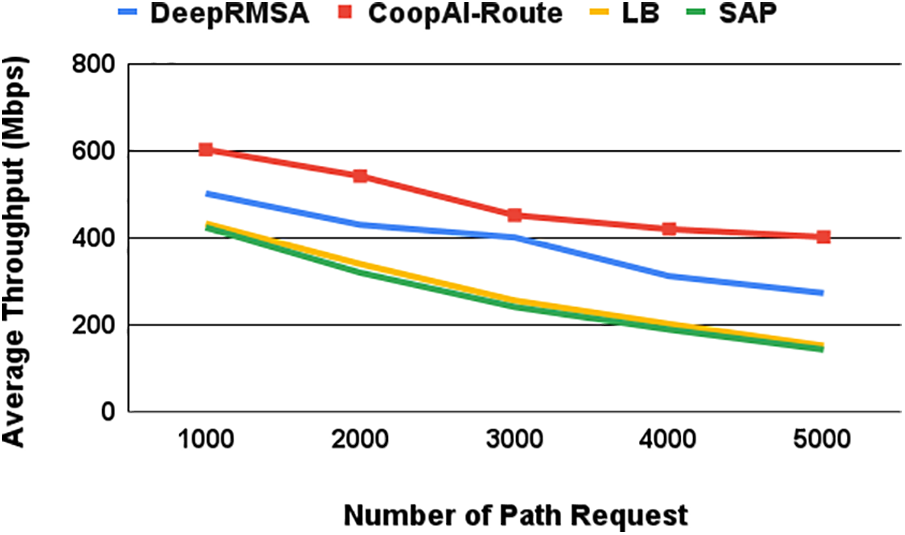
Figure 20: Average throughput based on the number of path requests
These results highlight a significant performance advantage of CoopAI-Route over other tested routing systems. This suggests that CoopAI-Route is likely more scalable and better optimized for handling high volumes of path requests. In other words, CoopAI-Route can efficiently manage routing tasks even under heavy loads, making it a promising solution for demanding routing scenarios.
5.9 Evaluation Focus on Packet Loss
The performance of packet loss is considered for both application slices and mixed slices. Each application slice routes traffic requests of various sizes (1000, 2000, 3000, 4000, and 5000) tested in this experiment. The mixed traffic comprises 40%, 30%, and 30% of high availability, low-latency, and high bandwidth slice application route requests, respectively. Fig. 21 illustrates packet loss performance across various routing systems: SAP, LB, DeepRMSA, and CoopAI-Route. The experiment evaluated these systems under increasing numbers of path requests, simulating network traffic loads. Packet loss signifies the percentage of data packets failing to reach their intended destination. As path requests rise (indicating higher network load), packet loss generally decreases for all routing systems. This suggests that under increased load, the systems might become more adept at delivering packets efficiently.
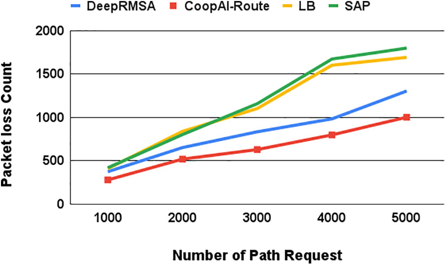
Figure 21: Packet loss based on the number of path requests
Notably, CoopAI-Route exhibits consistently lower packet loss compared to other systems across all traffic loads tested. For instance, with 1000 path requests, other state-of-the-art systems experience significantly higher packet loss: 37.5% for DeepRMSA, 41.0% for LB, and 42.0% for SAP. The advantage of CoopAI-Route becomes even more increased as path requests increase. By 5000 path requests, all other routing systems tested show considerably higher packet loss compared to CoopAI-Route. These findings indicate that CoopAI-Route offers superior reliability in packet delivery. It maintains lower packet loss percentages even under heavy network loads compared to traditional routing systems. This enhanced reliability is critical for guaranteeing data integrity and ensuring smooth communication within a network.
5.10 Evaluations on Scalability
Evaluated the scalability of CoopAI-Route in simulations with 10, 15, and 20 domains, each containing 10 nodes. Table 6 shows the performance results. By examining rejection rates more closely, can quantify the performance advantage of CoopAI-Route compared to other methods. The table shows the difference in the number of rejected path requests between CoopAI-Route and each of the other protocols, under both 2000 and 5000 traffic route request conditions.
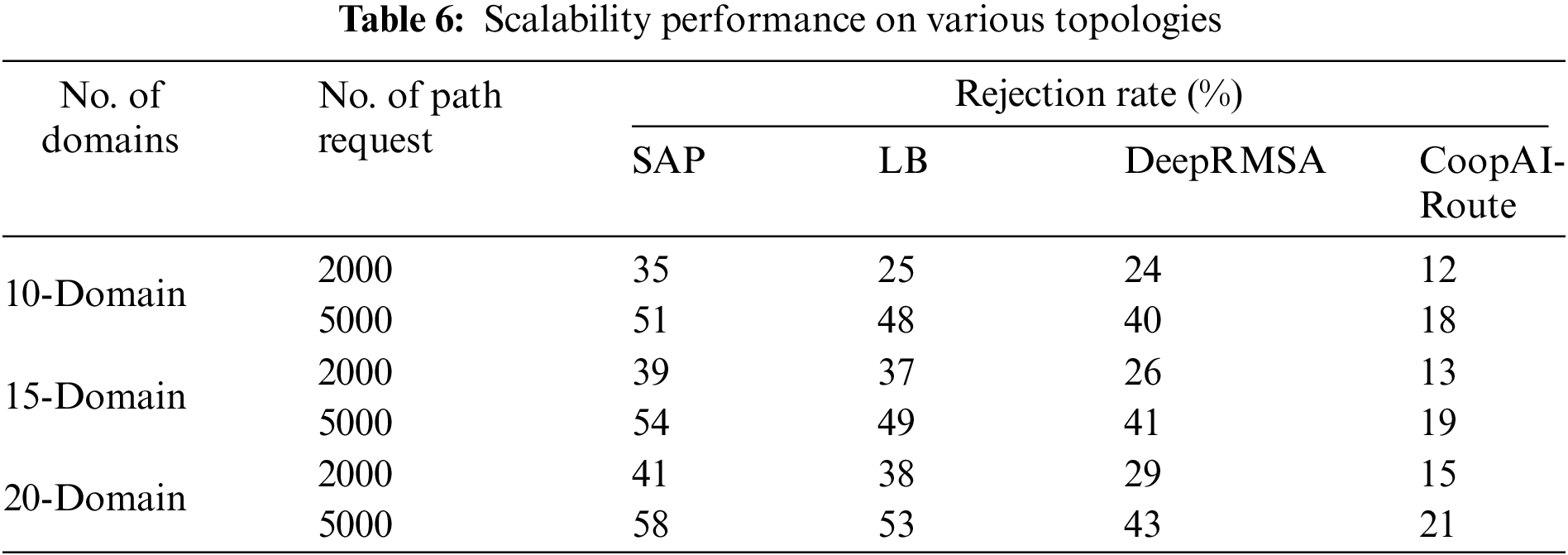
Under normal traffic with 2000 path requests, CoopAI-Route outperforms SAP by 23% to 26%, LB by 13% to 24%, and DeepRMSA by 12% to 14%. This advantage becomes even more pronounced under 5000 path requests. Here, CoopAI-Route surpasses SAP by 33% to 37%, LB by 30% to 32%, and DeepRMSA maintains a similar difference of 22% to 22%. CoopAI-Route consistently demonstrates a lower rejection rate compared to other state-of-the-art mechanisms, particularly under high-traffic route requests. This translates to a significant improvement in efficiently handling path requests within these network configurations.
CoopAI-Route appears to be a strong contender based on rejection rates. To demonstrate its adaptability and scalability, additional real-world topology simulations were conducted using a multi-domain SDN (shown in Fig. 22). Despite this topology comprising only three domains, each domain was significantly larger on average compared to the nine domains in Fig. 6. CoopAI-Route implemented cross-domain provisioning in this three-domain SDN with only minor tweaks. Fig. 23 shows the training rejection rate as the number of route requests increased (assuming a constant traffic load of 10 Mb/s).

Figure 22: 3-Domain real-world test topology (Geant2)

Figure 23: 3-Domain network slice traffic route request rejection rate based on the number of path requests
The results confirmed that CoopAI-Route outperformed the heuristics in terms of a lower rejection rate. Comparison between the results in Figs. 7 and 23 revealed that the training of CoopAI-Route in multi-domain SDNs remained consistent despite employing different topologies. This demonstrates the robustness and scalability of CoopAI-Route’s distributed online training system. Results for the rejection rate in the three-domain SDN provided in Fig. 23 followed the same pattern as that seen in Fig. 7. Table 7 shows the average time each algorithm took to return a path between domains.
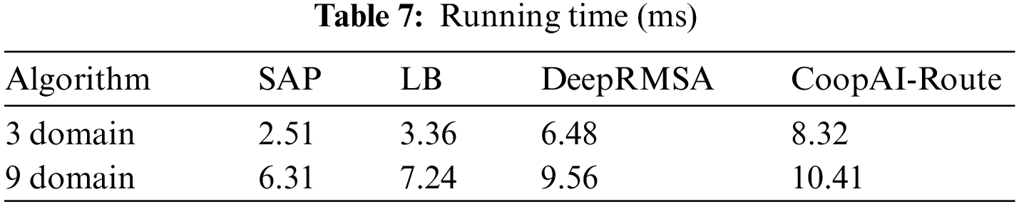
Since offline training is required before deploying any DRL model, the focus was on online operation and training time, disregarding the runtime of offline training. The findings in Table 7 indicate that CoopAI-Route processed each inter-domain request in milliseconds.
CoopAI-Route exhibited a slight increase in execution time as the number of domains increased. The execution time of deterministic heuristics (LB and SAP) often doubled when the number of SDN domains increased to nine. This indicates that CoopAI-Route is well-suited for dynamic provisioning, showcasing its scalability on large topologies.
One of the key challenges in large-scale routing systems is communication and synchronization overhead. Traditional systems often require all agents to communicate and coordinate with each other to determine the optimal route. This constant data exchange can significantly slow down the system, especially in complex networks with many agents. CoopAI-Route tackles this challenge by introducing the DGT algorithm. DGT acts as an intelligent filter, intelligently selecting specific domains (groups of agents) to participate in the routing process. This strategic selection significantly reduces the overall number of agents involved in communication. The communication within each domain primarily relies on DRL. DRL allows agents within a domain to collaborate and learn from each other, effectively finding the best route within their designated area. This focused collaboration further reduces communication overhead and potentially leads to faster route calculations.
However, CoopAI-Route with DGT does not compromise global efficiency. By cleverly coordinating the results from each domain, the system can still achieve an optimal routing solution for the entire network. This balance between reduced communication and maintaining global efficiency makes CoopAI-Route so scalable. Unlike traditional systems that struggle with communication overload as the network grows, CoopAI-Route with DGT can effectively handle complex routing tasks even in large and distributed networks. CoopAI-Route distinguished itself from competing models by demonstrating efficient execution times and minimal growth in execution time with an increase in the number of domains. These characteristics further highlight its suitability for dynamic provisioning. The results provided strong evidence of CoopAI-Route’s scalability on large topologies.
CoopAI-Route’s Scalability and Adaptation for Evolving Networks
Table 6 summarizes performance metrics for different network sizes (number of domains). The discussion of DGT underlines CoopAI-Route’s potential to handle large-scale networks. Traditional routing systems can become overloaded with communication as the network expands. CoopAI-Route’s DGT algorithm tackles this issue by strategically selecting specific groups of agents (domains) to participate in routing. This significantly reduces the number of communicating agents, making CoopAI-Route well-suited for complex routing tasks in large networks. DRL is employed within each domain. Agents within a domain collaborate and learn from each other to discover optimal routes within their designated area. This focused collaboration further minimizes communication overhead and potentially leads to faster route calculations, contributing to efficient routing in large-scale networks.
Adaptation Mechanisms for Evolving Topologies
CoopAI-Route appears to utilize a three-pronged approach for adaptation:
• GNN: Continuously analyzes the network graph (including devices and connections) to detect changes in topology, such as new nodes or fluctuations in bandwidth.
• SDN-Based Network Updates: SDN serves as the bridge between CoopAI-Route and the physical network. The SDN controller periodically retrieves information from network switches, feeding real-time data into CoopAI-Route to update the GNN’s understanding of the network state.
• DRL for Rapid Change Identification: Analyzes network updates received from the SDN controller (including link status and congestion levels) to identify significant deviations from the baseline network state learned by the GNN, signaling rapid network changes.
This approach suggests potential advantages for CoopAI-Route’s resilience.
5.11 Performance on Dynamic Link Failure
To evaluate CoopAI-Route’s flexibility to changes in the underlying network architecture scenarios including frequent network link failures were simulated. Real-world networks experience topological changes over time, such as link failures [28]. Up to ten link failures were explored across a variety of circumstances. The objective of CoopAI-Route was to find alternative routing configurations that improve throughput and reduce the load on the remaining links. Experiments were conducted where n (from 1 to 10) links in the Geant2 topology were removed randomly. The rejection rate (bandwidth allocation) of the CoopAI-Route agent was compared with that of the competing techniques. Average connection failures (x-axis) and rejection rate (y-axis) are shown in Fig. 24. CoopAI-Route maintained performance above the baseline even with simultaneous breaks in two connections. This demonstrated the adaptability of the proposed CoopAI-Route architecture, as it could effectively handle multiple link failures and still deliver satisfactory performance.

Figure 24: Network slice traffic route request rejection rate based on the dynamic link failure
This GNN likely continuously analyzes the network graph, which includes information about devices (nodes) and their connections (relationships). By constantly processing this data, the GNN could potentially detect changes in the network state, such as:
• Fluctuations in link weight (indicating bandwidth changes)
• Addition or removal of nodes
• Changes in link status (up/down)
SDN serves as the communication bridge between CoopAI-Route and the physical network. The SDN controller periodically retrieves information from network switches, including link status, available bandwidth, and congestion levels. This real-time data is fed into CoopAI-Route, allowing it to update its understanding of the current network state.
The study proposes a CoopAI-Route system for managing network slices and evaluates its effectiveness through multiple benchmarks. The system prioritizes efficient traffic handling by considering traffic demand and load to minimize rejection rates. It also measures responsiveness through E2E delay analysis, allowing for bottleneck identification and routing optimization within slices. Link utilization is evaluated to avoid congestion and underutilized resources and ensure efficient resource allocation. Furthermore, the system’s scalability is assessed for future traffic growth and network slice requests. Finally, the system’s response to dynamic link failures is analyzed to minimize downtime and maintain low rejection rates even during unexpected events. Overall, this evaluation approach demonstrates the system’s effectiveness in managing network slices and optimizing their performance under various conditions.
CoopAI-Route with MPNN-TD3 addresses the challenge of performing well in unforeseen scenarios through its design elements. The DGT algorithm allows CoopAI-Route to conquer diverse network topologies by dividing the network into manageable domains. Within each domain, agents collaborate and learn routing strategies specific to their local traffic patterns and network graphs. Adapting to local conditions empowers CoopAI-Route to function effectively across different network configurations.
Furthermore, MPNN-TD3 forms the core of CoopAI-Route’s DRL prowess. These models are adept at handling graph-structured data, perfectly aligning with transportation networks where locations (nodes) connect via routes (edges). Regardless of the underlying network topology, MPNNs can effectively learn the intricate patterns and relationships within the network. To ensure optimization for the global good, CoopAI-Route incorporates TD3. TD3 focuses on maximizing a global reward function, which translates to finding the optimal route for the entire network in the routing context. This overarching objective ensures that even though agents learn within their designated domains, they ultimately work towards a solution that benefits the entire system, irrespective of the specific traffic patterns present.
To convincingly demonstrate CoopAI-Route’s ability to handle diverse network environments, we should showcase its performance on various network topologies and traffic patterns. Running CoopAI-Route on simulated networks with different topologies and traffic patterns would provide valuable insights. Real-world deployment could improve the system’s ability to generalize and handle traffic patterns, such as peak and regular hours traffic.
The most difficult part of the work is that multi-agent DRL offers a promising approach for managing complex multi-domain SDN networks, but it faces hurdles. Coordinating and communicating across different domains remains intricate, and the reliance on message passing creates vulnerability to network disruptions. However, these agents’ ability to learn and adapt allows them to discover optimal paths that deliver the necessary QoS for various network slice applications. Combining SDN with DRL achieves domain-level privacy, a significant improvement over traditional systems. However, security in multi-domain communication remains an area for further exploration. Moving forward, the focus should be on enhancing communication security through measures like encryption, authentication, and redundancy. This will ensure reliable information exchange and ultimately lead to a more robust and efficient network management system. This remains a key focus for future research.
This research article introduces CoopAI-Route, a framework for scalable network management across many SDN domains that utilize cooperative DRL agents to provide network slice-based inter- and intra-domain path services. CoopAI-Route employs DRL agents at the domain level to maximize the QoS provided between different domains. PCE is implemented to establish the best path to traverse domains for every given network slice traffic route request. The decentralized nature of the DRL agents enables them to make independent decisions while sharing limited information. The MPNN-TD3 approach has been developed to enhance scalability and generalizability.
CoopAI-Route leverages the capabilities of the GNN to analyze the network environment in a multi-domain SDN and select the optimal path to minimize the network slice traffic route request rejection rate. Extensive simulation scenarios demonstrated that CoopAI-Route outperforms existing algorithms for inter-domain provisioning. Additionally, the distributed training approach implemented in this work has proved successful.
One of the key strengths of CoopAI-Route is its generalization capability. Modeling networks as graphs and employing GNN keeps the system involved in analyzing network data and enables the interaction of distributed agents with their neighbors based on the underlying graph structure. This assists CoopAI-Route in adapting to and performing well in diverse network environments, making it a versatile solution for inter-domain and intra-domain path services.
Acknowledgement: The authors wish to express their appreciation to the reviewers for their helpful suggestions, which greatly improved the presentation of this paper.
Funding Statement: The authors received no specific funding for this study.
Author Contributions: Study conception and design: Meignanamoorthi Dhandapni; analysis and interpretation of results: Meignanamoorthi Dhandapni; draft manuscript preparation: Meignanamoorthi Dhandapni, V. Vetriselvi, R. Aishwarya.
Availability of Data and Materials: The data utilized in this study were generated using a traffic generator to simulate diverse network conditions and behaviors.
Conflicts of Interest: The authors declare that they have no conflicts of interest to report regarding the present study.
References
1. Jain P, Gupta A, Kumar N. A vision towards integrated 6G communication networks: promising technologies, architecture, and use-cases. Phys Commun. 2022;55:101917. doi:10.1016/j.phycom.2022.101917. [Google Scholar] [CrossRef]
2. Xie Y, Kong Y, Huang L, Wang S, Xu S, Wang X, et al. Resource allocation for network slicing in dynamic multi-tenant networks: a deep reinforcement learning approach. Comput Commun. 2022;195:476–87. doi:10.1016/j.comcom.2022.09.015. [Google Scholar] [CrossRef]
3. Guo Y, Luo H, Wang Z, Yin X, Wu J. Routing optimization with path cardinality constraints in a hybrid SDN. Comput Commun. 2021;165:112–21. doi:10.1016/j.comcom.2020.11.004. [Google Scholar] [CrossRef]
4. Podili P, Kataoka K. TRAQR: trust aware end-to-end QoS routing in multi-domain SDN using blockchain. J Netw Comput Appl. 2021;5:182. [Google Scholar]
5. Ventre PL, Salsano S, Polverini M, Cianfrani A, Abdelsalam A, Filsfils C, et al. Segment routing: a comprehensive survey of research activities, standardization efforts, and implementation results. IEEE Commun Surv Tutor. 2021;23:182–221. doi:10.1109/COMST.9739. [Google Scholar] [CrossRef]
6. Wu JW, Qiao XQ, Chen JL. PDMR: priority-based dynamic multi-path routing algorithm for a software defined network. IET Commun. 2019;13:179–85. doi:10.1049/cmu2.v13.2. [Google Scholar] [CrossRef]
7. Elbasheer MO, Aldegheishem A, Alrajeh N, Lloret J. Video streaming adaptive QoS routing with resource reservation (VQoSRR) model for SDN networks. Electronics. 2022;4:11. [Google Scholar]
8. Balakiruthiga B, Deepalakshmi P, Mohanty SN, Gupta D, Pavan Kumar PKS. Segment routing based energy aware routing for software defined data center. Cogn Syst Res. 2020;64:146–63. doi:10.1016/j.cogsys.2020.08.009. [Google Scholar] [CrossRef]
9. Dai B, Cao Y, Wu Z, Xu Y. IQoR-LSE: an intelligent QoS on-demand routing algorithm with link state estimation. IEEE Syst J. 2022;16:5821–30. doi:10.1109/JSYST.2022.3149990. [Google Scholar] [CrossRef]
10. Kim G, Kim Y, Lim H. Deep reinforcement learning-based routing on software-defined networks. IEEE Access. 2022;10:18121–33. doi:10.1109/ACCESS.2022.3151081. [Google Scholar] [CrossRef]
11. Sun P, Guo Z, Li J, Xu Y, Lan J, Hu Y. Enabling scalable routing in software-defined networks with deep reinforcement learning on critical nodes. IEEE/ACM Trans Netw. 2022;30:629–40. doi:10.1109/TNET.2021.3126933. [Google Scholar] [CrossRef]
12. Xia D, Wan J, Xu P, Tan J. Deep reinforcement learning-based QoS optimization for software-defined factory heterogeneous networks. IEEE Trans Netw Serv Manag. 2022;19:4058–68. doi:10.1109/TNSM.2022.3208342. [Google Scholar] [CrossRef]
13. Sun P, Guo Z, Wang G, Lan J, Hu Y. MARVEL: enabling controller load balancing in software-defined networks with multi-agent reinforcement learning. Comput Netw. 2020;8:177. [Google Scholar]
14. Wang YC, Chang EJ. Cooperative flow management in multi-domain SDN-based networks with multiple controllers. In: 2020 IEEE 17th International Conference on Smart Communities: ImprovingQuality of Life Using ICT, IoT and AI (HONET); 2020; Charlotte, NC, USA. p. 82–6. [Google Scholar]
15. Joshi KD, Katako K. PRIME-Q: privacy aware end-to-end QoS framework in multi-domain SDN. In: 5th IEEE Conference on Network Softwarization; 2019 Jun 24–28; France; IEEE. p. 169–77. [Google Scholar]
16. Moufakir T, Zhani MF, Gherbi A, Bouachir O. Collaborative multi-domain routing in SDN environments. J Netw Syst Manag. 2022;30:23. doi:10.1007/s10922-021-09638-0. [Google Scholar] [CrossRef]
17. Oroojlooy A, Hajinezhad D. A review of cooperative multi-agent deep reinforcement learning. Appl Intell. 2022;53(11):13677–13722. [Google Scholar]
18. Li Z, Zhou X, Gao J, Qin Y. SDN controller load balancing based on reinforcement learning. In:2018 IEEE 9th International Conference on Software Engineering and Service Science (ICSESS); 2018; Beijing, China.p. 1120–6. [Google Scholar]
19. Casas-Velasco DM, Rendon OMC, Fonseca NLSD. DRSIR: a deep reinforcement learning approach for routing in software-defined networking. IEEE Trans Netw Serv Manag. 2022;19:4807–20. doi:10.1109/TNSM.2021.3132491. [Google Scholar] [CrossRef]
20. Wang H, Xu H, Huang L, Wang J, Yang X. Load-balancing routing in software defined networks with multiple controllers. Comput Netw. 2018;141:82–91. doi:10.1016/j.comnet.2018.05.012. [Google Scholar] [CrossRef]
21. Godfrey D, Jang J, Kim KI. Weight adjustment scheme based on hop count in Q-routing for software defined networks-enabled wireless sensor networks. J Inf Commun Converg Eng. 2022;20:22–30. [Google Scholar]
22. Yuan T, da Rocha Neto W, Rothenberg CE, Obraczka K, Barakat C, Turletti T. Dynamic controller assignment in software defined internet of vehicles through multi-agent deep reinforcement learning. IEEE Trans Netw Serv Manag. 2021;18:585–96. doi:10.1109/TNSM.4275028. [Google Scholar] [CrossRef]
23. Du W, Ding S. A survey on multi-agent deep reinforcement learning: from the perspective of challenges and applications. Artif Intell Rev. 2021;54:3215–38. doi:10.1007/s10462-020-09938-y. [Google Scholar] [CrossRef]
24. Li B, Zhang R, Tian X, Zhu Z. Multi-agent and cooperative deep reinforcement learning for scalable network automation in multi-domain SD-EONs. IEEE Trans Netw Serv Manag. 2021;18:4801–13. doi:10.1109/TNSM.2021.3102621. [Google Scholar] [CrossRef]
25. Joshi T, Makker S, Kodamana H, Kandath H. Twin actor twin delayed deep deterministic policy gradient (TATD3) learning for batch process control. Comput Chem Eng. 2021;155:107527. [Google Scholar]
26. Chatterjee BC, Sarma N, Oki E. Routing and spectrum allocation in elastic optical networks: a tutorial. IEEE Commun Surv Tutor. 2015;17(3):1776–1800. doi:10.1109/COMST.2015.2431731. [Google Scholar] [CrossRef]
27. Chen X, Li B, Proietti R, Lu H, Zhu Z, Yoo SJB. DeepRMSA: a deep reinforcement learning framework for routing, modulation and spectrum assignment in elastic optical networks. J Lightwave Technol. 2019;37(16):4155–63. doi:10.1109/JLT.50. [Google Scholar] [CrossRef]
28. He Q, Wang Y, Wang X, Xu W, Li F, Yang K, et al. Routing optimization with deep reinforcement learning in knowledge defined networking. IEEE Trans Mob Comput. 2024;23(2):1444–55. [Google Scholar]
Cite This Article
 Copyright © 2024 The Author(s). Published by Tech Science Press.
This work is licensed under a Creative Commons Attribution 4.0 International License , which permits unrestricted use, distribution, and reproduction in any medium, provided the original work is properly cited.
 Downloads
 Citation Tools