 Open Access
ARTICLE
Film Flow of Nano-Micropolar Fluid with Dissipation Effect
1 Department of Basic Sciences & Humanities, Faculty of Engineering & Technology, Bahauddin Zakariya University, Multan, Pakistan
2 Department of Mathematics, Hacettepe University, Ankara, Türkiye
3 Department of Medical Research, China Medical University Hospital, China Medical University, Taichung, Taiwan
* Corresponding Authors: Mustafa Turkyilmazoglu. Email: ,
Computer Modeling in Engineering & Sciences 2024, 140(3), 2487-2512. https://doi.org/10.32604/cmes.2024.050525
Received 08 February 2024; Accepted 29 April 2024; Issue published 08 July 2024
Abstract
The physical problem of the thin film flow of a micropolar fluid over a dynamic and inclined substrate under the influence of gravitational and thermal forces in the presence of nanoparticles is formulated. Five different types of nanoparticle samples are accounted for in this current study, namely gold Au, silver Ag, molybdenum disulfide MoS2, aluminum oxide Al2O3, and silicon dioxide SiO2. Blood, a micropolar fluid, serves as the common base fluid. An exact closed-form solution for this problem is derived for the first time in the literature. The results are particularly validated against those for the Newtonian fluid and show excellent agreement. It was found that increasing values of the spin boundary condition and micropolarity lead to a reduction in both the thermal and momentum boundary layers. A quantitative decay in the Nusselt number for a micropolar fluid, as compared to a Newtonian one for all the tested nanoparticles, is anticipated. Gold and silver nanoparticles (i) intensify in the flow parameter as the concentration of nanoparticles increases (ii) yield a higher thermal transfer rate, whereas molybdenum disulfide, aluminum oxide, and silicon dioxide exhibit a converse attitude for both Newtonian and micropolar fluids. The reduction in film thickness for fluid comprising gold particles, as compared to the rest of the nanoparticles, is remarkable.Keywords
Nomenclature
| Dimensional Quantities | |
| Thermal Capacity | |
| Acceleration due to gravity | |
| Thickness of the film | |
| Gyration parameter | |
| Thermal conductivity ( | |
| Hydrodynamic pressure | |
| Axial component of spin vector | |
| Temperature | |
| Horizontal component of velocity of fluid | |
| Vertical component of velocity of fluid | |
| Abscissa | |
| Ordinate | |
| Viscosity parameter | |
| Nu | Nusselt number |
| Hydrodynamic pressure | |
| Discharge of fluid | |
| Reynolds number | |
| Axial component of spin vector | |
| Horizontal component of velocity of fluid | |
| Vertical component of velocity of fluid | |
| Abscissa | |
| Ordinate | |
| Greek Symbols | |
| Dimensionless flow parameter | |
| Dimensionless spin boundary parameter | |
| Dimensionless thermal parameter | |
| Dimensionless thermal parameter coefficient | |
| Dimensionless viscous dissipation parameter | |
| Vorticity Viscosity coefficient | |
| Dimensionless Volume fraction | |
| Spin gradient coefficient | |
| Viscosity coefficient | |
| Dimensionless temperature | |
| Angle of inclination of substrate | |
| Density | |
| Subscripts | |
| f | Fluid |
| s | Nanoparticles |
| nf | Nanofluid |
1.1 Thin Film Flow and Its Significance
Modern Touch of a Classical Flow Problem: Thin films of liquid are pervasive and ubiquitous across both the natural and human-made worlds. Thin film flow describes the spreading of a liquid over a solid substrate (static or dynamic) with a free surface, typically air or gas, at the interface. The flow is primarily driven by external forces, such as a translating or rotating substrate, surface tension, or gravitational force [1,2]. To further explore this, consider examples from nature and technology, including rainwater dribbling down a windowpane, blood coursing through tiny blood vessels, tears trickling down a cheek, suspensions oozing over substrates, and lubricant oil coating rotating ball bearings or other spinning objects [3–6]. Studying thin film flow has wide-ranging applications, aiding understanding of phenomena such as spin-coating, gravure printing, absorption columns, mudslides, dry processes, cooling of microelectronics devices, production of glass/wire, wettability, flow over roads/roofs, solar cells, film evaporation, food industry processes, and heat exchangers [7–11].
One application of thin film flow studies is the analysis of complex liquid flows over intricate substrates. For example, it can be utilized to model the surface-tension-driven flow of incompressible fluids, such as the lining of the lungs [12,13]. The complexity of these flows arises from two main factors:
• Substrate geometry: This can include flexible substrates like leaves [5] or the intricate lining of the lungs [13], as well as other examples like magma streams or tears on a face [14,15].
• Liquid properties: Beyond simple Newtonian fluids like pure water, the flow can involve liquids containing mud, non-Newtonian fluids, or even fluids with nanoparticles [16–20]. This study focuses specifically on micropolar fluids, which have complex molecular structures and include examples like blood, liquid crystals, and colloidal suspensions [21,22]. A deeper exploration of the fascinating properties of micropolar fluids will follow.
Currently, many literature sources exist on both theoretical and experimental studies of thin film flow for Newtonian and non-Newtonian fluids.
1.2 Literature Survey for Newtonian Fluid
The story of thin film flow began in 1916 with the work of Nusselt [23], who presented mathematical equations describing its dynamics. He derived the governing equation for thermal transfer coefficients in condensate thin films, assuming they primarily resist heat transfer. Subsequently, a significant contribution was made in 1974 by Tamir et al. [24], who extended Nusselt’s work by accounting for a constant surface resistance.
While a full historical account is beyond the scope of this discussion due to its substantial length, several noteworthy contributions have explored various aspects of thin film flow:
• Kondic et al. [25] examined thin film liquid on an inclined plane, concluding that the inclination angle significantly alters the wetting behavior.
• O’Brien et al. [26] built upon this work by detailing the implementation of the thin film lubrication approximation and presenting practical examples.
• Wang et al. [27] investigated the influence of channel shape on condensation in thin films within horizontal microchannels.
• Al-Jarrah et al. [28] described the process of film thickness development in microchannels.
• Gatapova et al. [29] analyzed the thermal effects of thin liquid film flow in a channel heated from below.
• Lin et al. [30] reported the dominant role of convective thermal transfer at high Reynolds numbers.
Applications and Experimental Verification: The applications of thin film flow extend beyond theoretical studies. For instance, Mazloomi et al. [31] utilized the lattice-Boltzmann method to investigate thin film flow with thermal sources for surface coating, while Slade [32] explored rivulet formation in thin liquid films. Experimental validation also plays a crucial role in understanding thin film flow. Several studies have focused on this aspect, including:
• Ju et al. [33] performed experiments to probe the droplet impinging on thin film flows and highlighted the characteristics of droplet evolution.
• Charogiannis et al. [34] conducted experiments on thin film flows over inclined glass planes driven by gravity, studying the relationship between the Nusselt number and Reynolds number.
• Wang et al. [35] investigated the thermal influence on thin films under a thermal source environment.
• Budakli [36] experimentally examined thin film flow generated from turbulent gas flow on heated inclined channel walls or under gravitational force.
• Markides et al. [37] conducted experiments to understand the effects of conjugate thermal transfer in thin film flow over electrically heated inclined substrates.
Micropolar Fluids with Nanoparticles: It is well known that nanoparticles in liquids can enhance thermal transfer rates and facilitate other valuable industrial phenomena, such as the instant cooling of electronic chips or rapid water heating in geysers and heat exchangers. Notably, reference [10] was the first to theoretically analyze the hydrodynamic and thermal effects of thin film flow in water containing seven different nanoparticles, even developing a closed-form solution for fluid velocity and temperature.
Contribution and Scope: Inspired by the work in [10], this study extends its analysis to explore other fluid types, such as micropolar fluids, which are relevant to blood, colloidal suspensions, and epoxies. It derives a closed-form solution for the thin film flow of a micropolar fluid containing five different nanoparticles over a thermally heated inclined plane.
1.3 Literature Survey for Non-Newtonian Fluid
In various industries, fluids such as tomato ketchup, honey, blood, colloidal suspensions, and mercury, along with other industrial fluids, do not behave ideally like water. These liquids are categorized as non-Newtonian fluids and require distinct models and constitutive equations to describe their flow behavior. The study of the thin film flow of such non-Newtonian fluids has yielded valuable insights [38–42]. To further explore it, let us examine some recent contributions from 2021 to 2023.
Recent Highlights (2021–2023):
• 2021:
○ Reference [43]: This study compared two methods, homotopy perturbation Elzaki transform and Elzaki decomposition, for analyzing the thin film flow of a third-grade fluid down an inclined plane, favoring the former for its efficacy.
○ Reference [44]: Research on Oldroyd-B ferrofluid containing nanoparticles (Cobalt Ferrite) employed the Runge-Kutta method for a numerical solution.
2022:
○ Reference [45]: Thin film flow of a Williamson fluid was numerically investigated using a homotopy-based scheme with Fractional Calculus, considering bio-convection and microorganism diffusivity.
○ Reference [46]: This study explored the thin film flow of a Casson nanofluid.
○ Reference [47]: This study analyzed viscoplastic Bingham fluid’s thin film flow behavior.
○ Reference [48]: Johnson-Segalmann fluid was the focus of this study on thin film flow.
2023:
○ Reference [49]: A third-grade fluid’s thin film flow characteristics were investigated.
○ Reference [50]: Johnson-Segalmann fluid was tackled in this study on thin film flow.
○ Reference [51]: Second-grade fluid’s thin film flow behavior was analyzed.
○ Reference [52]: Maxwell nanofluid’s thin film flow was explored.
○ Reference [53]: This study focused on Casson nanofluid, further advancing the understanding of thin film flow behavior.
Looking Forward: These examples highlight the active research landscape in non-Newtonian thin film flows. As this field continues to evolve, it offers immense potential for advancements in diverse areas such as bioengineering, microfluidics, and coating technologies.
1.4 Current Study and Micropolar Fluid
As discussed earlier, this study focuses on exploring the hydro- and thermo-dynamical effects of thin film flow in micropolar fluids containing nanoparticles. These fluids hold significant techno-scientific value and exist not only in the laboratory but also in the natural world. Blood, which represents the micropolar nature with its cellular and platelet components, is noted in [54,55]. Colloidal suspensions and liquid crystals, characterized by the presence of colloids, are also part of this category [56]. Rigid-rod epoxies, with their rod-like molecular structure and polymeric suspensions, further expand the diverse scope of micropolar fluids [22,57].
Micropolar fluids are distinguished from Newtonian and non-Newtonian fluids through their ability to sustain body couple and couple stress in addition to conventional body force and Cauchy stress. The Cauchy stress tensor in a micropolar fluid arises from the microscopic, needle-like particles it contains. While Newtonian fluids require only three degrees of freedom for analysis, micropolar fluids necessitate six, reflecting their more complex internal structure.
The literature on the thin film flow of micropolar fluids remains surprisingly sparse. A notable study from Yusuf et al. in 2021 [58] investigated this phenomenon over a static inclined porous substrate, primarily focusing on entropy analysis and employing numerical tools based on the differential transformation method. While this study is noteworthy, it leaves several intriguing questions unanswered, thus hindering a comprehensive understanding of micropolar fluid behavior in real-world situations.
Unanswered Questions and the Research Focus: These unaddressed questions become the driving force for the present research. For instance, how will the fluid respond to a heater within or near the substrate? What happens when the substrate becomes dynamic, moving at a uniform or non-uniform speed? What impact do different nanoparticles, incorporated as additive colloids, have on the flow dynamics? These and many more questions will guide this research, promising valuable insights into the world of micropolar fluids.
The Power of Nanoparticles: Nanoparticles play a vital role in shaping the landscape of modern technology [59–62]. Gold (Au) and silver (Ag) nanoparticles are extensively used in separation science, facilitating efficient separation processes [63–65]. Solutions of gold nanoparticles even reduce thermal resistance by 13% compared to pure water. These nanoparticles also hold vast potential in cancer treatment, where their heat-generating capability aids in photodynamic therapy.
Molybdenum disulfide
Aluminum oxide (
The Current Study: This study explores the thin film flow of a micropolar fluid (base fluid) containing five distinct types of nanoparticles. This flow occurs over an inclined substrate moving with a uniform speed (U) under the influence of gravity. Section 2 meticulously formulates the governing equations for this scenario. Section 3 then tackles the derivation of a closed-form exact solution for the corresponding boundary value problem. Section 4 shows the obtained results and provides insightful commentary on their implications. Finally, Section 5 wraps up the study by summarizing the essential findings and their significance.
2 Mathematical Formulation and Analysis of the Physical Problem
The governing equations for a steady flow of an incompressible, two-dimensional nano-micropolar fluid model [10,22,56] in the presence of viscous dissipation and in the absence of Joule heating and electromagnetic influences can be written as follows:
where
where
The above equations can be written in dimensionless form as follows:
This study considers the nano-micropolar liquid flowing over an inclined substrate with an angle of inclination, as shown in Fig. 1.
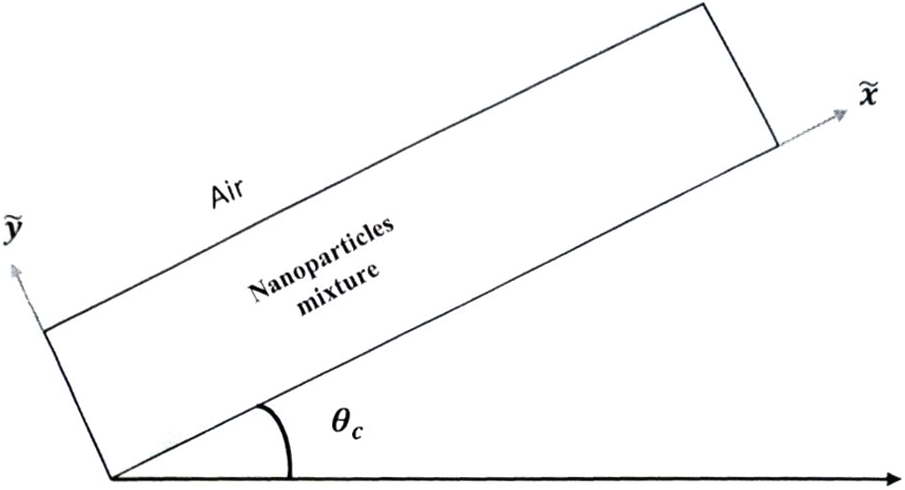
Figure 1: Flow configuration
The flow is generated by a pulling roller that is sliding along the x-axis with a constant fluid speed
Based on the aforementioned assumptions, Eqs. (8)–(11) deform, ensuring that Eq. (7) is satisfied as follows:
Furthermore, the boundary conditions can be written as follows:
3 Analytical Solution of the Problem
The aforementioned BVP in Eqs. (13)–(17) contains linear coupled ODE. Hence, it can be integrated exactly using standard methods. The solution for the fluid speed
In this scenario, the expression for thermal flux is as follows:
where
If
This section is devoted to presenting some dominant results both in tabular and pictorial forms and commenting on them. The results are based on the exact closed-form solution, Eqs. (19)–(21), of the physical problem under consideration.
In order to validate the calculations herein, Fig. 2b is set for fluid speed if
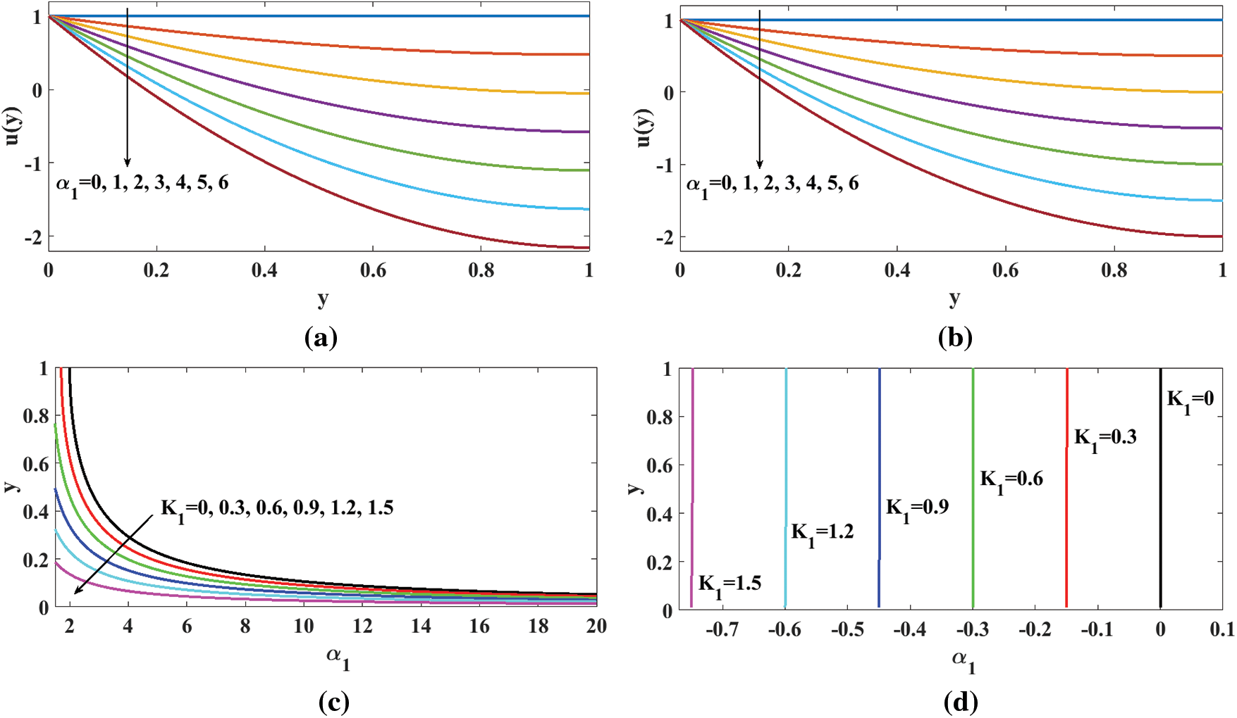
Figure 2: Fluid-speed profiles for: (a) micropolar fluid; (b) Newtonian fluid for different values of
As the flow is generated by moving upward the inclined substrate over it, the fluid is flowing, and the probability of reverse flow downward naturally is dominant. This fact is reflected in Fig. 2a as a negation of speed substrate-rider fluid. This reversal of fluid dominates with the rise in the flow parameter
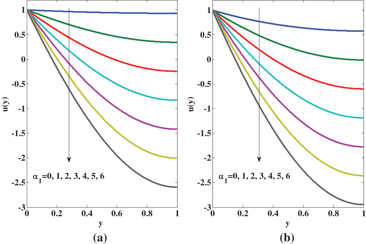
Figure 3: The effect of spin boundary condition on the fluid speed for micropolar fluid for different values of

where
(i) For the Newtonian fluid
It coincides with [10], as attempted for the Newtonian fluid. Further if angle of inclination is zero that implies
where
(ii) The fluid speed
(iii) The fluid speed
Since there are no aciculate particles that collide in the Newtonian fluid
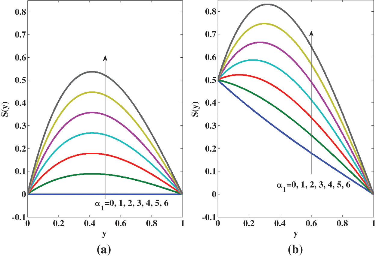
Figure 4: Variation of spin or microrotation of aciculate particles for micropolar fluid for different values of
Fig. 5 indicates that the spin rises with the micropolarity parameter
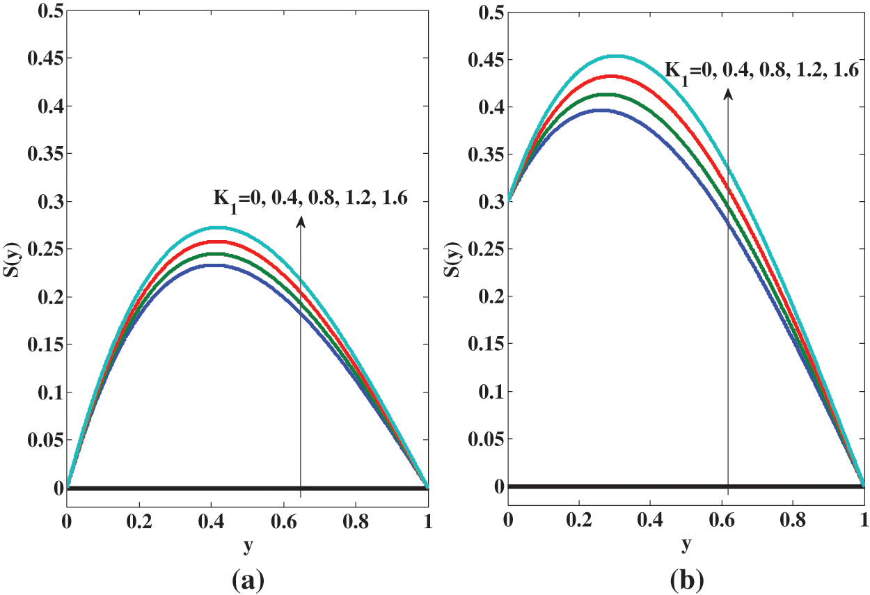
Figure 5: Variation of spin for micropolar fluid for different values of
According to Eq. (21), the temperature
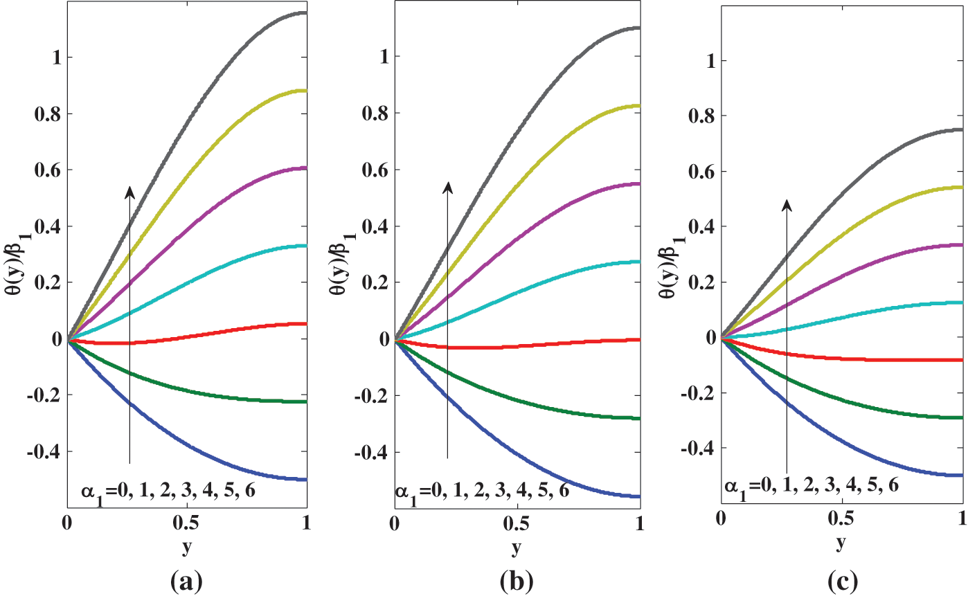
Figure 6: Temperature profile for different values of
Eq. (36) and Fig. 6c both align with Eq. (12) and Fig. 3a of [10]. Figs. 6a and 6b are plotted for micropolar fluid. These figures show that (i) the temperature increases across the channel as the micropolarity increases, due to the collides in the fluid, the thermal flux rises; (ii) the temperature for micropolar fluid is greater than the temperature for the Newtonian fluid consistently by the increase in the kinetic energy of the aciculate particles in the micropolar fluid; (iii) the temperature
The variation of temperature at the air-nano micropolar fluid interface is important techno-scientifically. It is examined by focusing on variation of

These tables show clearly the comparison between micropolar and Newtonian fluids. Table 3 depicts that the temperature
The thermal transfer rate is significant in engineering and technology. It is studied in terms of the Nusselt number
If Eqs. (19)–(21) are substituted in Eq. (38), then one yields
where
The results related to the Nusselt number are shown quantitatively in Table 4 while qualitatively in Fig. 7a. Through Table 4 and Fig. 7a, it is observed that

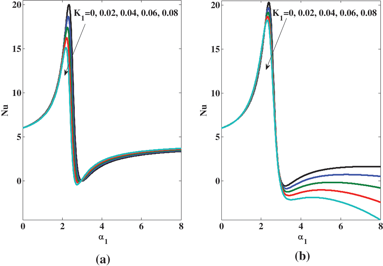
Figure 7: Variation of the Nusselt number
4.4 Influence of Nanoparticles
Let us define the following two important ratios to highlight the influences of nanoparticles [10]:
There are five different types of samples of nanoparticles in order to examine in this current study, namely gold
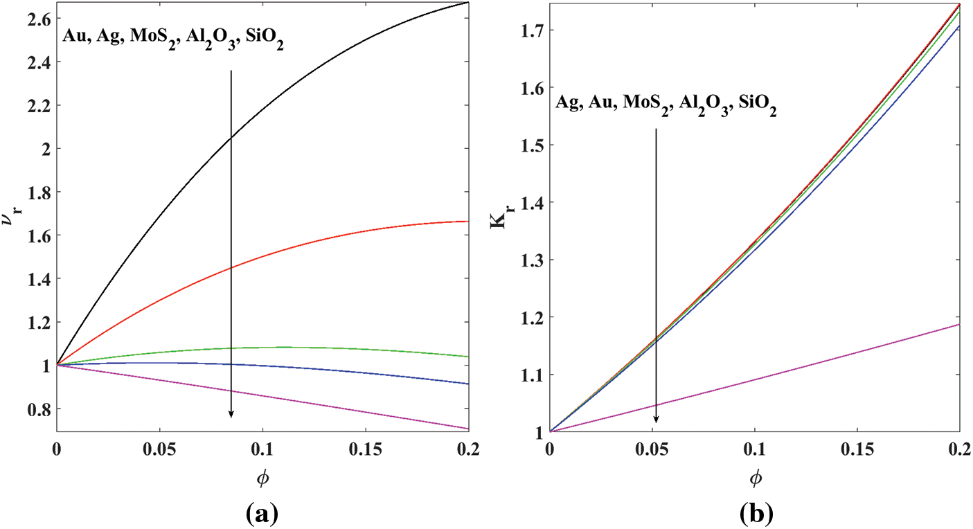
Figure 8: Effects of the concentration of nanoparticles
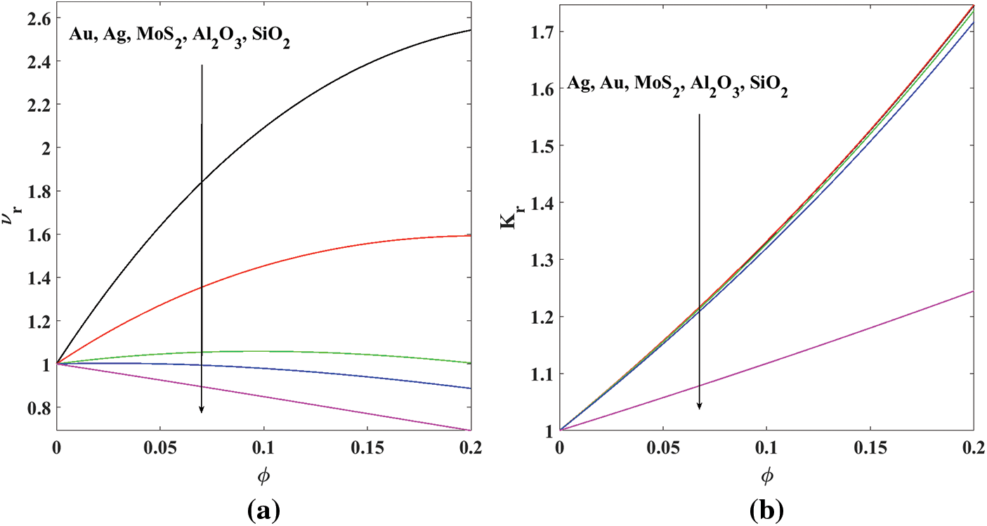
Figure 9: Effects of the concentration of nanoparticles
The concentration of nanoparticles
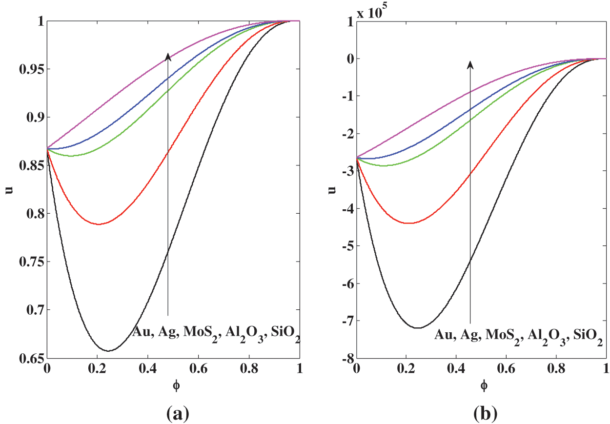
Figure 10: Midpoint channel effects of the concentration of nanoparticles
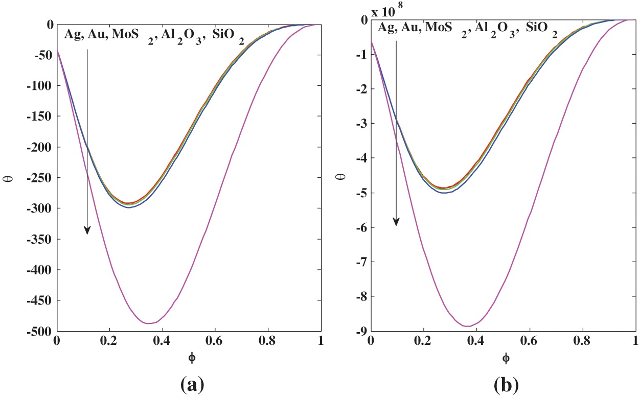
Figure 11: Midpoint channel effects of the concentration of nanoparticles
In this study, the thin film flow of a micropolar fluid containing nanoparticles over an inclined substrate under the influence of viscous dissipation and gravitational force was formulated and examined theoretically. An exact solution to the formulated boundary value problem was derived for the first time. The variation of physical quantities, fluid speed, temperature, and microrotation/spin was analyzed based on the solution. The results are displayed in graphical and tabular form and compared to existing results from the literature for the Newtonian fluid as a particular case of the current study.
The results showed that the fluid velocity declines with increasing values of spin boundary condition and micropolarity due to the increase in colloids in the micropolar medium. Additionally, micropolarity with spin leads to an enhanced temperature field compared to a Newtonian fluid. Furthermore, it is observed that the Nusselt number rises until it reaches an amplitude that varies with micropolarity effects. Mid velocities eventually reveal a quantitative decay in a micropolar fluid compared to a Newtonian one for all tested nanoparticles, with similar behavior in temperature at the mid-channel. Gold and silver nanoparticles (i) intensify the flow parameters as the concentration of nanoparticles increases (ii) yield a higher thermal transfer rate, whereas molybdenum disulfide, aluminum oxide, and silicon dioxide exhibit the opposite behavior; this holds true for both Newtonian and micropolar fluids. Moreover, a reduction in film thickness for nano-liquid-containing gold particles, compared to other nanoparticles, is observed. Finally, it is important to state that this work is new and original.
Acknowledgement: The authors are extremely grateful to the editor of the journal and all four reviewers for very useful comments and suggestions.
Funding Statement: The authors did not receive any funding support from any source. It is self-financed solely.
Author Contributions: AAS: Conceptualization, Modeling, Calculations, Writing, Software; MT: Potential review, Keen validation, Proof reading, Collection of useful data, Valuable suggestions.
Availability of Data and Materials: MatLab was used to simulate the results. Upon reasonable request.
Conflicts of Interest: The authors have no conflict of interest to report regarding the present study.
References
1. Bertozzi AL, Pugh M. The lubrication approximation for thin viscous films: regularity and long-time behavior of weak solutions. Commun Pure Appl Math. 1996 Feb;49(2):85–123. doi:10.1002/(ISSN)1097-0312. [Google Scholar] [CrossRef]
2. Roy RV, Roberts AJ, Simpson ME. A lubrication model of coating flows over a curved substrate in space. J Fluid Mech. 2002 Mar;454:235–61. doi:10.1017/S0022112001007133. [Google Scholar] [CrossRef]
3. Dutta A, Som SK, Das PK. Film condensation of saturated vapor over horizontal noncircular tubes with progressively increasing radius of curvature drawn in the direction of gravity. J Heat Transfer. 2004 Dec 1;126(6):906–14. doi:10.1115/1.1798891. [Google Scholar] [CrossRef]
4. Taherzadeh D. Mechanics and substrate transport of moving biofilm structures (Ph.D. Thesis). Technische Universität München: Germany; 2011. [Google Scholar]
5. Howell PD, Robinson J, Stone HA. Gravity-driven thin-film flow on a flexible substrate. J Fluid Mech. 2013 Oct;732:190–213. doi:10.1017/jfm.2013.404. [Google Scholar] [CrossRef]
6. Liu Y, Itoh M, Kyotoh H. Flow of a falling liquid curtain onto a moving substrate. Fluid Dyn Res. 2017 Jul 27;49(5):055501. doi:10.1088/1873-7005/aa7ee8. [Google Scholar] [CrossRef]
7. Girtan M. Future solar energy devices. In: SpringerBriefs in applied sciences and technology. Cham: Springer; 2018. p. 1–104. doi:10.1007/978-3-319-67337-0. [Google Scholar] [CrossRef]
8. Thiele U. Recent advances in and future challenges for mesoscopic hydrodynamic modelling of complex wetting. Colloids Surf A: Physicochem Eng Asp. 2018 Sep 20;553:487–95. doi:10.1016/j.colsurfa.2018.05.049. [Google Scholar] [CrossRef]
9. Kreder MJ, Daniel D, Tetreault A, Cao Z, Lemaire B, Timonen JV, et al. Film dynamics and lubricant depletion by droplets moving on lubricated surfaces. Phys Rev X. 2018 Sep 4;8(3):031053. [Google Scholar]
10. Turkyilmazoglu M. Nanoliquid film flow due to a moving substrate and heat transfer. Eur Phys J Plus. 2020 Oct 6;135(10):781. doi:10.1140/epjp/s13360-020-00812-y. [Google Scholar] [CrossRef]
11. Girtan M. On the electrical and photoelectrical properties of CH3NH3PBI3 perovskites thin films. Sol Energy. 2020 Jan 1;195:446–53. doi:10.1016/j.solener.2019.11.096. [Google Scholar] [CrossRef]
12. Halpern D, Grotberg JB. Fluid-elastic instabilities of liquid-lined flexible tubes. J Fluid Mech. 1992 Nov;244:615–32. doi:10.1017/S0022112092003227. [Google Scholar] [CrossRef]
13. Heil M, White JP. Airway closure: surface-tension-driven non-axisymmetric instabilities of liquid-lined elastic rings. J Fluid Mech. 2002 Jul;462:79–109. doi:10.1017/S0022112002008613. [Google Scholar] [CrossRef]
14. Qayyum M, Ismail F, Sohail M, Imran N, Askar S, Park C. Numerical exploration of thin film flow of MHD pseudo-plastic fluid in fractional space: utilization of fractional calculus approach. Open Phys. 2021 Nov 26;19(1):710–21. doi:10.1515/phys-2021-0081. [Google Scholar] [CrossRef]
15. Adesanya SO, Onanaye AS, Adeyemi OG, Rahimi-Gorji M, Alarifi IM. Evaluation of heat irreversibility in couple stress falling liquid films along heated inclined substrate. J Clean Prod. 2019 Dec 1;239:117608. doi:10.1016/j.jclepro.2019.117608. [Google Scholar] [CrossRef]
16. Waini I, Ishak A, Pop I. Radiative and magnetohydrodynamic micropolar hybrid nanofluid flow over a shrinking sheet with Joule heating and viscous dissipation effects. Neural Comput Appl. 2022 Mar;34(5):3783–94. doi:10.1007/s00521-021-06640-0. [Google Scholar] [CrossRef]
17. Bilal M, Ramzan M, Siddique I, Sajjad A. Magneto-micropolar nanofluid flow through the convective permeable channel using Koo-Kleinstreuer–Li model. J Magn Magn Mater. 2023 Jan 1;565:170288. doi:10.1016/j.jmmm.2022.170288. [Google Scholar] [CrossRef]
18. Rajkumar D, Reddy AS, Narayana PS, Jagadeshkumar K, Chamkha AJ. Pulsating magnetohydrodynamic flow of Fe3O4-blood based micropolar nanofluid between two vertical porous walls with Cattaneo-Christov heat flux and entropy generation. J Magn Magn Mater. 2023 Apr 1;571:170564. doi:10.1016/j.jmmm.2023.170564. [Google Scholar] [CrossRef]
19. Bayareh M. An overview of non-Newtonian nanofluid flow in macro-and micro-channels using two-phase schemes. Eng Anal Bound Elem. 2023 Mar 1;148:165–75. doi:10.1016/j.enganabound.2022.12.033. [Google Scholar] [CrossRef]
20. Nabwey HA, Rahbar F, Armaghani T, Rashad AM, Chamkha AJ. A comprehensive review of non-newtonian nanofluid heat transfer. Symmetry. 2023 Jan 29;15(2):362. doi:10.3390/sym15020362. [Google Scholar] [CrossRef]
21. Siddiqui AA, Lakhtakia A. Steady electro-osmotic flow of a micropolar fluid in a microchannel. Proc R Soc A: Math, Phys Eng Sci. 2009 Feb 8;465(2102):501–22. doi:10.1098/rspa.2008.0354. [Google Scholar] [CrossRef]
22. Siddiqui AA, Turkyilmazoglu M. Slit flow and thermal analysis of micropolar fluids in a symmetric channel with dynamic and permeable. Int Commun Heat Mass Transf. 2022 Mar 1;132:105844. doi:10.1016/j.icheatmasstransfer.2021.105844. [Google Scholar] [CrossRef]
23. Nusselt W. Die oberflachenkondensation des wasserdamphes. VDI-Zs. 1916;60:541. [Google Scholar]
24. Tamir A, Taitel Y. Nusselt condensation with interfacial resistance. Chem Eng J. 1974 Jan 1;7(3):245–7. doi:10.1016/0300-9467(74)85038-0. [Google Scholar] [CrossRef]
25. Kondic L, Diez J. Pattern formation in the flow of thin films down an incline: constant flux configuration. Phys Fluids. 2001 Nov 1;13(11):3168–84. doi:10.1063/1.1409965. [Google Scholar] [CrossRef]
26. O’Brien SBG, Schwartz LW. Theory and modeling of thin film flows. 2002. Available from: https://api.semanticscholar.org/CorpusID:11512995. [Accessed 2023]. [Google Scholar]
27. Wang H, Rose JW. Film condensation in horizontal microchannels: effect of channel shape. Int Conf Nanochannels, Microchannels, Minichannels. 2005 Jan 1;41855:729–35. [Google Scholar]
28. Al-Jarrah JA, Khadrawi AF, Al-Nimr MA. Film condensation on a vertical microchannel. Int Commun Heat Mass Transf. 2008 Nov 1;35(9):1172–6. doi:10.1016/j.icheatmasstransfer.2008.07.003. [Google Scholar] [CrossRef]
29. Gatapova EY, Kabov OA. Shear-driven flows of locally heated liquid films. Int J Heat Mass Transf. 2008 Sep 1;51(19–20):4797–810. [Google Scholar]
30. Lin TS, Kondic L, Filippov A. Thin films flowing down inverted substrates: three-dimensional flow. Phys Fluids. 2012;24:022105. doi:10.1063/1.3682001. [Google Scholar] [CrossRef]
31. Mazloomi A, Moosavi A. Thin liquid film flow over substrates with two topographical features. Phys Rev E. 2013 Feb 26;87(2):022409. doi:10.1103/PhysRevE.87.022409. [Google Scholar] [CrossRef]
32. Slade DR. Gravity-driven thin liquid films: rivulets and flow dynamics. England, UK: University of Leeds; 2013. [Google Scholar]
33. Ju W, Wu Y, Lin S, Zhao F, Tan S. Visual experimental study of droplet impinging on liquid film and analysis of droplet evolution characteristics. Exp Comput Multiph Flow. 2022;4(3):212–20. doi:10.1007/s42757-020-0081-3. [Google Scholar] [CrossRef]
34. Charogiannis A, Markides CN. Spatiotemporally resolved heat transfer measurements in falling liquid-films by simultaneous application of planar laser-induced fluorescence (PLIFparticle tracking velocimetry (PTV) and infrared (IR) thermography. Exp Therm Fluid Sci. 2019 Oct 1;107:169–91. doi:10.1016/j.expthermflusci.2018.11.001. [Google Scholar] [CrossRef]
35. Wang XF, Hrnjak PS, Elbel S, Jacobi AM, He MG. Heat transfer performance for a falling-film on horizontal flat tubes. J Heat Transf. 2013 Jul 1;135(7):072901. doi:10.1115/1.4023689. [Google Scholar] [CrossRef]
36. Budakli M. Hydrodynamics and heat transfer in gas-driven liquid film flows (Ph.D. Thesis). Institute of Technical Thermodynamics, Technische Universitat Darmstadt: Germany; 2015. [Google Scholar]
37. Markides CN, Mathie R, Charogiannis A. An experimental study of spatiotemporally resolved heat transfer in thin liquid-film flows falling over an inclined heated foil. Int J Heat Mass Transf. 2016 Feb 1;93:872–88. doi:10.1016/j.ijheatmasstransfer.2015.10.062. [Google Scholar] [CrossRef]
38. Miladinova S, Lebon G, Toshev E. Thin-film flow of a power-law liquid falling down an inclined plate. J Non-Newton Fluid Mech. 2004 Sep 20;122(1–3):69–78. [Google Scholar]
39. Siddiqui AM, Mahmood R, Ghori QK. Some exact solutions for the thin film flow of a PTT fluid. Phys Lett A. 2006 Aug 14;356(4–5):353–6. [Google Scholar]
40. Siddiqui AM, Mahmood R, Ghori QK. Homotopy perturbation method for thin film flow of a fourth grade fluid down a vertical cylinder. Phys Lett A. 2006 Apr 3;352(4–5):404–10. [Google Scholar]
41. Siddiqui AM, Mahmood R, Ghori QK. Homotopy perturbation method for thin film flow of a third grade fluid down an inclined plane. Chaos, Solitons Fractals. 2008 Jan 1;35(1):140–7. doi:10.1016/j.chaos.2006.05.026. [Google Scholar] [CrossRef]
42. Alam MK, Siddiqui AM, Rahim MT, Islam S, Avital EJ, Williams JJ. Thin film flow of magnetohydrodynamic (MHD) pseudo-plastic fluid on vertical wall. Appl Math Comput. 2014 Oct 15;245:544–56. [Google Scholar]
43. Singh J, Kumar D, Baleanu D. A hybrid analytical algorithm for thin film flow problem occurring in non-Newtonian fluid mechanics. Ain Shams Eng J. 2021 Jun 1;12(2):2297–302. doi:10.1016/j.asej.2020.09.006. [Google Scholar] [CrossRef]
44. Tlili I, Samrat SP, Sandeep N, Nabwey HA. Effect of nanoparticle shape on unsteady liquid film flow of MHD Oldroyd-B ferrofluid. Ain Shams Eng J. 2021 Mar 1;12(1):935–41. doi:10.1016/j.asej.2020.06.007. [Google Scholar] [CrossRef]
45. Abdal S, Siddique I, Salamat N, Ud Din IS. Nano-bio-film flow of Williamson fluid due to a non-linearly extending/contracting surface with non-uniform physical properties. Waves Random Complex Media. 2022 Nov 16;1–9. doi:10.1080/17455030.2022.2146233. [Google Scholar] [CrossRef]
46. Alali E, Megahed AM. MHD dissipative Casson nanofluid liquid film flow due to an unsteady stretching sheet with radiation influence and slip velocity phenomenon. Nanotechnol Rev. 2022 Jan 15;11(1):463–72. doi:10.1515/ntrev-2022-0031. [Google Scholar] [CrossRef]
47. Esmaeili E, Grassia P, Ulloa CAT. Squeeze film flow of viscoplastic Bingham fluid between non-parallel plates. J Non-Newton Fluid Mech. 2022 Jul 1;305:104817. doi:10.1016/j.jnnfm.2022.104817. [Google Scholar] [CrossRef]
48. Qayyum M, Ismail F, Ali Shah SI, Sohail M, El-Zahar ER, Gokul KC. An application of homotopy perturbation method to fractional-order thin film flow of the Johnson-Segalman fluid model. Math Probl Eng. 2022 Feb 23;2022:1–7. [Google Scholar]
49. Hassan MH, Al-Saif AS. A mathematical model for the velocity of thin film flow of a third grade fluid down in an inclined plane. J Adv Res Fluid Mech Therm Sci. 2023 Feb 13;102(1):140–52. doi:10.37934/arfmts. [Google Scholar] [CrossRef]
50. Ashraf H, Sabir S, Siddiqui AM, Rehman HU, Almutairi B, Shah NA. Heat transfer analysis of temperature dependent viscosity Johnson-Segalman fluid film flow on a vertical heated belt. Case Stud Therm Eng. 2023 Sep 1;49:103362. doi:10.1016/j.csite.2023.103362. [Google Scholar] [CrossRef]
51. Mahesh T, Panda S. Longwave modeling of thin film flow of a generalized second-grade fluid down a slanted plate. Int J Non Linear Mech. 2023 Mar 1;149:104327. doi:10.1016/j.ijnonlinmec.2022.104327. [Google Scholar] [CrossRef]
52. Mandal S, Shit GC. Entropy analysis of unsteady magnetohydrodynamic thin liquid film flow of Maxwell nanofluids with variable fluid properties. Mater Chem Phys. 2023 Jan 1;293:126890. doi:10.1016/j.matchemphys.2022.126890. [Google Scholar] [CrossRef]
53. Vanitha GP, Shobha KC, Mallikarjun BP, Mahabaleshwar US, Bognár G. Casson nanoliquid film flow over an unsteady moving surface with time-varying stretching velocity. Sci Rep. 2023 Mar 11;13(1):4074. doi:10.1038/s41598-023-30886-4. [Google Scholar] [CrossRef]
54. Turk MA, Sylvester ND, Ariman T. On pulsatile blood flow. Trans Soc Rheol. 1973 Mar 1;17(1):1–21. doi:10.1122/1.549295. [Google Scholar] [CrossRef]
55. Misra JC, Ghosh SK. A mathematical model for the study of interstitial fluid movement vis-a-vis the non-Newtonian behaviour of blood in a constricted artery. Comput Math Appl. 2001 Mar 1;41(5–6):783–811. [Google Scholar]
56. Eringen AC. Microcontinuum field theories: II. fluent media. London, UK: Springer Science & Business Media; 2001 Mar 30. [Google Scholar]
57. Papautsky I, Brazzle J, Ameel T, Frazier AB. Laminar fluid behavior in microchannels using micropolar fluid theory. Sens Actuators A: Phys. 1999 Mar 9;73(1–2):101–8. [Google Scholar]
58. Yusuf TA, Kumar RN, Prasannakumara BC, Adesanya SO. Irreversibility analysis in micropolar fluid film along an incline porous substrate with slip effects. Int Commun Heat Mass Transf. 2021 Jul 1;126:105357. doi:10.1016/j.icheatmasstransfer.2021.105357. [Google Scholar] [CrossRef]
59. Ahmad S, Naveed Khan M, Ali R, Ahmad Lone S. Analysis of free bioconvective flow of hybrid nanofluid induced by convectively heated cone with entropy generation. Mod Phys Lett B. 2024 Jan 30;38(03):2450015. doi:10.1142/S0217984924500155. [Google Scholar] [CrossRef]
60. Ali L, Ali B, Iqbal T. Finite element analysis of the impact of particles aggregation on the thermal conductivity of nanofluid under chemical reaction. Waves Random Complex Media. 2023 Feb 4;1–21. [Google Scholar]
61. Shah SA, Ahammad NA, Ali B, Guedri K, Awan AU, Gamaoun F, et al. Significance of bio-convection, MHD, thermal radiation and activation energy across Prandtl nanofluid flow: a case of stretching cylinder. Int Commun Heat Mass Transf. 2022 Oct 1;137:106299. doi:10.1016/j.icheatmasstransfer.2022.106299. [Google Scholar] [CrossRef]
62. Abbas N, Rehman KU, Shatanawi W, Abodayeh K. Mathematical model of temperature-dependent flow of power-law nanofluid over a variable stretching Riga sheet. Waves Random Complex Media. 2022 Aug 18;1–8. doi:10.1080/17455030.2022.2111029. [Google Scholar] [CrossRef]
63. Stfytfkora D, Kašička V, Mikšík I, Řezanka P, Záruba K, Matějka P, et al. Application of gold nanoparticles in separation sciences. J. Sep. Sci. 2010 Feb;33(3):372–87. doi:10.1002/jssc.v33:3. [Google Scholar] [CrossRef]
64. Cabuzu D, Cirja A, Puiu R, Mihai Grumezescu A. Biomedical applications of gold nanoparticles. Curr Top Med Chem. 2015 Aug 1;15(16):1605–13. doi:10.2174/1568026615666150414144750. [Google Scholar] [CrossRef]
65. Zaaroura I, Harmand S, Carlier J, Toubal M, Fasquelle A, Nongaillard B. Thermal performance of self-rewetting gold nanofluids: application to two-phase heat transfer devices. Int J Heat Mass Transf. 2021 Aug 1;174:121322. doi:10.1016/j.ijheatmasstransfer.2021.121322. [Google Scholar] [CrossRef]
66. Hao D, Yang R, Yi N, Cheng H. Highly sensitive piezoresistive pressure sensors based on laser-induced graphene with molybdenum disulfide nanoparticles. Sci China Technol Sci. 2021 Nov;64(11):2408–14. doi:10.1007/s11431-021-1899-9. [Google Scholar] [CrossRef]
67. Luo SW, Alimujiang A, Cui J, Chen TT, Balamurugan S, Zheng JW, et al. Molybdenum disulfide nanoparticles concurrently stimulated biomass and β-carotene accumulation in Dunaliella salina. Bioresour Technol. 2021 Jan 1;320:124391. doi:10.1016/j.biortech.2020.124391. [Google Scholar] [CrossRef]
68. Gudkov SV, Burmistrov DE, Smirnova VV, Semenova AA, Lisitsyn AB. A mini review of antibacterial properties of Al2O3 nanoparticles. Nanomater. 2022 Jul 30;12(15):2635. doi:10.3390/nano12152635. [Google Scholar] [CrossRef]
69. Wei J, He C, Lv G, Zhuang Y, Qian Y, Pan S. The combustion, performance and emissions investigation of a dual-fuel diesel engine using silicon dioxide nanoparticle additives to methanol. Energy. 2021 Sep 1;230:120734. doi:10.1016/j.energy.2021.120734. [Google Scholar] [CrossRef]
70. Shuai C, Yang F, Shuai Y, Peng S, Chen S, Deng Y, et al. Silicon dioxide nanoparticles decorated on graphene oxide nanosheets and their application in poly(l-lactic acid) scaffold. J Adv Res. 2023 Jun 1;48:175–90. doi:10.1016/j.jare.2022.08.017. [Google Scholar] [CrossRef]
71. Nield DA, Kuznetsov AV. Forced convection in a parallel-plate channel occupied by a nanofluid or a porous medium saturated by a nanofluid. Int J Heat Mass Transf. 2014 Mar 1;70:430–3. doi:10.1016/j.ijheatmasstransfer.2013.11.016. [Google Scholar] [CrossRef]
72. Ilyas SU, Pendyala R, Marneni N. Stability of nanofluids. In: Engineering applications of nanotechnology: from energy to drug delivery. Springer International Publishing; 2017. p. 1–31. [Google Scholar]
73. Khan MR, Puneeth V, Alqahtani AM, Alhazmi SE, Beinane SA, Shutaywi M, et al. Numerical simulation and mathematical modeling for heat and mass transfer in MHD stagnation point flow of nanofluid consisting of entropy generation. Sci Rep. 2023 Apr 19;13(1):6423. doi:10.1038/s41598-023-33412-8. [Google Scholar] [CrossRef]
Cite This Article
 Copyright © 2024 The Author(s). Published by Tech Science Press.
This work is licensed under a Creative Commons Attribution 4.0 International License , which permits unrestricted use, distribution, and reproduction in any medium, provided the original work is properly cited.


 Submit a Paper
 Propose a Special lssue
 View Full Text
 Download PDF
 Downloads
 Citation Tools