
 Submit a Paper
 Propose a Special lssue
 Open Access
ARTICLE

A Multiscale Reliability-Based Design Optimization Method for Carbon-Fiber-Reinforced Composite Drive Shafts
1 Yangtze Delta Region Institute (Huzhou), University of Electronic Science and Technology of China, Huzhou, 313001, China
2 Huzhou Key Laboratory of Green Energy Materials and Battery Cascade Utilization, Huzhou College, Huzhou, 313000, China
3 SAIC Motor Corporation Limited Passenger Vehicle Co., Shanghai, 201804, China
4 School of Mechanical and Electrical Engineering, University of Electronic Science and Technology of China,
Chengdu, 611731, China
* Corresponding Authors: Huile Zhang. Email: ; Zhonglai Wang. Email:
(This article belongs to the Special Issue: Structural Design and Optimization)
Computer Modeling in Engineering & Sciences 2024, 140(2), 1975-1996. https://doi.org/10.32604/cmes.2024.050185
Received 30 January 2024; Accepted 01 April 2024; Issue published 20 May 2024
 View Full Text
 Download PDF
Abstract
Carbon fiber composites, characterized by their high specific strength and low weight, are becoming increasingly crucial in automotive lightweighting. However, current research primarily emphasizes layer count and orientation, often neglecting the potential of microstructural design, constraints in the layup process, and performance reliability. This study, therefore, introduces a multiscale reliability-based design optimization method for carbon fiber-reinforced plastic (CFRP) drive shafts. Initially, parametric modeling of the microscale cell was performed, and its elastic performance parameters were predicted using two homogenization methods, examining the impact of fluctuations in microscale cell parameters on composite material performance. A finite element model of the CFRP drive shaft was then constructed, achieving parameter transfer between microscale and macroscale through Python programming. This enabled an investigation into the influence of both micro and macro design parameters on the CFRP drive shaft’s performance. The Multi-Objective Particle Swarm Optimization (MOPSO) algorithm was enhanced for particle generation and updating strategies, facilitating the resolution of multi-objective reliability optimization problems, including composite material layup process constraints. Case studies demonstrated that this approach leads to over 30% weight reduction in CFRP drive shafts compared to metallic counterparts while satisfying reliability requirements and offering insights for the lightweight design of other vehicle components.Keywords
Lured by the high specific strength, lightweight nature, and relatively high resistance to corrosion of carbon fiber-reinforced composites, these materials have seen extensive research and attention within the automotive industry [1–5]. Bambach [6] significantly enhanced the strength of passenger vehicle roof structures by incorporating carbon fiber into their components. With the framework of bending stiffness requirements, Lee et al. [7] developed, manufactured, and validated the effectiveness of a carbon fiber-reinforced plastic (CFRP) roof panel. Liu et al. [8] examined an investigation into the dynamic impact responses of CFRP header rails, employing both experimental and numerical methods. However, although the studies mentioned primarily concentrate on reengineering vehicle parts, research specifically directed toward drive shafts is relatively rare.
Abu Talib et al. [9] developed a hybrid automotive drive shaft using carbon/glass fiber-reinforced epoxy composites and utilized finite element analysis (FEA) to assess the impact of fiber orientation and layup sequence on mechanical properties and fatigue resistance. Sun et al. [10] investigated the vibration performance of CFRP drive shafts integrated with metal flanges and produced through filament winding, employing both theoretical and numerical analyses to evaluate various layup sequence schemes. Soliman et al. [11] performed a comparative analysis of various layup sequence strategies for carbon fiber drive shafts, demonstrating that optimization of these sequences can significantly enhance torsional stiffness. However, a crucial aspect of CFRP is its customizable microstructure in manufacturing, determined by the choice of components (reinforcement and matrix) and the arrangement of layers [12,13]. While prior studies have focused on layer number and orientation, they have not fully explored microstructure design potential. Fortunately, Liu et al. [14] employed a multiscale analysis method to develop a CFRP-based electric vehicle structure, achieving a significant 28% weight reduction. Cheng et al. [15] combined microscale homogenization with macroscale optimization, resulting in a remarkable 60% reduction in the weight of the body-in-white floor’s lightweight design. By integrating multiscale numerical simulations with experimental testing, Fang et al. [16] carried out comprehensive analyses of the mechanical properties of single-ply woven composite materials. Despite the proven effectiveness of multiscale CFRP design approaches, practical design scenarios are often fraught with uncertainties related to loads, material attributes, and geometric factors. Neglecting these uncertainties can lead to designs that are unreliable or unstable, consequently escalating the risk of design failures [17,18].
Zhou et al. [19] examined the benefits of multiscale analysis in reliability assessments for composite structures, illustrating that this method offers more accurate reliability estimates. Liu et al. [20] successfully executed a multiscale reliability design for a CFRP battery box cap, achieving a significant 22.14% weight reduction while ensuring high reliabilities for all performance indices. Omairey et al. [21] established an efficient surrogate modeling framework to capture multiscale uncertainties in continuous fiber-reinforced composites. Sun et al. [22] performed multiscale uncertainty propagation analysis and reliability optimization on the CFRP crossbeam of a twist-beam axle, leading to a notable 46.96% mass reduction compared to the steel equivalent, with considerable improvements in other performance parameters. Yet, the majority of such research fails to sufficiently account for the process limitations associated with CFRP layup angles, leading to optimization outcomes that might not adhere to these restrictions, thereby requiring additional adjustments for real-world engineering implementations.
To fully leverage the potential for microstructural design of CFRP, while considering layup process constraints and the reliability of performance indicators, this study proposes a multiscale reliability-based design optimization method, applied in real-world CFRP drive shaft development. The structure of this paper is organized as follows: Section 2 discusses the microscale analysis methods for the CFRP drive shaft, offering an in-depth parameter analysis. Section 3 delves into the loading conditions, constraints, and performance criteria relevant to the design of CFRP drive shafts. Section 4 elaborates on the mathematical modeling and the algorithm for the multiscale reliability-based design optimization of the CFRP drive shaft, subsequently demonstrating the obtained results and providing a detailed analysis. Finally, the paper summarizes the main conclusions derived from this research.
2 Multiscale Modeling of Carbon-Fiber-Reinforced Composite
2.1 An Overview of Multiscale Modeling for Carbon-Fiber-Reinforced Composites
The multiscale design of unidirectional carbon fiber-reinforced composites encompasses both microscale and macroscale levels, as illustrated in Fig. 1. At the microscale level, the microscale cell, composed of fiber filaments and resin, is homogenized from the cross-sectional image obtained through electron microscopy. Herein, the fiber filaments primarily bear the load, while the resin matrix facilitates load transfer. At the macroscale level, the laminates are formed by bonding single-layer unidirectional composite materials with a small amount of resin. As evident in Fig. 1, the performance of composite material components is influenced by multiple factors, including layer thickness, lay-up angle, layer count, as well as the mechanical properties and volume fractions of fibers and resin. Consequently, the structural design of carbon fiber-reinforced composites is inherently a multiscale task. This section elaborates on the homogenization approaches used for evaluating the elastic properties at the microscale cell, including the boundary force-based homogenization method and the thermal stress-based homogenization method.
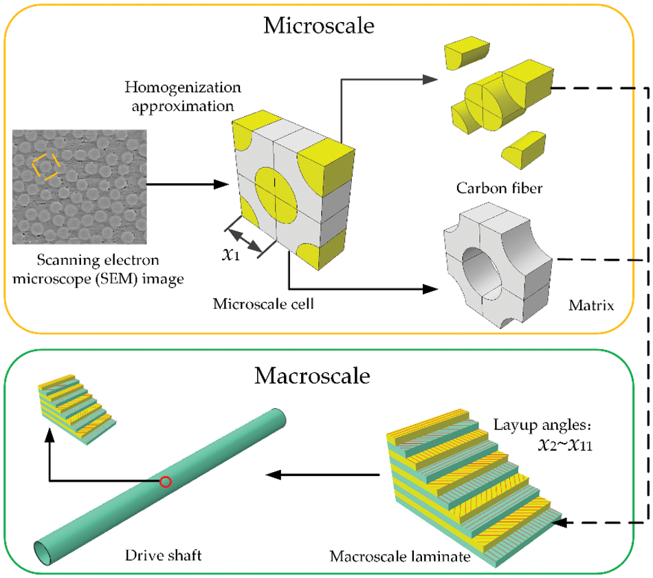
Figure 1: Flow chart of multiscale design for CFRP drive shafts
2.1.1 Boundary Force-Based Homogenization Method
In addition to traditional theoretical analysis methods, the method of simulating the mechanical properties of composite materials through finite element analysis, by imposing appropriate boundary conditions on a unit cell, has gained increasing popularity [13]. This section introduces the boundary force-based homogenization method [23].
Unidirectional composite materials are typical orthotropic materials, and their constitutive equations are as follows:
where
The macroscopic stress and strain tensors can be obtained through numerical calculations on the unit cell, derived from the average stress and average strain. The mathematical expressions for the average stress tensor
where V represents the volume of the unit cell.
To calculate the compliance matrix in the finite element model of the unit cell, a constant non-zero displacement component is sequentially applied on a specific surface, while imposing appropriate compatibility constraints on the other surfaces [23]. Utilizing finite element analysis, it is possible to resolve the stresses and strains at integration points in various directions under differing boundary conditions. Consequently, the average stress tensor
2.1.2 Thermal Stress-Based Homogenization Method
The use of linear perturbation techniques for solving two-scale progressive homogenization method has been reported as feasible and is suitable for addressing multiscale analysis problems in carbon fiber-reinforced composites [15,25]. Utilizing FEA tools, the unit cell is subjected to thermal stress to estimate its elastic properties. The formula for determining the stiffness coefficients is presented below:
In this formula,
To calculate the stiffness matrix as outlined in Eq. (3), the first task is to compute the displacement function. By subjecting it to thermal stress, one can derive the solution for the displacement function. Following a theoretical analysis, this function can be redefined using the thermal expansion coefficient, as demonstrated in the subsequent equation:
In this context,
The approach is executed in the following manner: Periodic boundary conditions (PBC) are established using Multi-Point Constraints. Thermal stress application is achieved through a Fortran subroutine, and a Python script is crafted for the extraction of stress-strain information, thereby aiding in the determination of homogenization coefficients. Given the limitation of space, this document refrains from an in-depth exploration of the homogenization techniques; nevertheless, readers seeking additional insights are advised to explore the pertinent academic resources [23,25].
2.2 Microscale Model Simulation Analysis
To realize the multiscale reliability design of CFRP drive shafts, it is crucial to explore the microscale properties of CFRP. Consequently, this section presented a comprehensive study on the microscale cell, including methods for establishing microscale cells, the impact of microscale parameters on the elastic properties, and the influence of design parameter uncertainty on the elastic properties.
2.2.1 Microscale Model Simulation Analysis Method
To develop a realistic microscale model, the cross-section of unidirectional CFRP was examined using an electron microscope (model JSM-IT300LA), as shown in Fig. 2. This cross-section was then represented as an equivalent microscale cell using a homogenization method. It is crucial to note that the selection of microscale cell types for unidirectional fiber composite, guided by the principle of periodic arrangement, is not unique. As depicted in Fig. 2, it is possible to distinguish five distinct cell structures, labeled C1 to C5. A key shared feature among these structures is their fiber volume fraction, which is approximately 51% in each case. This section will specifically focus on the modeling methodology for the microscale cell, using C5 as a representative example. Fig. 1 illustrates the critical geometric dimensions of the C5, encompassing the fiber filaments’ diameter, the thickness of the cell, and the half-side length denoted as (x1). Research documented in references [26,27] highlights that the fiber volume fraction (Vf) plays a pivotal role in determining the elastic characteristics of the microscale cell structure. Consequently, this research maintains the diameter of the fiber and the thickness of the cell as fixed parameters, manipulating the microscale cell’s half-side length to achieve various Vf values.
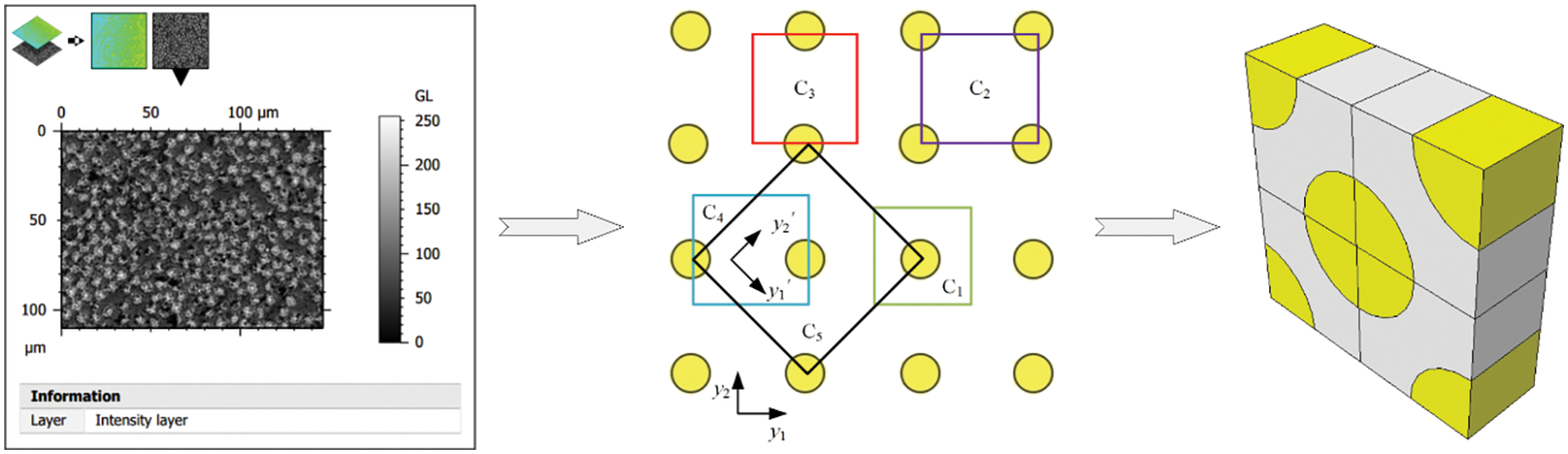
Figure 2: Schematic view of microscale cell construction
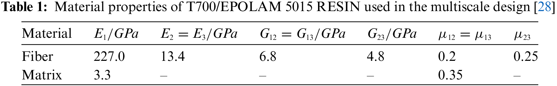
This study employed T700-12k carbon fibers and chose EPOLAM 5015 RESIN as the matrix material. The mechanical characteristics of both the carbon fibers and the resin have already been determined by experiments in our previous research [28]. In order to improve the readability of the paper, the specific data are comprehensively included in Table 1.
To predict the elastic properties of CFRP, the microscale cell model C5 was developed in ABAQUS, as shown in Fig. 2. The specific analysis procedure followed these steps: Firstly, the geometric model of the microscale cell was established, secondly, the material properties from Table 1 were assigned to the fibers and resin of the microscale cell, with material orientations being specified, The mesh was then generated using C3D8R elements, and the application of loads and solving were conducted as outlined in Section 2.1. Specifically, to obtain convergent analysis results, meshes of sizes 0.2, 0.4, 0.6, 0.8, and 1 mm were examined, as depicted in Fig. 3, and both boundary force-based and thermal stress-based homogenization analyses were performed. The findings, presented in Table 2, reveal that at a mesh size of 0.4 mm, the elastic parameters obtained from both analysis methods tend to converge. Therefore, a mesh size of 0.4 mm was selected for this study. To observe the stress distribution of the microscale cell under different thermal stress loading conditions, Fig. 4 presents the stress distribution contour maps for six different loading scenarios. S11, S22, and S33 illustrate the tensile states of microscale cells. As shown in S11, under axial tension conditions, the fibers bear the primary load. S22 and S33 demonstrate that the contour plots are rotationally symmetric along the fiber direction. S12, S13, and S23 present the shear states of the microscale cells. It can be observed from S12 and S13 that the contour plot distribution is rotationally symmetric along the fiber direction. In summary, the aforementioned analysis indirectly validates the reliability of the multiscale analysis method proposed in this paper.
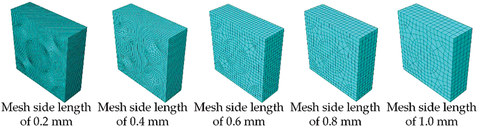
Figure 3: Schematic view of microscale cell models with different mesh sizes


Figure 4: Equivalent stress contour result of different thermal stress conditions
To investigate the influence of microscale cell type on the elastic properties of unidirectional CFRP, a range of cells, specifically C1 to C5, were modeled in ABAQUS, each with a fiber volume fraction (Vf) of 51%. The elastic properties for these cells were then calculated using the thermal stress-based homogenization approach, with the results detailed in Table 3. An examination of Table 3 reveals that the computed modulus and Poisson’s ratio across the different cell types are remarkably similar, suggesting that the selection of the microscale cell type has a negligible impact on the elastic properties of unidirectional CFRP. For the research on multiscale optimization of composite materials presented in this paper, type C5 was consistently selected as the representative microscale cell.
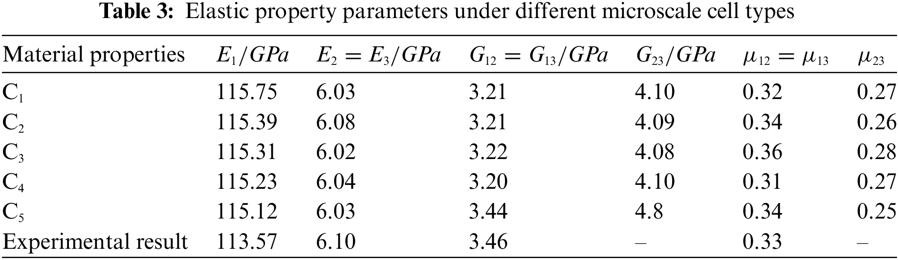
To corroborate the precision of the homogenization theory, which is predicated on thermal stress, in forecasting the elastic attributes of microscale cells, this research juxtaposes its derived outcomes with empirical evidence found in the literature [27], as depicted in Table 3. This juxtaposition reveals the maximum discrepancy lies within the Poisson’s ratio, manifesting a variance of 3.03%. Given the intrinsic uncertainties tied to experimental procedures, these results underscore the efficacy of the utilized method in precisely estimating the elastic characteristics of composite materials.
2.2.2 Influence of Microscale Parameters on Elastic Properties
Carbon fiber-reinforced composites are composed of a fiber reinforcement phase and a matrix resin, wherein the ratio of each component plays a crucial role in determining the composite’s overall performance. To investigate the influence of fiber volume fraction on the elastic properties of unidirectional CFRP, this study has examined the impact of various fiber volume fractions by conducting a series of analyses on microscale cells. These analyses employed the boundary force-based and thermal stress-based homogenization methods, as detailed in Section 2.1, with the results being presented in Fig. 5.
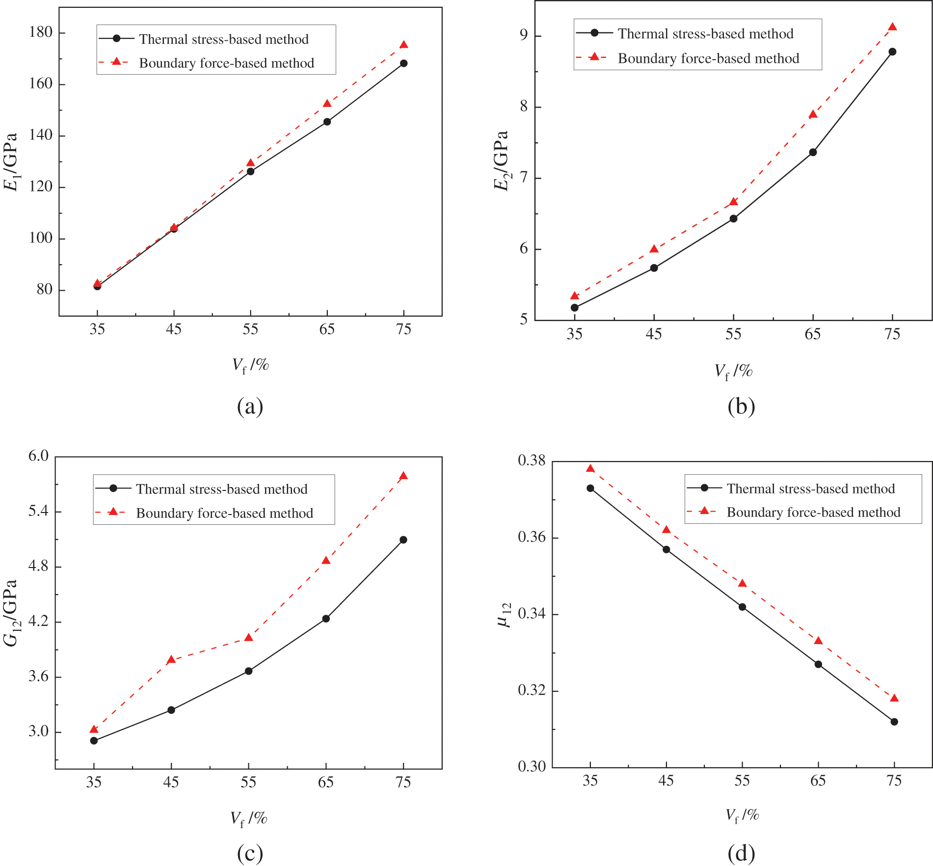
Figure 5: The influence of fiber volume fraction on the elastic properties of CFRP: (a) E1, (b) E2, (c) G12, (d) μ12
From Fig. 5, it is evident that the results yielded by both homogenization analysis methods are essentially consistent. Specifically, as the fiber volume fraction (Vf) increases, the elastic modulus increases while the Poisson’s ratio decreases, implying that the overall performance of the composite material improves with an increased proportion of fibers. Noteworthy is the observation that with the increase in Vf, E1 shows a linear increasing trend, whereas E2 and G12 exhibit progressively higher rates of increase with rising Vf. This can be attributed to the fact that the elastic modulus of the fibers is significantly higher than that of the resin. During axial loading, the fibers primarily bear the load, at lower fiber proportions, the transverse properties of the composite material are mainly determined by the resin. However, as the fiber content increases, the influence of the fibers becomes more pronounced, hence the increasingly rapid increase in E2 and G12 with higher Vf. In summary, both homogenization analysis methods have been shown to accurately predicting the elastic properties of unidirectional CFRP. Considering the computational efficiency for subsequent reliability optimization, this paper has chosen the thermal stress-based homogenization method as the microscale analysis approach for further optimization.
2.2.3 Influence of Design Parameters Uncertainty on Elastic Properties
In practical engineering design, numerous uncertainties, such as variability in material parameters and fluctuations in characteristic dimensions, exist. These uncertainties can pose risks of failure to the outcomes of deterministic designs, as noted in references [18,22]. To address the effects of uncertainties on the elastic properties of composite materials, this section focuses on the study of microscale cells of composite materials, specifically examining the impact of uncertainties in design variables on their elastic properties.
In evaluating the influence of parameter fluctuations in microscale cells on the elastic properties of composite materials, the cells were designed with a fiber volume fraction (Vf) of 51%, yielding a calculated half-side length (x1) of 6.7392 mm. As indicated in [22], the characteristic dimensions of composite materials within tolerance ranges are generally assumed to follow a uniform distribution. For sizes lacking specific tolerance information, limit deviations are established based on standard tolerances for unspecified dimensions. Specifically, for characteristic sizes between 6 and 10 mm, the deviation range is set at ±0.18 mm. Using Python, 400 sets of half-side lengths ranging from 6.5592 to 6.9192 mm, conforming to a uniform distribution, were generated. These sets were then analyzed in batch using thermal stress-based homogenization theory, efficiently computing the varying elastic properties of the cells. The results of these analyses are illustrated in histograms, showcasing the distributions of the cells’ elastic moduli E1 and E2, as well as the Poisson’s ratio μ12.
An analysis of Fig. 6 reveals that when the side length of the microscale cell fluctuates during the design process and follows a uniform distribution, the longitudinal elastic modulus E1, transverse elastic modulus E2, and Poisson’s ratio μ12 of the composite material all approximately follow a uniform distribution. Further examination of the histograms indicates that due to the fluctuation in cell size, the homogenized longitudinal elastic modulus E1 varies within the range of [111000, 124000 MPa], the transverse elastic modulus E2 fluctuates between [5936, 6356 MPa], and the Poisson’s ratio μ12 fluctuates within [0.3483, 0.3523]. The range of fluctuation for the elastic modulus E1 is the largest, reaching 11.72%. In summary, fluctuations in characteristic dimensions significantly impact the elastic properties of composite materials, and this influence should be fully considered in the design process.

Figure 6: The influence of microscale cell size variation on elastic properties: (a) E1, (b) E2, (c) μ12
To investigate the impact of fluctuations in the properties of component materials on the elastic properties of composite materials, literature [21] indicates that the elastic modulus of carbon fibers typically follows a normal distribution. In this study, the elastic modulus of carbon fibers was assumed to follow a normal distribution with a mean of 227 GPa and a standard deviation of 4.32. In Python, 400 sets of data conforming this distribution were generated to solve for the elastic properties of composite materials under the fluctuation of carbon fiber modulus. These computational results were subsequently processed, and histograms were drawn to illustrate the distribution of the microscale cell’s elastic modulus E1, shear modulus E2, and Poisson’s ratio μ12.
From Fig. 7, it is evident that during the design process, when the modulus of carbon fibers fluctuates and conforms to a normal distribution, the homogenized elastic modulus E1 of the microscale cell approximately follows a normal distribution with a mean of 117139 MPa and a standard deviation of 2.24. Similarly, the elastic modulus E2 approximates a normal distribution with a mean of 6132 MPa and a standard deviation of 0.00058, while the Poisson’s ratio μ12 is distributed with a mean of 0.3483 and a standard deviation of 0.0000275. Further observation of the histograms shows that due to the fluctuation in the material parameters of the cell, the homogenized longitudinal elastic modulus E1 varies within the range of [117132, 117146 MPa], with a maximum fluctuation of only 14 MPa. The fluctuation ranges for transverse elastic modulus E2 and Poisson’s ratio μ12 are extremely small. Given that the fluctuation in modulus has a comparatively minor effect on the elastic properties of composite materials, the uncertainty in the properties of component materials is not considered significant in the subsequent optimization process discussed in this paper.

Figure 7: The influence of fiber filament modulus variation on elastic properties: (a) E1, (b) E2, (c) μ12
3 Carbon Fiber-Reinforced Composite Drive Shafts
3.1 Carbon Fiber-Reinforced Composite Drive Shafts and Performance Indicators
This paper focuses on the CFRP drive shaft, which has been experimentally validated as per literature [10]. Fig. 8 presents the schematic diagrams of the CFRP drive shaft sample and its loading conditions. The drive shaft is characterized by a tube length of 1040 mm, a diameter of 70 mm, and a wall thickness of 3 mm, and is designed to withstand a maximum torque of 1120
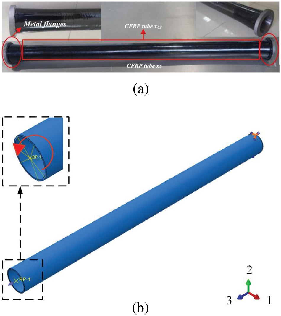
Figure 8: Schematic view of a CFRP Drive Shaft Structure: (a) CFRP drive shaft, (b) Drive shaft torsional loading case
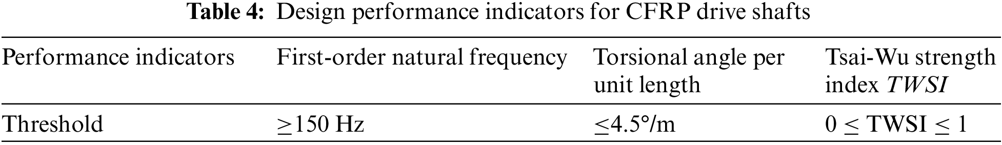
During the design process of the drive shaft, a crucial transmission component in automobiles, meeting the torsional stiffness requirements is imperative. Additionally, in operation, the high-speed rotation of the drive shaft can induce vibrations, potentially leading to resonance. The occurrence of resonance not only compromises the vehicle’s overall stability but also shortens the lifespan of the drive shaft. Consequently, in the design of CFRP drive shafts, it is critical to ensure that both the torsional stiffness and the initial natural frequency satisfy the design specifications while also pursuing a lightweight design. The performance indicators for the CFRP drive shaft are listed in Table 4, as referenced in [9,10].
3.2 Influence of Microscale Design Parameters on Drive Shaft Performance
To explore the influence of fiber volume fraction on the performance of CFRP drive shafts, the comprehensive performance of the drive shaft was calculated by varying the half-side length x1 of the microscale cell for different fiber volume fractions. In ABAQUS, a 10-layer laminate with a single layer thickness of 0.3 mm was constructed, with the layup angles fixed at [0°, 45°, 90°, −45°, 0°, 45°, 90°, 0°, 45°, 90°]. By adjusting the size of the microscale cell’s design variable x1, as shown in Fig. 1, fiber volume fractions ranging from 35% to 75%, with increments of 5%, were used for torsional stiffness and modal analysis. Fig. 9 illustrates the relationship between the torsional stiffness, mass, and initial natural frequency of the drive shaft and the fiber volume fraction.

Figure 9: Influence of fiber volume fraction on drive shaft performances
Analysis of Fig. 9 reveals that with an increase in the fiber volume fraction, there was a corresponding gradual increase in the torsional stiffness of the drive shaft, indicated by a decrease in the torsional angle per unit length. Concurrently, the mass of the drive shaft rose as the fiber volume fraction increased, attributable to the higher density of fibers relative to resin. Additionally, a rise in the fiber volume fraction led to an increase in the initial natural frequency. In summary, the fiber volume fraction has had a considerable impact on the performance of the drive shaft. While the drive shaft’s performance enhances with an increased fiber volume fraction, there is a concomitant decline in its lightweight performance.
3.3 Influence of Macroscale Design Parameters on Drive Shaft Performance
To investigate the relationship between the layup angles in composite materials and drive shaft performances, a unidirectional fiber composite material with 51% fiber volume fraction was selected for analysis using the aforementioned finite element model. Layup angles for individual layers were set at 5° intervals within the range of [0°, 90°], and simulations were conducted using a 10-layer laminate with uniform layup angles. Fig. 10 depicts the correlation between the torsional stiffness, initial natural frequency, and the layup angles of the drive shaft.

Figure 10: Influence of layup angles on drive shaft performances
An analysis of Fig. 10 reveals that the layup winding angle significantly influenced the torsional stiffness of the drive shaft. With an increase in the layup winding angle, the drive shaft’s torsional stiffness showed an initial increase followed by a decrease, peaking at a layup angle of 45°. Consequently, to ensure the torsional stiffness met the design requirements, it was advisable to increase the proportion of the 45° layup in the design. Furthermore, the initial natural frequency of the drive shaft generally exhibited a downward trend as the layup winding angle increased. Beyond a layup angle of 50°, this decline stabilized, and further increases in the layup angle resulted in a slight rise in the initial natural frequency. To maintain the natural frequency within the desired design specifications, increasing the proportion of lower-angle layups was recommended during the integrated design process.
4 Multiscale Reliability-Based Design Optimization Method
4.1 Definition of the Optimization Model
To enhance the torsional stiffness of the drive shaft while achieving maximum lightweighting, this study set the mass M and torsional angle TA of the CFRP drive shaft as the objectives, with the initial natural frequency f, the Tsai-Wu strength index (TWSI) [29], and the specifications for the layup process as constraints. Consequently, we developed the following optimization mathematical model:
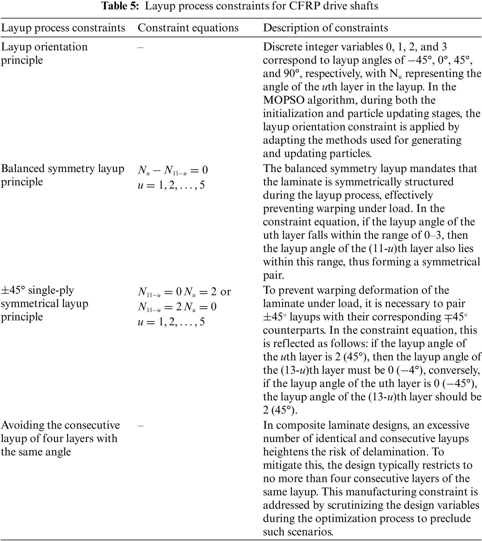
where variable x1 denotes the half-side length of the microscale cell, with a value range of [5.5, 8], while x2 to x11 are discrete layup angles (as shown in Fig. 1), each allowing a choice among four layup angles: −45°, 0°, 45°, and 90°. To ensure that the obtained optimization results meet the layup process constraints of composite materials, this paper integrated these constraints into the multi-objective particle swarm optimization algorithm (MOPSO) [30], with the specific implementation methods shown in Table 5 [31].
Based on the deterministic optimization model previously established, this study additionally developed a multiscale reliability optimization design mathematical model for the CFRP drive shaft, explicitly incorporating the uncertainties in microscale cell parameters and layup angles, as described below:
where design feasibility is defined as the probability (p[•])) that the satisfaction of constraints is greater than or equal to a predetermined desired probability level [4,5,32]. Specifically, p1 and p2 denote the probabilities of satisfying the constraints on the initial natural frequency and torsional angle, respectively. The reliability requirements for these constraints, R1 and R2, were set at different levels of 90%, 95%, and 99% in this study. Furthermore, x1 is assumed to follow a uniform distribution, while the layup angles xi follow a normal distribution [22].
4.2 Multiscale Reliability-Based Design Optimization Method
Based on the unidirectional CFRP multiscale analysis method introduced in Section 2 and the macroscopic performance analysis method for CFRP drive shafts detailed in Section 3, this study has developed a multiscale reliability design approach for CFRP drive shafts, as depicted in Fig. 11. The principal steps of this approach include:

Figure 11: Flow chart of the multiscale reliability-based design optimization method
Step 1: Improving the particle generation and updating strategy of MOPSO to consider the layup process constraints of carbon fiber-reinforced composites: In the MOPSO algorithm, the layup orientation constraint, along with process constraints such as the balanced symmetry layup principle, the ±45° single-ply symmetrical layup principle, and avoiding the consecutive layup of four layers with the same angle, have been effectively integrated and applied through adapted methods for generating and updating particles.
Step 2: CFRP multiscale modeling and elastic parameters prediction: Python programming was utilized for the parametric modeling of microscale cells. Furthermore, the homogenization theory based on thermal stress was applied to accurately predict the cells’ elastic properties.
Step 3: Construction and parameter transfer of the CFRP drive shaft model: Using ABAQUS software, a CFRP drive shaft model was developed, which incorporated material parameters predicted in step 2. Subsequent analyses, including torsional stiffness and modal analyses, were conducted on this drive shaft model to assess its performance. Following these analyses, a parametric model of the CFRP drive shaft was established, leading to the development of a multiscale reliability optimization model.
Step 4: Development of a multiscale reliability-based design optimization method for CFRP drive shaft: An innovative multiscale reliability optimization algorithm for the design and analysis of CFRP drive shafts was proposed, integrating the enhanced multi-objective particle swarm algorithm with both micro and macro-analysis techniques for CFRP drive shafts.
4.3.1 Deterministic Optimization Results
In this study, the efficacy of the modified MOPSO algorithm in handling layup process constraints for CFRP drive shafts was assessed through simulations spanning 60, 80, 100, and 120 generations. Stability in convergence was observed at the 100-generation mark. The parameters of the modified MOPSO algorithm are detailed in Table 6. We applied the algorithm to address the optimization problem outlined in Eq. (5), examining scenarios both with and without these constraints. The resulting Pareto solution sets are illustrated in Fig. 12. A critical observation is the inherent conflict between torsional stiffness and mass in the CFRP drive shaft, indicating that a solution from the Pareto set with increased torsional stiffness usually corresponds to a higher shaft mass, and vice versa. Remarkably, when layup constraints are factored in, the solution sets show significant variation in distribution, with the constrained set occupying the upper right quadrant relative to the unconstrained set. This shift can be attributed to the limited design space due to layup constraints, which excludes some solutions that offer lower mass yet higher stiffness. An analysis of the layup angles in the solution sets reveals that all solutions in the set considering constraints adhere to the stipulations detailed in Table 5, unlike the unconstrained set. In summary, the enhanced MOPSO algorithm adeptly handles layup constraints in composite materials. While the resultant optimal solutions may entail some performance trade-offs, they consistently align with process constraints, effectively circumventing the risks of unfeasible layup designs.
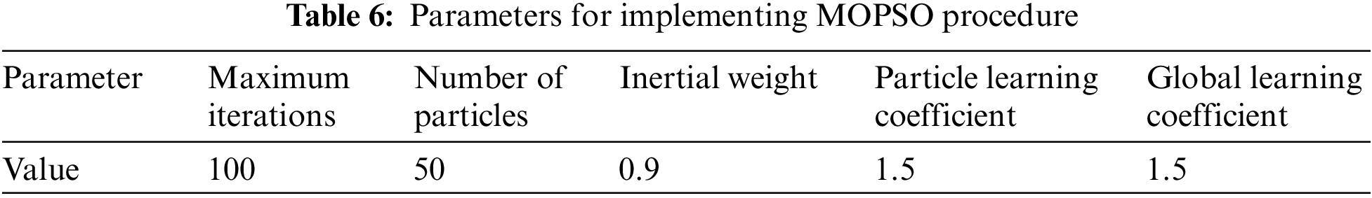

Figure 12: Pareto solutions for deterministic optimization
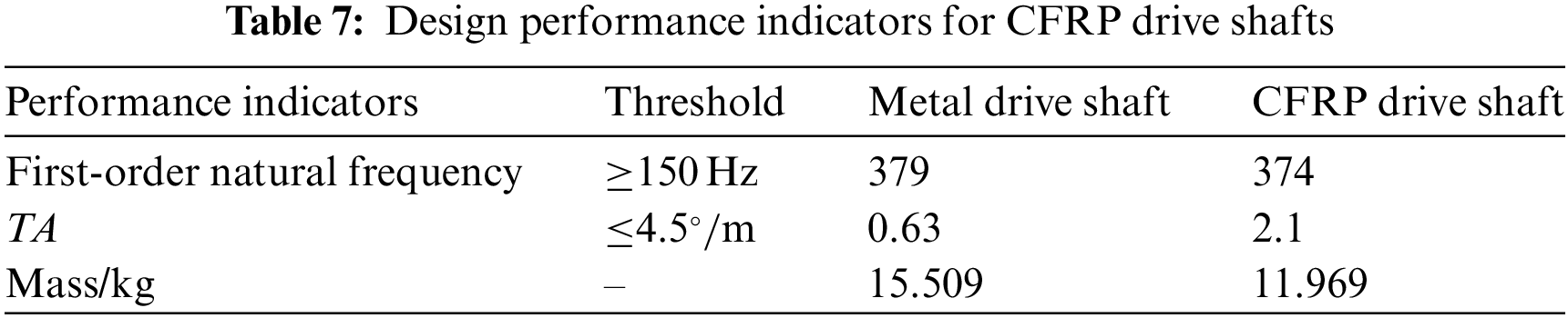
While the Pareto solution set presents numerous feasible options, selecting a suitable solution that guides engineering design is pivotal in practical scenarios. To effectively balance the conflicting performance indicators of torsional stiffness and mass in the CFRP drive shaft, this study adopts the minimum distance selection method [17], identifying optimal solutions from the sets shown in Fig. 12. The optimal solution under layup process constraints is identified as: a fiber volume fraction of 68.4%, with a layup configuration of [45°, 0°, 90°, 0°, −45°, 45°, 0°, 90°, 0°, −45°]. A comparative analysis, as detailed in Table 7, between composite material drive shafts under these optimal solutions and traditional metallic drive shafts reveals a significant finding: the unidirectional CFRP drive shaft, inclusive of the metal flanges at both ends of the shaft tube, achieves a weight reduction of 22.8%, while meeting both stiffness and modal design criteria, thus underscoring a substantial lightweighting advantage. To estimate the reliability of probabilistic constraints, this section employs the Monte Carlo simulation (MCS) method to assess the reliability of the initial natural frequency constraint [17]. A brief overview of the MCS is presented in the Appendix A. While the accuracy of these estimates is directly correlated with the number of Monte Carlo simulations. To determine an appropriate number of simulations, this paper conducted MCS with 40, 60, 80, and 100 samples, respectively. It was found that the reliability of probabilistic constraints converged when 100 MCS iterations were performed. Therefore, all reliability assessments within this study utilized 100 Monte Carlo simulations. The distribution of design variables is presented as shown in Eq. (6). The analysis reveals that the reliability of the optimal solution here is only 71.2%. When considering the uncertainty of design parameters, this optimal solution poses a significant risk of failure.
4.3.2 Reliability-Based Optimization Results
The mathematical model described in Eq. (6) was solved using the multiscale reliability design method for carbon fiber-reinforced composite structures proposed in this paper. Fig. 13 presents the solution sets for deterministic and reliability design of unidirectional fiber composite drive shafts. From the figure, it is evident that in the reliability optimization design of composite material drive shafts, the mass and torsional stiffness are conflicting parameters, and improving the lightweighting effect inevitably leads to a reduction in torsional stiffness. Additionally, comparing the optimal solution sets of deterministic and reliability designs, while their shapes are quite similar, there is a significant difference in their distribution and range. This indicates that the fluctuation of design variables greatly impacts the performance of the drive shaft. Specifically, the optimal solution set considering structural reliability deviates from the deterministic optimal solutions, with the reliability design solutions situated above and to the right of the deterministic solutions, and this deviation increases with the demand for higher reliability. The fundamental reason for this phenomenon is that as the reliability requirements for constraints increase, the feasible domain of design variables narrows, leading the higher reliability optimal solutions to move away from constraint boundaries, resulting in some sacrifice of performance.

Figure 13: Pareto solutions for reliability-based optimization
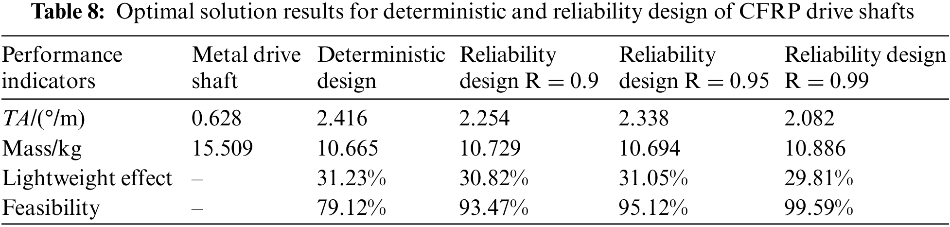
To further illustrate, the minimum distance selection method has been used to select the optimal solution from the Pareto set, as presented in Table 8. Data from the table indicates that both deterministic and reliability designs have enhanced the lightweight and torsional stiffness performance of the CFRP drive shaft. However, the comprehensive reliability for the constraints in the deterministic design only reached 79.12%. By contrast, the optimal solutions from the reliability design have met the predefined reliability requirements. Notably, the performance metrics for the reliability design are marginally lower than those for the deterministic design, suggesting that in practical engineering applications, a certain trade-off between reliability requirements and performance metrics is necessary.
In this study, a multiscale reliability-based design optimization methodology for carbon fiber-reinforced composites was developed, and demonstrated through a case study on a unidirectional CFRP drive shaft. The main conclusions are as follows:
(1) The boundary force-based and thermal stress-based homogenization methods were employed to predict the elastic properties of unidirectional CFRP. The findings suggest a general consistency in the predictions from both methods. Notably, compared to experimental data from the literature, the thermal stress-based homogenization method aligned more closely with experimental outcomes.
(2) Investigations into the influence of uncertainties in microscale cell parameters on the elastic properties of unidirectional CFRP revealed that the uncertainty in the half-side length of microscale cells, reflecting fiber volume content, has a more pronounced effect on these properties as compared to the variability in matrix material properties.
(3) The application of the refined MOPSO algorithm for the design optimization of unidirectional CFRP drive shafts has proven its efficacy in managing constraints including the balanced symmetry layup principle, the ±45° single-ply symmetrical layup principle, and the prevention of consecutive layups of four identical angles. This capability significantly enhances the engineering applicability of the multiscale optimization method proposed in this research.
(4) Applying the multiscale reliability-based design optimization methodology to a unidirectional CFRP drive shaft, the results indicate that the optimal solutions not only enhance the comprehensive performance of the drive shaft but also meet the reliability requirements of the constraints as per the design specifications.
Acknowledgement: We would like to thank the authors for their contributions to this manuscript. We also thank the journal of CMES for their supports for publications of this special issue.
Funding Statement: This research work was supported by the S&T Special Program of Huzhou (Grant No. 2023GZ09) and the Open Fund Project of the Shanghai Key Laboratory of Lightweight Structural Composites (Grant No. 2232021A4-06).
Author Contributions: The authors confirm contribution to the paper as follows: study conception and design: Huile Zhang, Yurui Wu, data collection: Shikang Li, Huile Zhang, Pengpeng Zhi, analysis and interpretation of results: Huile Zhang, Wei Wang, Zhonglai Wang, draft manuscript preparation: Huile Zhang. All authors reviewed the results and approved the final version of the manuscript.
Availability of Data and Materials: Not applicable.
Conflicts of Interest: The authors declare that they have no conflicts of interest to report regarding the present study.
References
1. Wazeer A, Das A, Abeykoon C, Sinha A, Karmakar A. Composites for electric vehicles and automotive sector: a review. Green Energy Intell Transp. 2023;2(1):100043. doi:10.1016/j.geits.2022.100043. [Google Scholar] [CrossRef]
2. Singh T, Singh V, Ranakoti L, Kumar S. Optimization on tribological properties of natural fiber-reinforced brake friction composite materials: effect of objective and subjective weighting methods. Polym Test. 2023;117:107873. doi:10.1016/j.polymertesting.2022.107873. [Google Scholar] [CrossRef]
3. Petcharat N, Wiangkham A, Pichitkul A, Tantrairatn S, Aengchuan P, Bureerat S, et al. The multi-objective optimization of material properties of 3D print onyx/carbon fiber composites via surrogate model. Mater Today Commun. 2023;37:107362. doi:10.1016/j.mtcomm.2023.107362. [Google Scholar] [CrossRef]
4. Wang X, Meng Z, Yang B, Cheng C, Long K, Li J. Reliability-based design optimization of material orientation and structural topology of fiber-reinforced composite structures under load uncertainty. Compos Struct. 2022;291:115537. doi:10.1016/j.compstruct.2022.115537. [Google Scholar] [CrossRef]
5. Hao P, Yang H, Wang Y, Liu X, Wang B, Li G. Efficient reliability-based design optimization of composite structures via isogeometric analysis. Reliab Eng Syst Saf. 2021;209:107465. doi:10.1016/j.ress.2021.107465. [Google Scholar] [CrossRef]
6. Bambach MR. Fibre composite strengthening of thin steel passenger vehicle roof structures. Thin-Walled Struct. 2014;74:1–11. doi:10.1016/j.tws.2013.09.018. [Google Scholar] [CrossRef]
7. Lee JM, Lee KH, Kim BM, Ko DC. Design of roof panel with required bending stiffness using CFRP laminates. Int J Precis Eng Manuf. 2016;17(4):479–85. doi:10.1007/s12541-016-0060-6. [Google Scholar] [CrossRef]
8. Liu Q, Lu Y, Jiang J, Yan X, Li Q. Experimental and numerical investigation into the dynamic impact responses of CFRP header rail. Thin-Walled Struct. 2022;181:110069. doi:10.1016/j.tws.2022.110069. [Google Scholar] [CrossRef]
9. Abu Talib AR, Ali A, Badie MA, Azida Che Lah N, Golestaneh AF. Developing a hybrid, carbon/glass fiber-reinforced, epoxy composite automotive drive shaft. Mater Des. 2010;31(1):514–21. doi:10.1016/j.matdes.2009.06.015. [Google Scholar] [CrossRef]
10. Sun Z, Xiao J, Yu X, Tusiime R, Gao H, Min W, et al. Vibration characteristics of carbon-fiber-reinforced composite drive shafts fabricated using filament winding technology. Compos Struct. 2020;241:111725. doi:10.1016/j.compstruct.2019.111725. [Google Scholar] [CrossRef]
11. Soliman ESMM. Optimization of ply-laminated stacking sequence for composite drive shaft. J Fail Anal Prev. 2023;23(1):176–90. doi:10.1007/s11668-022-01562-y. [Google Scholar] [CrossRef]
12. Hasan KMF, Horváth PG, Alpár T. Potential fabric-reinforced composites: a comprehensive review. J Mater Sci. 2021;56(26):14381–415. doi:10.1007/s10853-021-06177-6. [Google Scholar] [CrossRef]
13. David Müzel S, Bonhin EP, Guimarães NM, Guidi ES. Application of the finite element method in the analysis of composite materials: a review. Polym. 2020;12(4):818. doi:10.3390/polym12040818. [Google Scholar] [PubMed] [CrossRef]
14. Liu Q, Lin Y, Zong Z, Sun G, Li Q. Lightweight design of carbon twill weave fabric composite body structure for electric vehicle. Compos Struct. 2013;97(Supplement C):231–8. [Google Scholar]
15. Cheng F, Zheng C, Liu Y, Zuo W, Wang X, Guo G. Lightweight design of CFRP-laminated structures by combining microscopical homogenization and macroscopical optimization. Int J Automot Technol. 2021;22(5):1427–36. doi:10.1007/s12239-021-0124-1. [Google Scholar] [CrossRef]
16. Fang G, Qu P, Cao Z, Shi F. Mechanical analysis of woven composites through experimental investigation and multiscale numerical simulation. Fibers Polym. 2022;23(5):1440–53. doi:10.1007/s12221-022-4061-z. [Google Scholar] [CrossRef]
17. Sun G, Zhang H, Fang J, Li G, Li Q. Multi-objective and multi-case reliability-based design optimization for tailor rolled blank (TRB) structures. Struct Multidiscip Optim. 2017;55(5):1899–916. [Google Scholar]
18. Zhang LX, Meng XJ, Ding ZJ, Han HX. Simulation-based reliability design optimization method for industrial robot structural design. Appl Sci. 2023;13(6):3776. doi:10.3390/app13063776. [Google Scholar] [CrossRef]
19. Zhou XY, Gosling PD, Ullah Z, Kaczmarczyk Ł, Pearce CJ. Exploiting the benefits of multi-scale analysis in reliability analysis for composite structures. Compos Struct. 2016;155:197–212. doi:10.1016/j.compstruct.2016.08.015. [Google Scholar] [CrossRef]
20. Liu Z, Zhu C, Zhu P, Chen W. Reliability-based design optimization of composite battery box based on modified particle swarm optimization algorithm. Compos Struct. 2018;204(15):239–55. [Google Scholar]
21. Omairey SL, Dunning PD, Sriramula S. Multiscale surrogate-based framework for reliability analysis of unidirectional FRP composites. Compos Part B: Eng. 2019;173(15):106925. [Google Scholar]
22. Sun T, Jiang R, Sun H, Liu D, Pan Z. Multiscale uncertainty propagation analysis and reliability optimization of the CFRP crossbeam of the twist beam axle. Int J Mech Sci. 2023;242(15):108022. [Google Scholar]
23. Ng SP, Tse PC, Lau KJ. Numerical and experimental determination of in-plane elastic properties of 2/2 twill weave fabric composites. Compos Part B: Eng. 1998;29(6):735–44. doi:10.1016/S1359-8368(98)00025-0. [Google Scholar] [CrossRef]
24. Wu W, Liu Q, Lin YZ, Zong Z. Investigation on rapid prediction of elastic properties for woven fabric composites. Adv Mater Res. 2012;535–537:247–52. [Google Scholar]
25. Yuan Z, Fish J. Toward realization of computational homogenization in practice. Int J Numer Methods Eng. 2008;73(3):361–80. doi:10.1002/nme.v73:3. [Google Scholar] [CrossRef]
26. Tang SF, Huang FH, Liang J, Du SY. Multi-scale analysis for thermo-elasticity properties of composite materials with small periodic configuration. Key Eng Mater. 2007;334–335:25–8. [Google Scholar]
27. Hong J. Integrated design of structure and material of carbon fiber-reinforced plastics (CFRP) (Master of Engineering). Hunan University: China; 2018. [Google Scholar]
28. Zhang H, Sun Z, Zhi P, Wang W, Wang Z. Material-structure integrated design and optimization of a carbon-fiber-reinforced composite car door. Appl Sci. 2024;14(2):930. doi:10.3390/app14020930. [Google Scholar] [CrossRef]
29. Tsai SW, Wu EM. A general theory of strength for anisotropic materials. J Compos Mater. 1971;5(1):58–80. doi:10.1177/002199837100500106. [Google Scholar] [CrossRef]
30. Coello CAC, Lechuga MS. MOPSO: a proposal for multiple objective particle swarm optimization. In: Proceedings of the 2002 Congress on Evolutionary Computation. CEC’02 (Cat. No. 02TH86002002 May 12–17; Honolulu, USA. [Google Scholar]
31. Duan Z, Jung Y, Yan J, Lee I. Reliability-based multi-scale design optimization of composite frames considering structural compliance and manufacturing constraints. Struct Multidiscip Optim. 2020;61(6):2401–21 doi:10.1007/s00158-020-02517-3. [Google Scholar] [CrossRef]
32. Ye B, Yu G, Zhang Y, Li G. Structural design of aerostatic bearing based on multi-objective particle swarm optimization algorithm. Appl Sci. 2023;13(5):3355. doi:10.3390/app13053355. [Google Scholar] [CrossRef]
33. Lemaire M. Structural reliability. NJ: John Wiley & Sons; 2013. [Google Scholar]
Appendix A: Estimating the Probability of Failure Using Monte Carlo Simulations
Monte Carlo Simulation (MCS) is a numerical method used to estimate the probability of complex events by simulating random processes. In the context of reliability engineering, MCS is applied to estimate the probability of failure, defined as
The probability of failure is estimated as follows:
where N is the total number of Monte Carlo simulations, I is the indicator function, equal to 1 if
Cite This Article
 Copyright © 2024 The Author(s). Published by Tech Science Press.
This work is licensed under a Creative Commons Attribution 4.0 International License , which permits unrestricted use, distribution, and reproduction in any medium, provided the original work is properly cited.
 Downloads
 Citation Tools