 Open Access
ARTICLE
Design and Performance Analysis of HMDV Dynamic Inertial Suspension Based on Active Disturbance Rejection Control
1 School of Automotive and Traffic Engineering, Jiangsu University, Zhenjiang, 212013, China
2 Automotive Engineering Research Institute, Jiangsu University, Zhenjiang, 212013, China
3 Chongqing Key Laboratory of Urban Rail Transit System Integration and Control, Chongqing, 400074, China
4 State Key Laboratory of Advanced Design and Manufacturing Technology for Vehicle, Hunan university, Changsha, 410082, China
* Corresponding Author: Wei Wang. Email:
Computer Modeling in Engineering & Sciences 2024, 140(2), 1485-1506. https://doi.org/10.32604/cmes.2024.049837
Received 19 January 2024; Accepted 09 April 2024; Issue published 20 May 2024
Abstract
This paper addresses the impact of vertical vibration negative effects, unbalanced radial forces generated by the static eccentricity of the hub motor, and road excitation on the suspension performance of Hub Motor Driven Vehicle (HMDV). A dynamic inertial suspension based on Active Disturbance Rejection Control (ADRC) is proposed, combining the vertical dynamic characteristics of dynamic inertial suspension with the features of ADRC, which distinguishes between internal and external disturbances and arranges the transition process. Firstly, a simulation model of the static eccentricity of the hub motor is established to simulate the unbalanced radial electromagnetic force generated under static eccentricity. A quarter-vehicle model of an HMDV with a controllable dynamic inertial suspension is then constructed. Subsequently, the passive suspension model is studied under different grades of road excitation, and the impact mechanism of suspension performance at speeds of 0–20 m/s is analyzed. Next, the three main components within the ADRC controller are designed for the second-order controlled system, and optimization algorithms are used to optimize its internal parameters. Finally, the performance of the traditional passive suspension, the PID-based controllable dynamic inertial suspension, and the ADRC-based controllable dynamic inertial suspension are analyzed under different road inputs. Simulation results show that, under sinusoidal road input, the ADRC-based controllable dynamic inertial suspension exhibits a 52.3% reduction in the low-frequency resonance peak in the vehicle body acceleration gain diagram compared to the traditional passive suspension, with significant performance optimization in the high-frequency range. Under random road input, the ADRC-based controllable dynamic inertial suspension achieves a 29.53% reduction in the root mean square value of vehicle body acceleration and a 14.87% reduction in dynamic tire load. This indicates that the designed controllable dynamic inertial suspension possesses excellent vibration isolation performance.Graphic Abstract

Keywords
Against the backdrop of rapid advancements in science and technology, coupled with the global shift towards carbon neutrality, countries worldwide are implementing corresponding policies and measures to promote the upgrading of production technologies and the development of new energy devices. Among various modes of transportation, automobiles, as indispensable means of daily commuting, are drawing special attention in terms of research and development. As a substitute for traditional fuel-driven vehicles, new energy vehicles integrate more sophisticated and precise high-end technologies, reduce energy consumption, and significantly enhance passenger comfort. Hub Motor Driven Vehicle, as a representative of distributed drive electric vehicles [1], stands out as an ideal configuration for future electric vehicles. This paper explores the cutting-edge developments in the design and research of automobiles, with a particular focus on HMDVs, and their potential to address the challenges posed by the evolving landscape of energy and environmental sustainability.
As a primary component of an automobile’s chassis architecture, the suspension system significantly influences various aspects of a vehicle, including performance, comfort, maneuverability, and safety. Existing suspension systems are broadly categorized into passive suspension [2,3], semi-active suspension [4], and active suspension [5,6]. The continuous improvement of suspension system performance stands as a key research direction in mitigating the adverse effects of vertical vibration in hub motor-driven vehicles. However, challenges such as inherent structural constraints and difficulties in overall performance enhancement through traditional suspension systems have impeded further development. In 2002, Smith et al. [7] proposed dynamic inertial suspension [8]. Dynamic inertial suspension, characterized by remarkable vertical dynamic behavior, emerges as a promising solution to address these challenges. Its application to the optimization of vertical dynamics and inerter adjustments in HMDVs can fully exploit its characteristics. This paper explores the state-of-the-art developments in suspension systems, emphasizing the utilization of dynamic inertial suspension to optimize the vertical dynamics and inerter adjustments in HMDVs, contributing to the effective suppression of vertical vibration associated with hub motor-driven vehicles.
Researchers both domestically and internationally have conducted in-depth investigations into dynamic inertial suspension, exploring various angles and application scenarios. Ma et al. [9] from Curtin University, summarizing studies over the past five years on the development and application of inerter-based control systems, concluded that the introduction of inerter components significantly enhances the isolation performance of systems. Baduidana et al. [10], employing H∞ and H2 optimization algorithms, investigated the isolation performance of series-parallel and series-connected dynamic inertial suspensions, providing theoretical foundations for the design of optimal inerter in future engineering practices. Shen et al. [11], incorporating fractional-order transfer functions into dynamic inertial suspension research, designed a Fractional Order Derivative Sliding Mode Controller (FD-SMC) and demonstrated its excellent isolation performance through experimental results. Alotta et al. [12] proposed an inerter-based device that, when connected to both ends of a diagonal of a rhombus, is activated by the movement along the other diagonal of the structural system, effectively reducing system vibrations. Currently, research on inerter in automotive suspension applications is a primary focus in dynamic inertial suspension studies. Simultaneously, extensive research has been conducted in fields such as construction [13], bridges [14], and trains [15], showcasing the superior isolation performance of dynamic inertial suspension.
In the 1980s, Chinese systems and control scientist Han [16,17] proposed the concept of Active Disturbance Rejection Control (ADRC). This control method combines the advantages of PID control with unique control strategies, demonstrating excellent control capabilities. Extensive research and discussions among scholars have highlighted the control advantages of ADRC across various domains. Wu et al. [18] conducts ADRC design research for high-order integral systems, summarizing the practical design process using a univariate method. Experimental results validate the advantages of ADRC in high-order integral systems. Guevara et al. [19], utilizing a two-stage disturbance observer with an active disturbance rejection control strategy, improved the backward trajectory tracking performance under non-ideal conditions and enhances overall closed-loop performance. Roman et al. [20] proposed a control strategy that combines active disturbance rejection control (ADRC) with sliding mode control (SMC), which can enhance the overall performance of the control system while ensuring its stability. Tian et al. [21], addressing the performance degradation in the current loop of a permanent magnet synchronous motor drive due to DC and AC components, proposed a current loop ADRC based on discrete-time repetitive control. Zhou et al. [22] introduced a novel controller that combines dynamic analysis and active disturbance rejection control strategy for a series-driven robotic system, providing high precision for assisting surgeons in vascular intervention robotic surgery. In conclusion, ADRC exhibits unique characteristics compared to other control strategies. Combining active disturbance rejection control with dynamic inertial suspension allows for the full exploitation of their performance advantages, suppressing the adverse effects of hub motor vertical vibration, unbalanced radial forces from static eccentricity, and road excitations on suspension performance.
This paper begins by establishing a static eccentricity model for hub motors, simulating the unbalanced radial electromagnetic forces generated by the motor. Building upon this foundation, a quarter-vehicle controllable dynamic inertial suspension model driven by a hub motor for automobiles is established. Subsequently, a model for random road inputs is constructed, studying the impact of different levels of random road excitations on suspension performance to determine the subsequent research focus on random road levels. Following this, the design of an active disturbance rejection control structure is introduced, employing particle swarm optimization algorithms to optimize controller parameters, thus determining the final structure and control parameters. Finally, under random and sinusoidal road inputs, the suspension performance of the traditional passive suspension, PID-based dynamic inertial suspension, and ADRC-based dynamic inertial suspension are analyzed.
2 Construction of Controllable Dynamic Inertial Suspension Model for HMDV
2.1 Static Eccentricity Model for Hub Motors
Hub motors, a crucial component in electric propulsion systems, are mainly categorized into different types, including Switched Reluctance Motor (SRM), Permanent Magnet Synchronous Motor (PMSM), Permanent Magnet Brushless DC Motor (PMBLDC), and Asynchronous Motor [23]. Due to its numerous advantages such as high torque at low speeds, strong controllability, and high reliability, the Switched Reluctance Motor is selected for the study of the hub motor eccentricity model. The chosen motor for investigation is an 8/6-pole four-phase external rotor SRM. Its basic structure is illustrated in Fig. 1, where the stator’s switching circuit is exemplified. This specific SRM configuration serves as the focal point for the development of the eccentricity model in hub motor research.
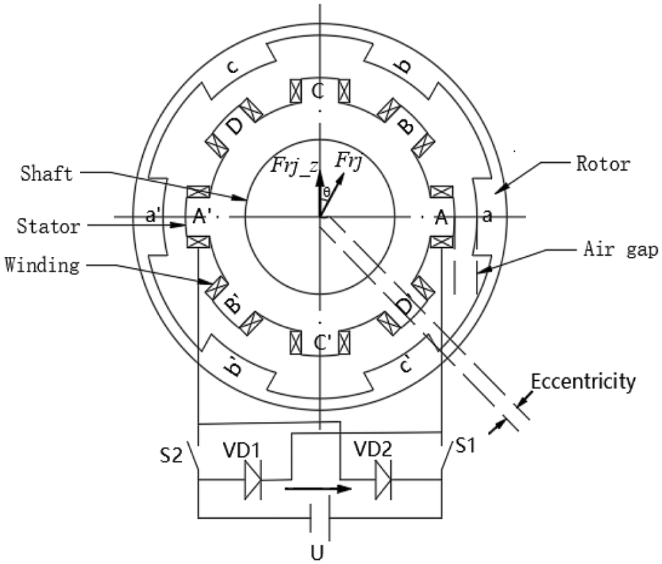
Figure 1: 8/6 pole four-phase switched reluctance motor
Before delving into the specific study of the eccentricity model, certain assumptions are made concerning the linear model of the motor [24]:
(1) The direct current voltage of the main circuit power supply remains constant.
(2) Semiconductor switches are ideal switches.
(3) Magnetic hysteresis, eddy current losses, and inter-winding mutual inductance are neglected.
(4) The speed remains constant within one current pulsation cycle.
In practical applications of Switched Reluctance Motors (SRMs), factors such as manufacturing variations, assembly processes, and wear can lead to misalignment between the stator and rotor, resulting in eccentricity, the static eccentricity of the motor is shown in Fig. 2. This eccentricity, in turn, affects the overall excitation of the motor in the vertical direction. This study focuses on a specific scenario where the minimum air gap position remains constant, and there is a vertical eccentricity. The objective is to investigate the influence of static eccentricity on the excitation of the switched reluctance motor under these specified conditions.
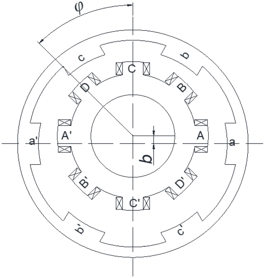
Figure 2: Motor static eccentricity diagram
Considering the period factor, reference [25] of the motor excitation and time of the single-phase rotor in the polyphase process is shown in Eqs. (1) and (2).
where L is the coil inductance, measured in Henries, H. θ is the rotor displacement angle, measured in radians, rad. Lmax is the maximum inductance. Lmin is the minimum inductance. θ0 is the critical contact overlap position between the stator and rotor. θ1 is the fully overlapped position. θ2 is the critical separation position between the stator and rotor. θ3 represents the fully separated position between the stator and rotor. K is the inductance rise slope, H/rad. δ is the range of action in a single-phase process, measured in radians, rad. Ns is the number of coil winding poles. b is the minimum gap between the rotor and stator, measured in meters, m. r is the outer radius of the stator, m. R is the inner radius of the rotor, m. TR is the single-phase rotor revolution period, measured in seconds, s.
At the initial moment, where each rotor’s initial position is denoted as θint, the displacement angle of each phase rotor at any given time can be expressed as θ = θint + ωt. The excitation force in the vertical direction received by the motor is shown in Eq. (3).
At a certain point, the vertical excitation generated by the motor as a whole is shown in Eq. (4).
For the convenience of subsequent calculation, it is assumed that the minimum gap between a pole winding and the rotor is located at the angle φ of the vertical axis. The smallest gap bn is shown in Eq. (5).
The basic parameters of the motor are shown in Table 1.

For eccentricities ranging from 0% to 10%, Fig. 3 illustrates the vertical forces generated by the motor. It can be observed that as the eccentricity gradually increases, the vertical excitation force produced by the motor also increases accordingly. Additionally, it is evident that the overall vertical excitation force of the motor exhibits periodic variations. During the relative interaction between the rotor and stator, the resulting radial force is decomposed into a vertically downward component, maintaining a consistently downward orientation for the overall vertical excitation force of the motor.
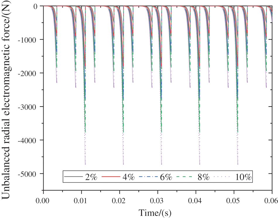
Figure 3: Unbalanced radial force of motor under eccentricity change
2.2 Quarter-HMDV Suspension Model
The controllable dynamic inertial suspension differs from traditional inerter suspension in that damping-elements are no longer incorporated into the suspension structure. Instead, a dual-component system comprising springs and electromechanical inerter containers is parallelly connected, and the output force generated by the rotary motor in the electromechanical inerter container is utilized for control effects. This configuration establishes a coupled vibration system of “sprung mass-inerter-unsprung mass”. The mechanism involves the interaction among the vehicle body, the controllable dynamic inertial suspension, the wheel-hub motor, and the road surface. A quarter-car controllable dynamic inertial suspension model for HMDV is developed, as illustrated in Fig. 4.
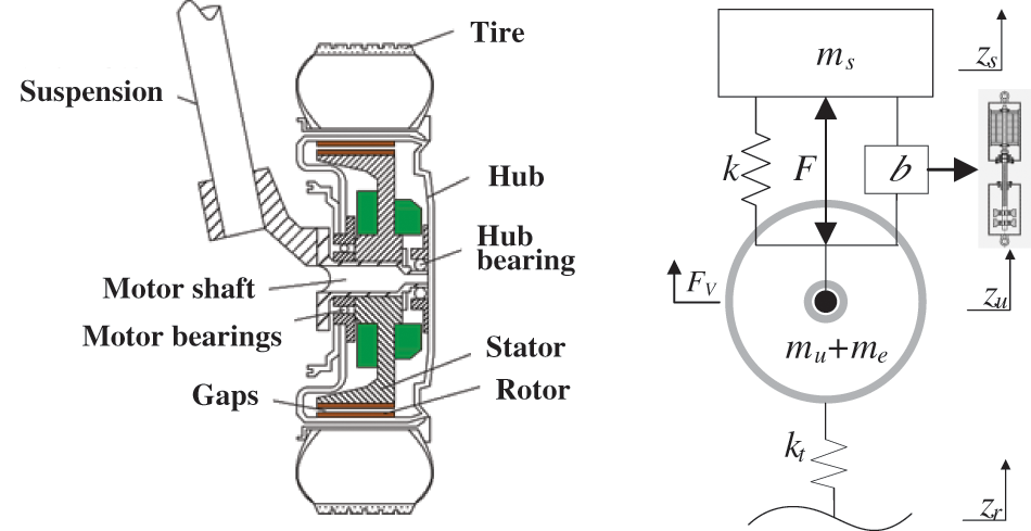
Figure 4: Quarter HMDV controllable dynamic inertial suspension model
Its dynamic equation is shown in Eq. (6).
where F is the output force generated by the rotating motor of the electromechanical inerter vessel, N; FV is the unbalanced radial electromagnetic force, N; ms is sprung mass, kg; mu + me is unsprung mass, kg; k and kt respectively represent the stiffness of the suspension spring and the tire spring, N/m; b is inerter coefficient, kg; zs, zu and zr represent the vertical displacements of the vehicle body, tire, and uneven road surface, respectively, m.
To further enhance control efficiency, the suspension model incorporates the velocity and displacement of both sprung and unsprung masses, along with road surface white noise input, as the input vector. The three-performance metrics of the suspension system (body acceleration, suspension working space, and dynamic tire load) are considered as the output vector. Consequently, the input vector and output vector can be obtained as shown in Eqs. (7) and (8).
Thus, its state space expression is shown in Eq. (9).
where each coefficient matrix is:
among
3 Influence Mechanism of Road Excitation on Suspension Performance
3.1 Construction of Random Pavement Input Model
Random road surfaces are classified into different levels based on their roughness. To thoroughly investigate the impact of hub motor vertical vibration negative effects on suspension performance, a simulation analysis will be conducted on traditional passive suspensions under various grades of random road surfaces.
The document ISO/TC 108/SC2N67, proposed by the International Organization for Standardization, obtained the expression of road power spectral density as shown in Eq. (10).
where Gq(n0) is the road roughness coefficient; n0 is the reference spatial frequency; n is the spatial frequency; W is the frequency index, and the approximate value is generally 2.
Pavement grades can be divided into 8 grades, as shown in Table 2.

The random pavement input model expression [26] is shown in Eq. (11).
where τ is the constant related to the grade of pavement, and its value is 0.111; zr(t) is the vertical displacement of road surface; v is the driving speed; ζ is the undetermined coefficient, both of which are 4.44; p0(t) represents white noise with a mean of zero.
3.2 Analysis of Influence Mechanism of Different Grade Pavement
Focusing on the impact of random road surface excitations of different levels on the suspension performance of HMDV, a comprehensive study is conducted using a quarter-vehicle hub motor-driven vehicle with a traditional passive suspension system as the main subject. The quarter-vehicle suspension configuration is illustrated in Fig. 5.
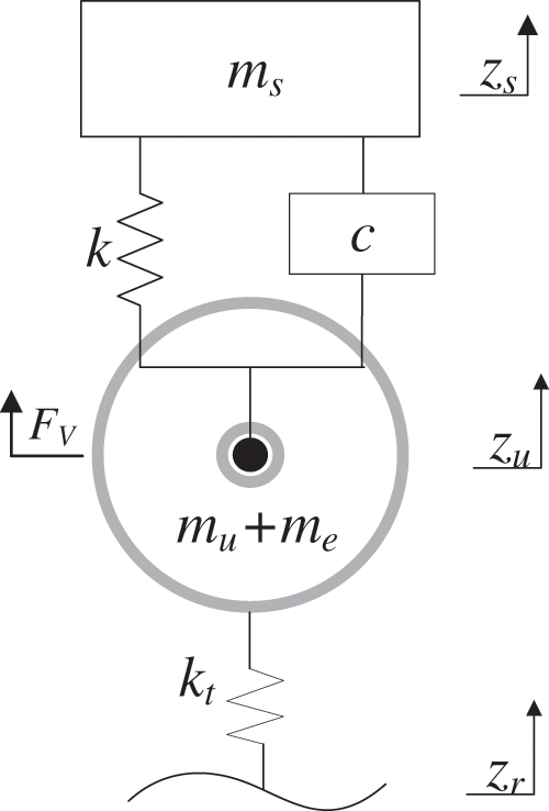
Figure 5: Quarter HMDV traditional passive suspension model
Its dynamic equation is shown in Eq. (12).
The structural parameters of a quarter HMDV suspension are shown in Table 3.

By utilizing the established quarter-HMDV suspension model with a static eccentricity set at 15%, the vehicle speed is incrementally varied from 0 to 20 m/s under different grades of road surfaces. Using the root mean square values of body acceleration, suspension working space, and dynamic tire load as comparative metrics for suspension performance, the analysis explores the impact mechanisms of hub motor vertical vibration negative effects under different road grades and speeds. Through data analysis of simulation results, the variations in body acceleration, suspension working space, and dynamic tire load are presented in Figs. 6–8.
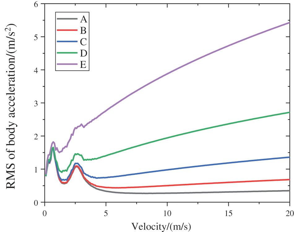
Figure 6: RMS of body acceleration at different speeds
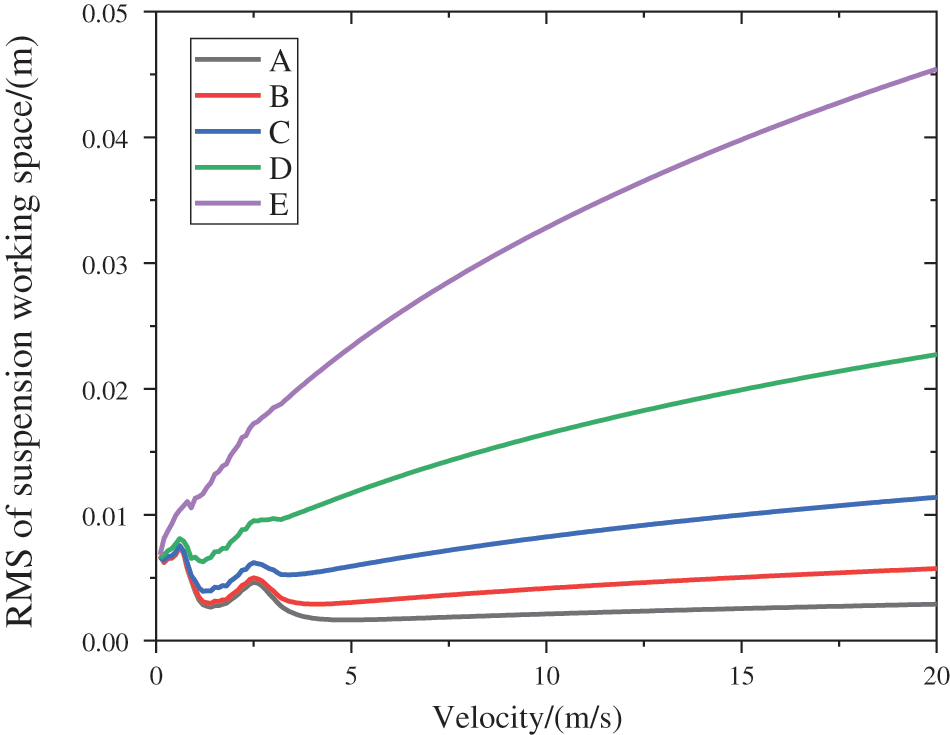
Figure 7: RMS of suspension working space at different speeds
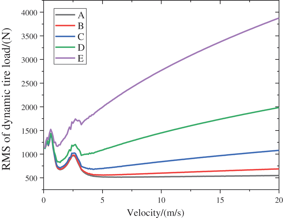
Figure 8: RMS of tire dynamic load at different speeds
From Fig. 6, within road surface grades A–E and a vehicle speed range of 0–2 m/s, there is a significant variation in the root mean square values of body acceleration. As the vehicle speed increases from 2–4 m/s, the magnitude of change in these values is relatively smaller compared to the 0–2 m/s range. In the speed range of 4–20 m/s, the root mean square values of body acceleration gradually increase with the rise in vehicle speed. In summary, on A–E grade road surfaces, the root mean square values of body acceleration exhibit a more pronounced variation at lower speeds and increase steadily at medium to high speeds.
From Fig. 7, within road surface grades A–D and a vehicle speed range of 0–4 m/s, there is a significant and drastic variation in the root mean square values of suspension working space. As the vehicle speed increases from 4–20 m/s, the values exhibit a monotonically increasing trend, growing steadily with the gradual increase in vehicle speed. On road surface grade E, within the speed range of 0–4 m/s, the root mean square values of suspension working space show a noticeable variation. In the speed range of 4–20 m/s, these values exhibit a monotonically increasing trend, escalating with the rise in vehicle speed.
From Fig. 8, it can be observed that within road surface grades A–D and a vehicle speed range of 0–4 m/s, the root mean square values of dynamic tire load exhibit noticeable fluctuations. The fluctuations are particularly pronounced in the speed range of 0–2 m/s. In the speed range of 4–20 m/s, the values steadily increase with the gradual rise in vehicle speed. On road surface grade E, within the speed range of 0–4 m/s, the root mean square values of dynamic tire load display relatively lighter fluctuations. However, in the speed range of 4–20 m/s, these values gradually increase with the rise in vehicle speed.
Overall, on road surface grades A–E, within the speed range of 0–4 m/s, the three performance evaluation indicators of the suspension show significant amplitude variations, indicating a noticeable deterioration in suspension performance. In the speed range of 4–20 m/s, the root mean square values of the performance indicators gradually increase with the rise in vehicle speed. Therefore, road surface grade C is chosen as the model for subsequent studies on road excitations.
4 Active Disturbance Rejection Control
4.1 Comparative Analysis of ADRC and PID
The PID control strategy is currently the most widely used industrial control strategy. Since the publication of the first theoretical analysis paper on PID control theory by Minorsky in 1922 [27], the foundation for PID control theory has been established. The PID controller has undergone a gradual development from pneumatic controllers, and analog controllers in electronics, to PLC or digitally controlled systems with installed panels. In response to the control issues existing in PID controllers, numerous scholars have made novel attempts to build upon the foundation of PID control. For instance, Chi et al. [28] addressed the problem of enhancing the transient response performance of PID controllers in the presence of significant uncertainties. They proposed an indirect adaptive iterative learning control (iAILC) scheme, utilizing a P-type controller as an inner control loop for the controlled plant. This scheme applies to both linear and nonlinear systems. It consists of three parts: proportional unit, integral unit, and derivative unit, offering advantages such as simple structure, wide adaptability, and strong robustness.
However, PID control faces several challenges in practical applications [16,17]: Directly taking the error value between the desired behavior and the actual behavior is not entirely reasonable, leading to the risk of excessive initial control force and system overshoot. The integral feedback of error in PID has a pronounced effect on suppressing differential disturbances in the system. However, in the absence of disturbances, this feedback can deteriorate the dynamic characteristics of the closed-loop, and its effectiveness in controlling random disturbances is limited. Although PID controllers are easy to tune due to their large stability margin, their dynamic quality margin is limited. The dynamic quality of the closed-loop system is sensitive to changes in controller gains, requiring gain adjustments when the controlled plant undergoes changes in the environment.
Compared to PID control, Active Disturbance Rejection Control (ADRC) possesses several advantages [16,17]:
1. Proper arrangement of the ‘transitional process’: It arranges the transitional process according to the set value and extracts its differential signal.
2. Rational extraction of the ‘differential’—‘tracking differentiator’: It filters the disturbance signal by extracting the error differential signal. The implementation of the differential loop is achieved through the difference between the outputs of two inerter links.
3. Exploration of an appropriate combination method—‘nonlinear combination’: It introduces nonlinear combinations through control laws, utilizing nonlinear functions.
4. Exploration of ‘disturbance estimation’ method—‘extended state observer’: It real-time estimates and compensates for internal and external disturbances of the system. Simultaneously, it eliminates the lag effect generated by the integral loop, treating disturbances as a whole.
Therefore, this paper selects the Active Disturbance Rejection Control strategy as the control strategy for the controllable dynamic inertial suspension.
The main components of the Active Disturbance Rejection Controller (ADRC) are the tracking differentiator (TD), extended state observer (ESO), and nonlinear state error feedback (NLSEF). For its specific design process, the design focuses on these three parts. In this context, the unbalanced radial force generated by the static eccentricity of the motor and road excitation in the quarter controllable dynamic inertial suspension model of HMDV is unified as total disturbance. The control strategy mainly determines the output force of the rotating motor in the electromechanical inerter container. The controlled suspension system is a second-order system, and the control structure of ADRC is shown in Fig. 9.
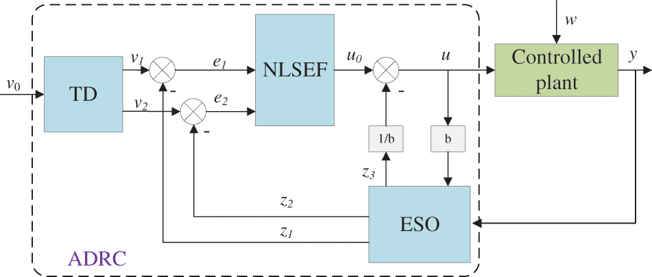
Figure 9: Active disturbance rejection controller structure frame diagram
In Fig. 9, u represents the controllable force F in the state-space Eq. (9), while w denotes the total disturbance acting on the controlled plant, including road excitation and the unbalanced radial electromagnetic force generated by motor static eccentricity. Additionally, y represents the vehicle body acceleration of the controlled system.
In the main design of the Tracking Differentiator (TD). ESO’s main function is to oversee the transitional process of the reference signal, ensuring rapid convergence to the input signal within a finite time while furnishing the derivative signal of this process. The velocity factor determines the pace of the transitional process. The mathematical expression of TD is shown in Eq. (13).
where v0 is the reference signal, v1 is the tracking signal, v2 is the differential signal, r0 is the speed factor, h is the filter factor, and fhan is the fastest comprehensive function.
Because the main purpose of the controller is to improve the suspension performance, and the body acceleration is its main evaluation index, and when the body acceleration is always maintained near 0, the riding comfort of HMDV is the best. Therefore, the reference signal is set as the body acceleration, then v0 = 0, and Eq. (14) can be rewritten.
The concrete expression of fhan is shown in Eq. (15).
In the Extended State Observer (SEO), the internal state variable of the system is determined by the observed number of external variables and the state output of the system is transformed into a variety of output signals, which are input into the control system and the output variable of the controller is changed. Its mathematical expression is shown in Eq. (16).
where δE is the limit to distinguish the size of eE, βE1, βE2 and βE3 are adjustable parameters, b0 is the compensation factor, and fal is the nonlinear function.
The expression of the nonlinear function fal is shown in Eq. (17).
where αE is a nonlinear factor, following the idea of large error small gain, small error large gain, and its range is usually within 0~1.
In the Nonlinear State Error Feedback (NLSEF), the output signal of the tracking differentiator is linearly fitted with part of the output signal from the extended state observer to obtain the error feedback law and its input variables. At the same time, part of the output variables from the extended state observer is taken as compensation variables. Its mathematical expression is shown in Eq. (18).
where δN is the limit to distinguish the size of eN, βN1 and βN2 are tunable parameters, and αN is the same as αE.
The mathematical expression for the disturbance compensation part is shown in Eq. (19).
The PID control algorithm consists of three components: proportional, integral, and derivative. Among them, the proportional component serves to improve system response speed and control accuracy; the integral component eliminates errors; and the derivative component anticipates system deviation, reducing overshoot. Its schematic diagram is shown in Fig. 10.
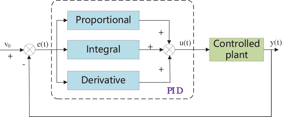
Figure 10: PID control algorithm schematic
The mathematical model expression of the PID control algorithm is shown in Eq. (20).
4.3 Controller Parameter Adjustment
The adjustment of controller parameters determines whether the control effect can be fully exerted. Various parameters of the three main parts in the active disturbance rejection controller (ADRC), including balancing considerations and combining practical experience, can be obtained in a general range for a second-order control system. Additionally, optimization algorithms can be employed to optimize and analyze parameters with a larger range to obtain the optimal parameters [29]. In this study, the goal of implementing ADRC is to improve the suspension performance, and thus, the root mean square values of body acceleration and dynamic tire load are used as control objectives for the optimization algorithm.
In the ADRC, the parameters that need tuning include: In the Tracking Differentiator: The speed factor (r0) and the filtering factor (h) require adjustment. In the Extended State Observer: The compensation factor (b0), linear factor (δE), and observation factors (βE1, βE2, and βE3) need adjustment. In the Nonlinear State Error Feedback: The linear factor (δN) and gain factors (βN1 and βN2) need adjustment. The integration step size (h0) for this control is set to 0.01s. Based on control experience, the filtering factor is set as 4 times the integration step size, the speed factor is set as 0.05, the compensation factor (b0) is in the range of [0.01–10], the linear factor (δE) is set as 0.02, and δN1 and δN2 are set as 0.25 and 0.5, respectively.
The approximate range of the observed factors βE1, βE2 and βE3 can be determined by reference to the approximate expression (21) [16].
The compensation factor (b0), observation factors (βE1, βE2, βE3), and gain factors (βN1, βN2) are optimized using the Particle Swarm Optimization (PSO) algorithm to determine the final optimal parameter values. The PSO algorithm tracks individual and swarm extremums to find the optimal solution, offering advantages such as ease of implementation, rapid convergence, and a stochastic search mechanism. The velocity update and position update formulas of the particles are shown in Eqs. (22) and (23).
where
Taking the controller parameters to be optimized as the optimization parameter set (denoted as z), the optimization objective is defined as the ratio of the root mean square (RMS) value of the performance metric of the inerter suspension system to the RMS value of the performance metric of the traditional suspension system. The optimized target fitness function and constraint conditions are shown in Eqs. (24) and (25).
where BA(z) and DTL(z) are root mean square values of body acceleration and tire dynamic load of dynamic inertial suspension, respectively. BApass and DTLpass are the root-mean-square values of body acceleration and tire dynamic load of traditional passive suspension. α1 and α2 are the optimal weighting coefficients, respectively, and their sum is 1.
The optimized parameter values obtained through multiple optimization calculations by the particle swarm optimization algorithm are shown in Table 4.

5 Performance Analysis of HMDV Controllable Dynamic Inertial Suspension
In the case of a road surface classified as level C, a simulation analysis is conducted on the traditional passive suspension, L4 dynamic inertial suspension, and the controllable dynamic inertial suspension (including PID and ADRC). The dynamic performance of each suspension at a vehicle speed of 20 m/s is obtained, and the respective root mean square values are compared, as shown in Table 5 and Fig. 11.


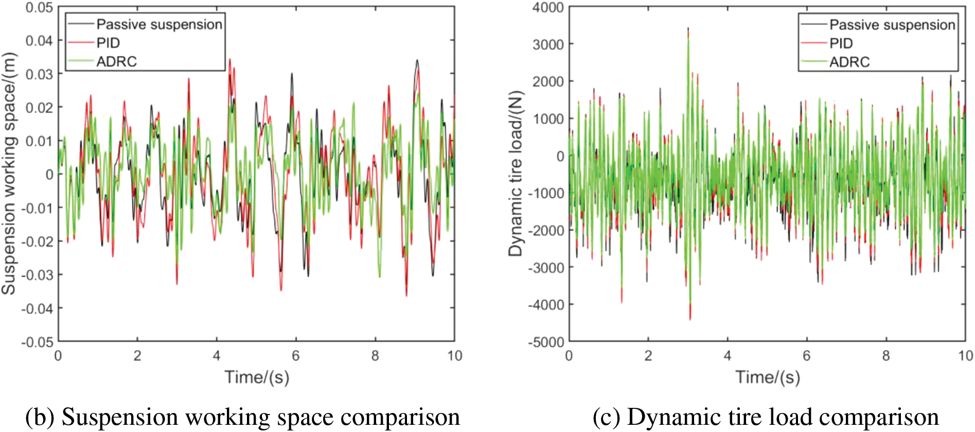
Figure 11: Performance comparison of vehicle speed 20 m/s
From Table 5 and Fig. 11, it can be observed that in the simulation on random road surfaces at a speed of 20 m/s, the performance of various suspension models can be compared through the root mean square values of body acceleration, suspension working space, and dynamic tire load. The controllable dynamic inertial suspension, especially the one based on self-disturbance rejection control (ADRC), exhibits better performance compared to traditional passive suspension and L4 dynamic inertial suspension. The controllable dynamic inertial suspension shows a significant reduction in root mean square values. Specifically, compared to the traditional passive suspension, the PID-based dynamic inertial suspension reduces by 14.61%, while the ADRC-based dynamic inertial suspension reduces by 29.53% in terms of body acceleration root mean square. For suspension working space root mean square, the PID-based dynamic inertial suspension worsens by 7.94%, whereas the ADRC-based dynamic inertial suspension reduces by 20.41% compared to the traditional passive suspension. In terms of dynamic tire load root mean square, the PID-based dynamic inertial suspension increases by 3.33%, while the ADRC-based dynamic inertial suspension reduces by 14.87% compared to the traditional passive suspension. In summary, it is evident that the controllable dynamic inertial suspension based on self-disturbance rejection control has a significant effect on suppressing the adverse effects of wheel motor vertical vibration.
To further analyze the performance of different suspensions, the time-domain response graphs of the car at a speed of 20 m/s were Fourier transformed to obtain the spectral comparison graphs of the three performance indicators for each suspension, as shown in Fig. 12.
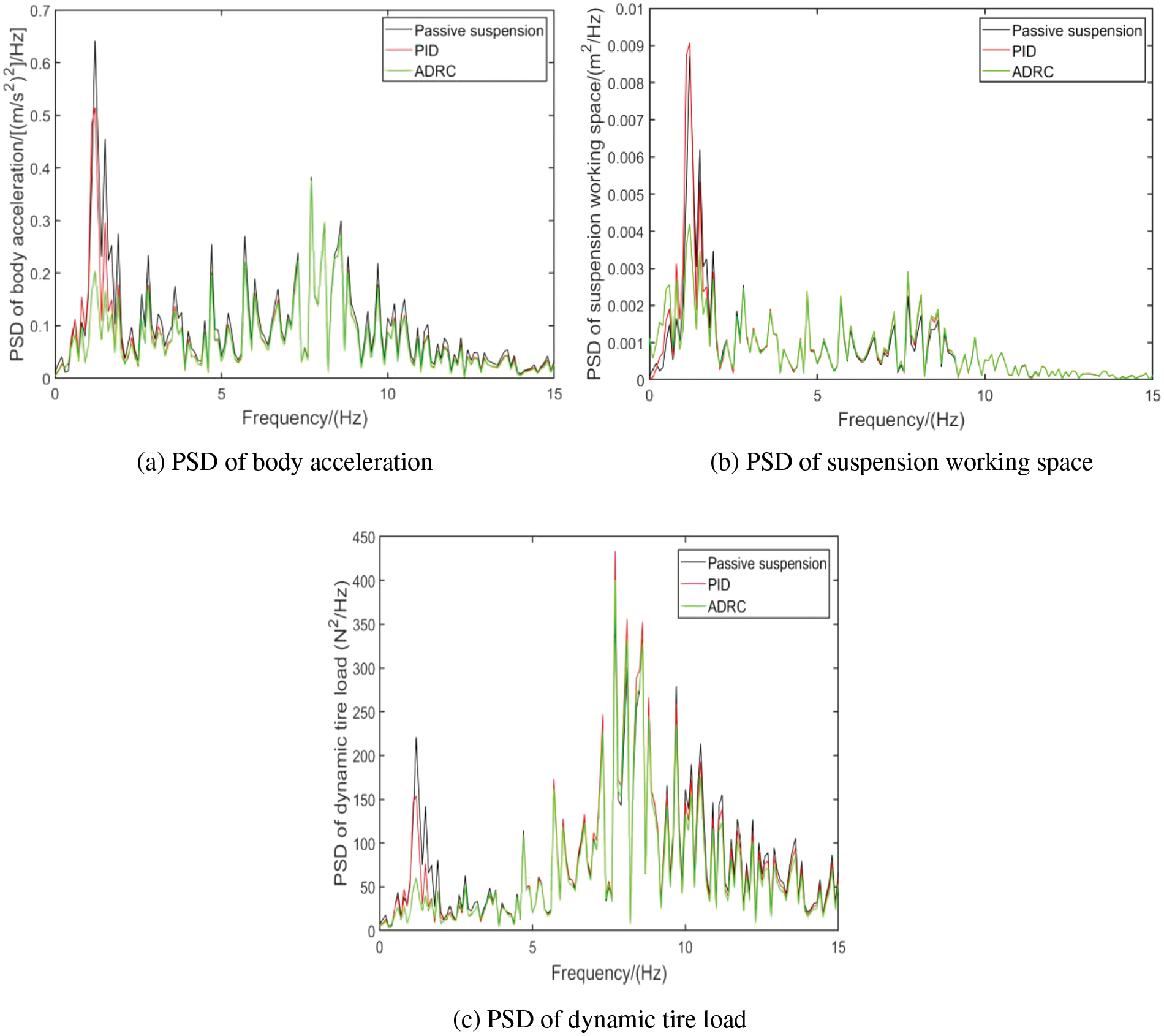
Figure 12: Performance spectrum comparison diagram at a speed of 20 m/s
Analysis of the performance states of various suspensions at different frequencies can be derived from Fig. 12. From Fig. 10a, it can be observed that, in terms of the power spectral density of body acceleration, the controllable dynamic inertial suspension significantly reduces in various frequency ranges compared to the traditional passive suspension. The most significant reductions occur in the 0–2 Hz and 10–15 Hz ranges, especially for the ADRC-based inertial suspension. From Figs. 10b and 10c, it is evident that, in the power spectral density of suspension working space and dynamic tire load, the controllable dynamic inertial suspension exhibits a notable reduction in the 0–2 Hz range compared to the traditional passive suspension and passive inerter suspension, with some reductions in other frequency ranges as well, but the decline is not very significant in the middle and high frequency bands. Overall, it can be concluded that the controllable dynamic inertial suspension has certain performance advantages over the passive suspensions in all three performance indicators. It demonstrates a significant inhibitory effect on the adverse vertical vibration effects induced by the wheel motor, thereby enhancing the ride stability of the wheel motor-driven vehicle.
Under sinusoidal road input with an amplitude of 10 mm and a frequency range of 0.1–15 Hz, the dynamic response of the controllable dynamic inertial suspension is simulated and analyzed. Fig. 13 illustrates the performance comparison under this condition.
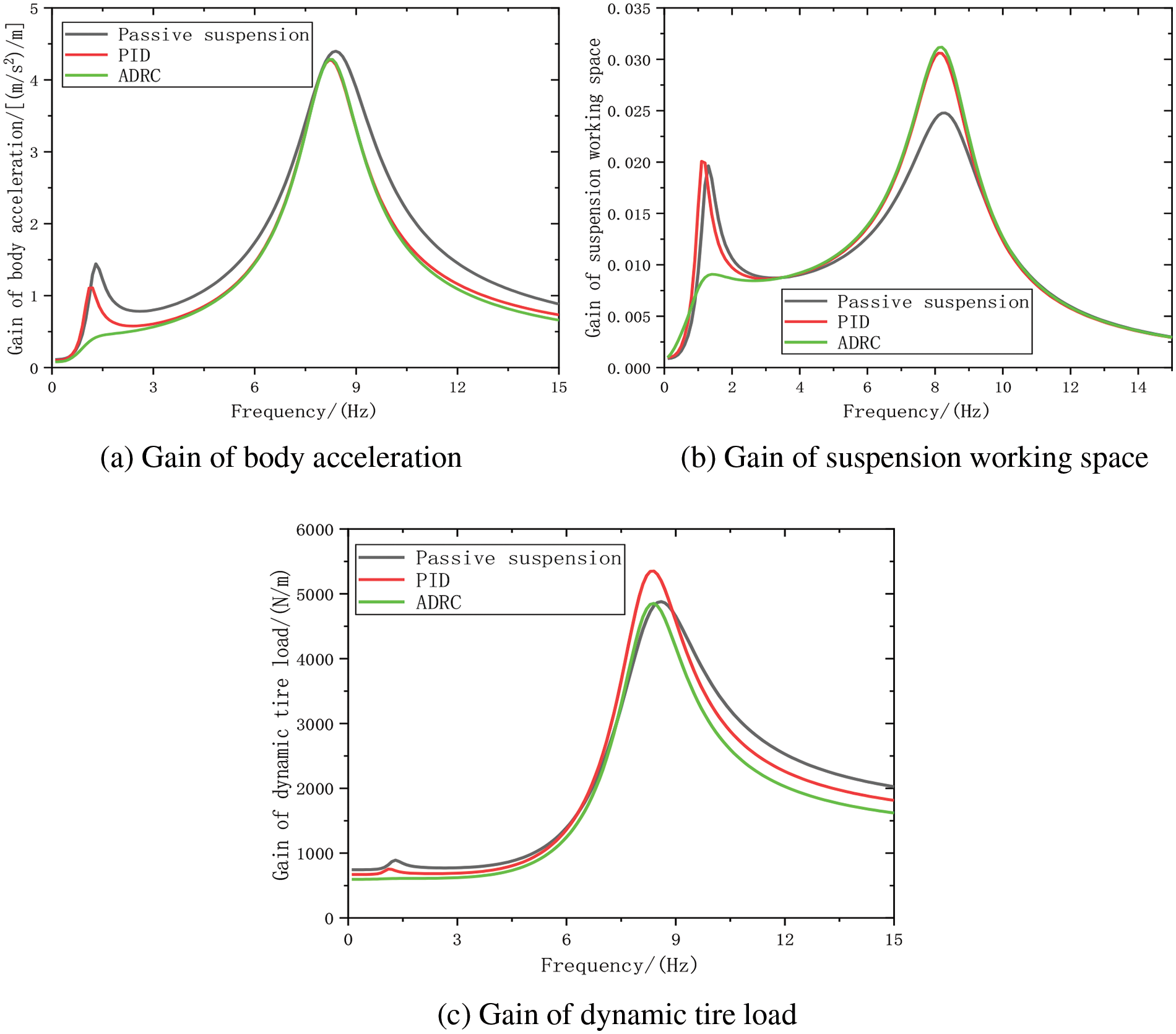
Figure 13: Sinusoidal input suspension gain comparison diagram
Fig. 13 illustrates significant performance differences among the suspensions under sinusoidal road input at various frequency ranges. In terms of the body acceleration gain, the controllable dynamic inertial suspension demonstrates outstanding performance advantages compared to the traditional passive suspension. Overall, it exhibits a noticeable reduction across the entire frequency range, particularly in the frequency bands of 1–7 Hz and 9–15 Hz. Notably, the suspension based on ADRC outperforms the one based on PID control, showing significant reduction advantages in the low, medium, and high-frequency ranges. Specifically, the ADRC-based inertial suspension achieves the lowest gain at the low-frequency resonance peak, with only 0.3176 m/s2, representing a reduction of 52.3% compared to the traditional passive suspension. Concerning the suspension working space gain, in the frequency band of 0.1–3.5 Hz, compared to the traditional passive suspension, the PID-based inertial suspension shows a certain degree of deterioration, while the ADRC-based inertial suspension exhibits a significant improvement, reducing the low-frequency resonance peak by 43.8% compared to the traditional passive suspension. In the middle and high frequency bands, the controlled dynamic inertial suspension deteriorates compared to the passive suspension. In terms of the dynamic tire load gain, in the frequency band of 0.1–6.5 Hz, the controllable dynamic inertial suspension shows a noticeable reduction compared to the traditional passive suspension. Both the PID-based and ADRC-based inertial suspensions reduce the low-frequency resonance peak by 7.6% and 27.7%, respectively. In the 6.5–8.6 Hz range, the controlled dynamic inertial suspension has deterioration compared with the passive suspension, but the performance difference between the three is low. In the frequency band of 8.6–15 Hz, the controllable dynamic inertial suspension exhibits a significant improvement.
In summary, the ADRC-based inertial suspension demonstrates significant performance advantages, providing a notable suppression effect on the vertical vibration negative effects of hub motor-driven vehicles. Combining the increased vertical motion inertia and stability of the dynamic inertial suspension system without adding the system’s weight with the outstanding control performance of ADRC, this study actively explores the performance advantages of the controllable dynamic inertial suspension system under the combined state of both.
This paper addresses the deterioration of vehicle suspension performance due to the negative effects of vertical vibration caused by hub motor-driven vehicles, including vertical vibration and unbalanced radial forces. A dynamic inertial suspension system based on active disturbance rejection control is proposed. Through the integration of active disturbance rejection control and electromechanical inerter, a controllable electromechanical inerter is designed to control the output force of the rotating motor using active disturbance rejection control. This enables real-time adjustment of the electromechanical inerter in the dynamic inertial suspension system, suppressing the negative effects of hub motor-induced vertical vibrations on suspension performance. Simulation results demonstrate that the designed controllable dynamic inertial suspension system, under sinusoidal road input, exhibits a 52.3% reduction in the low-frequency resonance peak in the vehicle body acceleration gain diagram compared to traditional passive suspensions. In the high-frequency range, it shows significant performance optimization. Under random road input, the root mean square values of vehicle body acceleration and tire dynamic loads decrease by 29.53% and 14.87%, respectively. Under the sinusoidal road input, the gain effect of the three performance indicators of suspension can be seen more directly, and the performance gap between them can be fully reflected in different frequency bands, among which the acceleration gain of the body and the dynamic load gain of the tire are more obvious. The controllable dynamic inertial suspension system effectively mitigates the negative effects of vertical vibrations induced by hub motors, significantly improving the smoothness and stability of hub motor-driven vehicles. This provides a novel approach for researching the suppression mechanisms of negative effects on vertical vibrations in HMDVs.
For the subsequent research of this paper, a coupled model of motor eccentricity considering both static and dynamic eccentricity could be established, and further control research on the vehicle model of HMDV could be conducted. Additionally, more in-depth control research on the control system and the incorporation of corresponding stability proofs could be considered.
Acknowledgement: The authors wish to express their appreciation to the reviewers for their helpful suggestions which greatly improved the presentation of this paper.
Funding Statement: Thanks to the following fund funding for this article: the National Natural Science Foundation of China (Grant Numbers 52072157, 52002156, 52202471); Natural Science Foundation of Jiangsu Province (Grant Number BK20200911), Chongqing Key Laboratory of Urban Rail Transit System Integration and Control Open Fund (Grant Number CKLURVIOM_KFKT_2023001), and Jiangsu Funding Program for Excellent Postdoctoral Talent (Grant Number 2022ZB659), and State Key Laboratory of Advanced Design and Manufacturing Technology for Vehicle, Hunan University (Grant Number 82315004).
Author Contributions: The authors confirm their contribution to the paper as follows: study conception and design: Xiaofeng Yang, Wei Wang; data collection: Yujie Shen; analysis and interpretation of results: Changning Liu, Wei Wang; draft manuscript preparation: Tianyi Zhang. All authors reviewed the results and approved the final version of the manuscript.
Availability of Data and Materials: The datasets used and/or analysed during the current study are available from the corresponding author on reasonable request.
Conflicts of Interest: The authors declare that they have no conflicts of interest to report regarding the present study.
References
1. Li Z, Zheng L, Gao W, Zhan ZF. Electromechanical coupling mechanism and control strategy for in-wheel motor driven electric vehicles. IEEE Trans Ind Electron. 2018;66(6):4524–33. [Google Scholar]
2. Guo L, Khiu A, Fan RL, Wang X. Analysis of a passive scissor-like structure isolator with quasi-zero stiffness for a seating system vibration-isolation application. Int J Veh Des. 2020;82(1–4):224–40. [Google Scholar]
3. Jiang C, Yu S, Xie HC, Li BC. Interval uncertain optimization of vehicle suspension for ride comfort. Comput Model Eng Sci. 2014;98(4):443–67. doi:10.3970/cmes.2014.098.443. [Google Scholar] [CrossRef]
4. Narwade P, Deshmukh R, Nagarkar M, Sukhwani V. Improvement of ride comfort in a passenger car using magneto rheological (MR) damper. J Vibr Eng Technol. 2022;10(7):2669–76. doi:https://doi.org/10.1007/s42417-022-00512-0. [Google Scholar] [CrossRef]
5. Yu M, Cheng C, Evangelou S, Dini D. Series active variable geometry suspension: full-car prototyping and road testing. IEEE/ASME Trans Mechatron. 2021;27(3):1332–44. [Google Scholar]
6. Fu CZ, Lu JY, Ge WQ, Tan C, Li B. A review of electromagnetic energy regenerative suspension system & key technologies. Comput Model Eng Sci. 2023;135(3):1779–824. doi:10.32604/cmes.2022.023092. [Google Scholar] [CrossRef]
7. Smith MC, Wang FC. Performance benefits in passive vehicle suspensions employing inerters. Veh Syst Dyn. 2004;42(4):235–57. doi:https://doi.org/10.1080/00423110412331289871. [Google Scholar] [CrossRef]
8. Liu CN, Chen L, Lee HP, Yang Y, Zhang XL. A review of the inerter and inerter-based vibration isolation: theory, devices, and applications. J Franklin Inst. 2022;359(44):7677–707. [Google Scholar]
9. Ma RS, Bi KM, Hao H. Inerter-based structural vibration control: a state-of-the-art review. Eng Struct. 2021;243:112655. doi:https://doi.org/10.1016/j.engstruct.2021.112655. [Google Scholar] [CrossRef]
10. Baduidana M, Kenfack-Jiotsa A. Optimal design of inerter-based isolators minimizing the compliance and mobility transfer function versus harmonic and random ground acceleration excitation. J Vib Control. 2021;27(11–12):1297–310. [Google Scholar]
11. Shen YJ, Hua J, Fan W, Liu YL, Yang XF, Chen L. Optimal design and dynamic performance analysis of a fractional-order electrical network-based vehicle mechatronic ISD suspension. Mech Syst Signal Process. 2022;184:109718. [Google Scholar]
12. Alotta G, Failla G. Improved inerter-based vibration absorbers. Int J Mech Sci. 2021;192:106087. doi:https://doi.org/10.1016/j.ijmecsci.2020.106087. [Google Scholar] [CrossRef]
13. Wang J, Wang B, Liu Z, Zhang C, Li HB. Experimental and numerical studies of a novel asymmetric nonlinear mass damper for seismic response mitigation. Struct Control Health Monit. 2020;27(4):e2513. [Google Scholar]
14. Song J, Bi KM, Ma RS, Xu K, Han Q. Optimum design and performance evaluation of inerter-based dampers for seismic protection of adjacent bridges. Structures. 2023;55:1277–91. doi:https://doi.org/10.1016/j.istruc.2023.06.093. [Google Scholar] [CrossRef]
15. Wang Y, Li HX, Meng HD, Wang Y. Dynamic characteristics of underframe semi-active inerter-based suspended device for high-speed train based on LQR control. Bull Polish Acad Sci Tech Sci. 2022;70(4):e141722. [Google Scholar]
16. Han J. Active disturbance rejection control technique-the technique for estimating and compensating the uncertainties. China: National Defense Industry Press; 2008. p. 5–145 (In Chinese). [Google Scholar]
17. Han J. From PID to active disturbance rejection control. IEEE Trans Ind Electron. 2009;56(3):900–6. doi:https://doi.org/10.1109/TIE.2008.2011621. [Google Scholar] [CrossRef]
18. Wu ZL, Shi GJ, Li DH, Liu YH, Chen YQ. Active disturbance rejection control design for high-order integral systems. ISA Trans. 2021;125:560–70. [Google Scholar] [PubMed]
19. Guevara L, Jorquera F, Walas K, Auat-Cheein F. Robust control strategy for generalized N-trailer vehicles based on a dual-stage disturbance observer. Control Eng Pract. 2022;131:105382. [Google Scholar]
20. Roman RC, Precup RE, Petriu EM, Anamaria-Ioana B. Hybrid data-driven active disturbance rejection sliding mode control with tower crane systems validation. Roman J Inf Sci Technol. 2024;27(1):50–64. [Google Scholar]
21. Tian MH, Wang B, Yu Y, Dong QH, Xu DG. Discrete-time repetitive control-based ADRC for current loop disturbances suppression of PMSM drives. IEEE Trans Ind Inform. 2022;18(5):3138–49. doi:https://doi.org/10.1109/TII.2021.3107635. [Google Scholar] [CrossRef]
22. Zhou W, Guo S, Guo J, Chen ZY, Meng FX. Kinetics analysis and ADRC-based controller for a string-driven vascular intervention surgical robotic system. Micromachines. 2022;13(5):770. doi:https://doi.org/10.3390/mi13050770. [Google Scholar] [PubMed] [CrossRef]
23. Sun X, Shi Z, Cai Y, Lei G, Guo YG, Zhu JG. Driving-cycle-oriented design optimization of a permanent magnet hub motor drive system for a four-wheel-drive electric vehicle. IEEE Trans Transp Electrif. 2020;6(3):1115–25. doi:https://doi.org/10.1109/TTE.6687316. [Google Scholar] [CrossRef]
24. Wang HH. Speed control technology of switched reluctance motor. China: Beijing Industry Press; 1999. p. 7–166 (In Chinese). [Google Scholar]
25. Li J, Jia CW, Cheng LH, Zhao Q. Influence of in-wheel motors’ eccentricity on ride comfort of electric vehicles on random roads. J Northeastern Univ. Nat Sci. 2022;43(8):1113–9 (In Chinese). [Google Scholar]
26. Feng GZ, Li SH, Zhao WZ. Electromechanical coupling modelling and nonlinear vibration analysis of an electric vehicle-road system. J Vibr Shock. 2021;40:18–26+76 (In Chinese). [Google Scholar]
27. Minorsky N. Directional stability of automatically steered bodies. J Am Soc Naval Eng. 1922;34(2):280–309. doi:https://doi.org/10.1111/nej.1922.34.issue-2. [Google Scholar] [CrossRef]
28. Chi RH, Li HY, Shen D, Hou ZS, Huang B. Enhanced P-type control: indirect adaptive learning from set-point updates. IEEE Trans Automat Contrl. 2023;68(3):1600–13. doi:https://doi.org/10.1109/TAC.2022.3154347. [Google Scholar] [CrossRef]
29. Zhang YJ, Fan CD, Zhao FF, Ai ZY, Gong ZH. Parameter tuning of ADRC and its application based on CCCSA. Nonlinear Dyn. 2014;76(2):1185–94. doi:https://doi.org/10.1007/s11071-013-1201-4. [Google Scholar] [CrossRef]
Cite This Article
 Copyright © 2024 The Author(s). Published by Tech Science Press.
This work is licensed under a Creative Commons Attribution 4.0 International License , which permits unrestricted use, distribution, and reproduction in any medium, provided the original work is properly cited.


 Submit a Paper
 Propose a Special lssue
 View Full Text
 Download PDF
 Downloads
 Citation Tools