
 Submit a Paper
 Propose a Special lssue
 Open Access
ARTICLE

Hybrid Strategy of Partitioned and Monolithic Methods for Solving Strongly Coupled Analysis of Inverse and Direct Piezoelectric and Circuit Coupling
Department of Intelligent and Control Systems, Kyushu Institute of Technology, Fukuoka, Japan
* Corresponding Author: Daisuke Ishihara. Email:
Computer Modeling in Engineering & Sciences 2024, 140(2), 1371-1386. https://doi.org/10.32604/cmes.2024.049694
Received 15 January 2024; Accepted 10 March 2024; Issue published 20 May 2024
 View Full Text
 Download PDF
Abstract
The inverse and direct piezoelectric and circuit coupling are widely observed in advanced electro-mechanical systems such as piezoelectric energy harvesters. Existing strongly coupled analysis methods based on direct numerical modeling for this phenomenon can be classified into partitioned or monolithic formulations. Each formulation has its advantages and disadvantages, and the choice depends on the characteristics of each coupled problem. This study proposes a new option: a coupled analysis strategy that combines the best features of the existing formulations, namely, the hybrid partitioned-monolithic method. The analysis of inverse piezoelectricity and the monolithic analysis of direct piezoelectric and circuit interaction are strongly coupled using a partitioned iterative hierarchical algorithm. In a typical benchmark problem of a piezoelectric energy harvester, this research compares the results from the proposed method to those from the conventional strongly coupled partitioned iterative method, discussing the accuracy, stability, and computational cost. The proposed hybrid concept is effective for coupled multi-physics problems, including various coupling conditions.Keywords
In piezoelectric materials, the electric charge is accumulated in response to mechanical strain, termed the direct piezoelectric effect, while the material changes size in response to an applied electrical potential, known as the inverse piezoelectric effect [1], and these effects interact with each other. These effects have been utilized to develop sensors and actuator devices in various electro-mechanical systems such as piezoelectric energy harvesters [2], robotic applications [3,4], biomimetic robots [5,6], piezoelectric-actuated microgrippers [7,8], and precision drive systems [9,10]. The piezoelectric device and the circuit are integrated and interact in these systems. Hence, their electro-mechanical behavior is formulated as the coupled inverse and direct piezoelectric and circuit interaction.
This coupling phenomenon has been addressed using simplified models such as the Euler-Bernoulli beam theory for the structural element [11], the weakly coupled model for structural and piezoelectric coupling [12], the equivalent capacitance approximation for the piezoelectric continuum [13], and a lumped circuit model analytically derived with three degrees of freedom for modeling the mechanical-to-electrical conversion by a serial bimorph piezoelectric cantilever as an extension of the single degree of freedom model [14], among others. These models have been effectively used to derive both analytical and numerical solution methods. However, direct numerical modeling of this coupling phenomenon will be vital in designing advanced electro-mechanical systems [15–18]. The term ‘direct’ indicates that the governing equations are not transformed into a different form prior to spatial finite element discretization [19].
Due to its strong electro-mechanical conversion characteristics, considerable attention has been devoted to the piezoelectric energy harvesting device [20]. The most typical model of this device is a thin cantilever bimorph consisting of two piezoelectric and one intermediate metal layer [11]. Despite the simple configuration of this model, the strongly coupled analysis method based on direct numerical modeling is required for accurate prediction of the electro-mechanical behavior due to the inverse and direct piezoelectric coupling [21], the complex distribution of the induced electrical potential [22], significant three-dimensional deformation [21], and the strongly coupled piezoelectric oscillator and circuit [23].
Initially, the monolithic method was proposed in studies on direct numerical modeling for inverse and direct piezoelectric and circuit coupling [15], where the discretized governing equations were formulated as a single equation system. The coupling conditions are solved accurately in monolithic analysis since the monolithic formulation satisfies them directly. However, partitioned analysis appears to be computationally efficient [24]. In addition, existing codes can be reused for partitioned analysis due to software modularity. Hence, the strongly coupled partitioned iterative method was proposed based on direct numerical modeling for inverse and direct piezoelectric and circuit coupling [23]. This method decomposes all fields and satisfies their coupling conditions using the iterative method. The partitioned algorithm is strongly coupled if the coupling terms are corrected to sufficient accuracy [25,26]. This coupling condition can be achieved if coupling iterations or inter-field iterations are performed and the iterative procedure is convergent [27,28]. However, the partitioned analysis of piezoelectricity and circuit imposes a critical time increment smaller than the time constant of the general RC circuit on the time increment as the convergence condition [23].
Accordingly, this study proposes a new method that combines the best features of the partitioned and monolithic formulations, i.e., the hybrid partitioned-monolithic method. The analysis of inverse piezoelectricity and the monolithic analysis of direct piezoelectric and circuit interaction are strongly coupled using the block Gauss-Seidel (BGS) algorithm. Considering typical benchmark problems, we compare the results from the proposed method with those from the conventional strongly coupled partitioned iterative method and the analytical solutions and discuss the accuracy, convergence properties, and computational cost.
2 Structure-Piezoelectric-Circuit Interaction
The circuit-integrated piezoelectric device is schematically shown in Fig. 1, where the piezoelectric device is connected to the circuit via electrodes. The pseudo-piezoelectric material modeling [22], which sets the piezoelectric constant matrix to 0 and the dielectric constant matrix to 1, is used for the electrical conductor domain. This approach ensures that the system is governed by the common equations for inverse and direct piezoelectric and circuit coupling.

Figure 1: Circuit-integrated piezoelectric device
2.1 Piezoelectric Material Equations
The equilibrium equations for a piezoelectric continuum are described as follows:
where σij is the mechanical stress tensor component, fi and Di are the body force and electric displacement vector components, respectively, and, ‘j’ is the differential with respect to the j-th coordinate. σij and Di are provided by the following linear piezoelectricity constitutive equations.
where Cijkl, eijk, Sij, and εij are the tensor components of elasticity, piezoelectric constant, mechanical strain, and dielectric constants, respectively, and Ei is the electric field vector component. The superscript E indicates that the quantity is determined under the constant electric field, and the superscript S indicates that the quantity is determined under the constant mechanical strain field. Sij and Ei are respectively expressed as follows:
where ui is the i-th vector component of the mechanical displacement, and φ is the electric potential.
Eqs. (1) through (6) are spatially discretized in the global coordinate system using the standard finite element formulation.
where Muu is the global matrix of the mechanical mass, Kuu is the global matrix of the mechanical stiffness, Ku
Shell elements are efficient for analyzing the bending of a thin bimorph structure, whereas solid elements are necessary for describing complicated electricity [22]. Hence, the analysis of inverse piezoelectricity for Eq. (7) uses the shell elements (referred to as the shell analysis of inverse piezoelectricity), while the analysis of direct piezoelectricity for Eq. (8) uses the solid elements [22] (referred to as the solid direct piezoelectric analysis). Their resultant nodal properties are exchanged as follows: the electrical forces of the latter are changed to the shell mechanical forces and moments using their balances, while the mechanical displacements of the former are changed to those of the solid mesh using the finite element shape function. The former uses modeling the piezoelectric bimorph composite as a single shell structure, evaluating effective properties using the homogenization method [22].
The electrical resistive load is considered the electric circuit in Fig. 1. The single-degree-of-freedom governing equation can be described as follows:
where R is the electric resistance, Q is the electric charge, Vp is the electric potential gap between the electrodes given by the piezoelectric continuum, and Ve is the external electric voltage.
2.3 Continuity Conditions between Piezoelectric Material and Circuit
The continuity conditions between the piezoelectric material and the circuit are imposed on the interface. Assuming the instantaneous distribution of charges in electrodes, these equations can be described as follows:
where S+c and S-c are the areas of the electrodes; the subscripts + and − correspond to the positive and negative poles defined in the general circuit expression, respectively; φx* (x is + or −) is the electric potential at a point in Sxc where the circuit is connected; and N
3 Hybrid Partitioned-Monolithic Method
The electro-mechanical system can be partitioned into mechanical and electrical subsystems, with the electrical subsystem further partitioned into the piezoelectric continuum and the circuit. Following this hierarchical decomposition, a previous study [23] solved the electrical subsystem using a partitioned iterative algorithm (either the conventional strongly coupled partitioned iterative method or the fully partitioned method). However, for the coupling iteration to converge, the critical value using the circuit characteristic time must be met by the time increment. Therefore, the coupled piezoelectric and circuit interaction is monolithically analyzed in this study. Hierarchically, the analysis of inverse piezoelectricity for the mechanical subsystem and the monolithic analysis for the electrical subsystem are strongly coupled using a partitioned iterative algorithm (the hybrid partitioned-monolithic method). Fig. 2 shows the conceptual view of the hybrid partitioned-monolithic method proposed in the current study.

Figure 2: Conceptual view of the hybrid partitioned-monolithic method
Substituting the relationships among the state variables given by Newmark’s β method [19] into Eqs. (7) and (8), they can be rearranged as follows:
where
Applying the generalized trapezoidal rule for Eq. (9), it can be rearranged as follows:
3.2 Interface Degrees of Freedom Transformation Matrices between Piezoelectric Continuum and Circuit
The continuity or coupling conditions (10) and (11) can be expressed as follows:
where the matrices Tp and Tc are given, respectively.
The formulation of Tc in Eq. (20) is given by taking out the common factor Q of the terms in the right-hand side of Eq. (11). Conversely, the formulation of Tp has a wide variation. This study uses the formulation equivalent to that for the equivalent nodal force for the surface force. Then, Eq. (19) for the formulation of Tp is provided such that it satisfies the relationship of
3.3 Monolithic Equation for Coupled Piezoelectric and Circuit Interaction
The direct piezoelectric Eq. (13) and the circuit Eq. (9) are combined using the coupling conditions (17) and (18), and their monolithic equation can be provided as follows:
where
Solving Eq. (21) corresponds to the monolithic analysis of the coupled piezoelectric and circuit interaction. Hierarchically, Eqs. (12) and (21) are strongly coupled using the partitioned iterative algorithm in the next section.
3.4 Partitioned Analysis of Mechanical and Electrical Subsystems
Applying the BGS algorithm to Eqs. (12) and (21) yields the following equations:
where i is the i-th BGS iteration. The proposed hybrid partitioned-monolithic method is shown in Fig. 2. In each BGS iterative step, firstly, the inverse piezoelectric Eq. (24) is solved to obtain the current displacement
where n is the number of each node, and N denotes the number of nodes.
In the conventional fully partitioned method [23], the partitioned method is also utilized for the coupled piezoelectric and circuit interaction, as shown in Fig. 2. If the partitioned method is applied for the coupled piezoelectric and circuit interaction, the following condition must be satisfied by the time increment Δt for the convergent coupling iteration [23]:
where Δtc is the critical time increment, and Cp is the effective parameter of the capacitance of the piezoelectric material. Unlike the fully partitioned method [23], this condition is not imposed on the proposed hybrid method.
4 Numerical Tests Using Typical Piezoelectric Energy Harvester Model
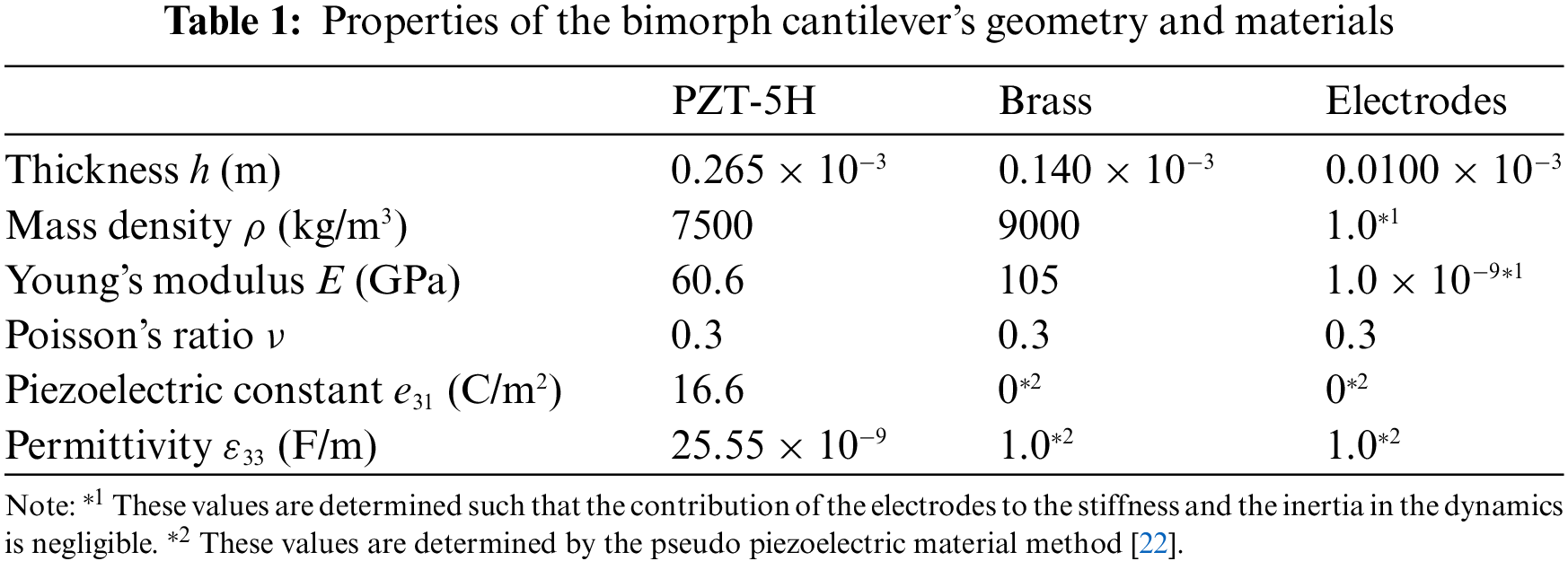
A typical piezoelectric energy harvester model in Fig. 3 [11] is considered. In this figure, the cantilevered beam is a symmetric bimorph with three layers. The outer two piezoelectric (PZT-5H) layers of each bimorph are poled oppositely in the thickness direction for the series connection of the electrical outputs. The electrodes covering the surfaces are sufficiently thin compared to each bimorph. Table 1 summarizes the material properties of these layers. The resistive load R is connected to the electrodes. In Sections 4.2.1, 4.2.2, and 4.2.3, R is set as 470 Ω, the smallest among the experimental values used in the literature [11], to consider the very small Δtc. In addition, Section 4.2.4 considers the general value of R to discuss the range of R where the proposed method is efficient. The harmonic translation (the acceleration level g = 9.81 m/s2) is applied to the cantilever at the base in the out-of-plane direction.

Figure 3: Typical model of the piezoelectric energy harvesting device
The electro-mechanical responses of the piezoelectric micro-components show size dependency [29,30]. In Fu et al. [30], the microbeam with the thickness
Fig. 3 indicates that the mass can be added to the tip of the cantilever beam. In the case with the added mass, the weight is set at 0.239 g and positioned at the tip, a short length of which half the longitudinal length is given as Lt = 0.25 mm. The length of the added mass area is about 1% of the total longitudinal length of the beam L = 24.53 mm, and the gravity center of the added mass area is equivalent to the center of the tip section of the beam. The width of the beam b is set at 6.4 mm. Table 1 summarizes the thickness of each layer. In the analysis for the model with the added mass, the added mass density is set for the added mass domain, while in the analysis for the model without the added mass, this area is removed from the finite element model.
The mechanical damping in the experiment used for comparison [11] is considered using the mass-proportional damping ratio γ, which can be formulated as [15]
where γ is equal to 2ζωn, ζ is the damping ratio, and ωn is the natural angular frequency. Without the added mass, the theoretical value of ωn is 3157.9 rad/s, corresponding to the natural frequency fn = 502.6 Hz. In the case with the added mass, the theoretical value of ωn is 2137.3 rad/s, corresponding to fn = 340.2 Hz. The damping ratios for the cases without and with the added mass were ζ = 0.00874 rad m/s and 0.00845 rad m/s, respectively, in the corresponding experiment [11].
Mixed Interpolation of Tensorial Components [19] and hexahedral 20-node elements are used for the shell inverse and solid direct piezoelectric analyses, respectively. The in-plane divisions of meshes are 10 and 1, respectively, along the axial and width directions. The division of the solid mesh is 10 along the out-of-plane direction (3 for each PZT-5H layer, 2 for the brass layer, and 1 for each electrode). The time integration parameters are set at β = 0.5 and γ = 0.5 for the unconditionally stable setup of the employed time integration methods. Nevertheless, in the case of the fully partitioned method [23], Δtc = 7.11 × 10⁻⁶ s is imposed on Δt following Eq. (27).
4.2.1 Basic Behaviors of Typical Piezoelectric Energy Harvester Model
Firstly, to demonstrate the proposed hybrid method’s capability to simulate the basic behaviors of the typical piezoelectric energy harvester model, the time history of the transverse displacement of the bimorph’s tip relative to its base and its close-up view are obtained using the proposed hybrid method, as shown in Figs. 4A and 4B. Similarly, the time history of the voltage at the resistive load and its close-up view are obtained using the proposed hybrid method, as shown in Figs. 4C and 4D. A time increment

Figure 4: Time histories of the transverse displacement of the bimorph’s tip relative to its base (A and B) and the electric potential difference at the resistive load (C and D) for the piezoelectric bimorph energy harvester model with the added mass
4.2.2 Accuracy of Proposed Hybrid Method
The solutions are compared to those given by the fully partitioned method [23] and the analytical solutions [11] to illustrate the accuracy of the proposed hybrid method. Figs. 4B and 4D exhibit that the time histories provided by the proposed and conventional strongly coupled partitioned iterative methods are indistinguishable for the base excitation using the resonance frequency. In order to confirm the same level of accuracy of the proposed hybrid method for the wide range of the base excitation frequency, the frequency response functions (FRFs) are compared to those described by the fully partitioned method [23] and their analytical solutions [11]. Figs. 5A and 5B are the FRFs for the transverse displacement of the bimorph’s tip relative to its base, and Figs. 5C and 5D are the FRFs for the voltage at the resistive load. Figs. 5A and 5C are the FRFs for the case without the added mass, whereas Figs. 5B and 5D are the FRFs for the case with the added mass. The time increment

Figure 5: Frequency response functions of the transverse displacement of the bimorph’s tip relative to its base (A and B) and the electric potential difference at the resistive load (C and D) for the piezoelectric bimorph energy harvester model with no added mass (A and C) and with the added mass (B and D)
Figs. 5A and 5C indicate that the resonance frequency for the case without the added mass is determined to be f = 510.6 Hz. At the resonance, the mechanical displacement amplitude measures 82.13 μm, and the voltage amplitude of the electric vibration is 0.125 V. These results, obtained using the proposed hybrid and conventional strongly coupled partitioned iterative methods, coincide. In the case with the added mass, as illustrated in Figs. 5B and 5D, the mechanical displacement amplitude measures 149.6 μm, and the voltage amplitude of the electric vibration is 0.197 V at the resonance frequency of f = 344.2 Hz. These results, derived from the proposed hybrid and conventional strongly coupled partitioned iterative methods, coincide. In both mechanical and electric FRFs, the resonance frequency in the case with the added mass is lower than that without the added mass, and the amplitude in the case with the added mass is higher than that in the case without the added mass. According to these outcomes, following the fundamental characteristics of mechanical forced vibration, the presence of the added mass decreases the resonance frequency and increases the displacement amplitude of the mechanical FRF. Concurrently, the voltage amplitude of the electric FRF increases due to the direct piezoelectric effect. As indicated in Fig. 5, the FRFs provided by the proposed and conventional strongly coupled partitioned iterative methods are indistinguishable. In addition, the numerical FRFs closely match the analytical FRFs, demonstrating the sufficient accuracy of the proposed hybrid method.
4.2.3 Numerical Characteristics of Proposed Hybrid Method
The solution’s dependency on the time increment was examined to show the numerical characteristics of the proposed hybrid method. Fig. 6 displays the step-by-step change in the electric charge of the circuit during the block Gauss-Seidel (BGS) iteration of the fully partitioned method, employing time increments Δt larger than Δtc are used. As shown in this figure, the convergent result cannot be obtained from the fully partitioned method for

Figure 6: Transitions of the electric charge in the circuit of the piezoelectric energy harvesting model, without added mass in the block Gauss-Seidel loop of the initial time step for the fully partitioned method, use various time increments

Figure 7: Frequency response functions of the transverse displacement of the bimorph’s tip relative to its base for piezoelectric energy harvesting models without added mass (A) and with added mass (B) are given by the proposed hybrid method using various time increments
Tables 2 and 3 list the resonance frequencies and the corresponding displacement amplitudes of the mechanical Frequency Response Functions (FRFs) and the corresponding voltage amplitudes of the electric FRFs for various time increments. These tables show that the resonant states for Δt = 1.0 × 10⁻⁶ s using the fully partitioned and proposed hybrid methods are very close. Furthermore, the solutions given by the proposed hybrid method can be considered sufficiently accurate for Δt = 1.0 × 10⁻⁴ s. In both cases, without and with added mass, as shown in Tables 2 and 3, the resonant frequencies for Δt = 1.0 × 10⁻⁶ s and 1.0 × 10⁻⁵ s are equal to each other to the fourth digit, the relative difference of the corresponding displacement amplitude for Δt = 1.0 × 10⁻⁵ s to that for 1.0 × 10⁻⁶ s is about 0.01%, and the relative difference of the corresponding voltage amplitude for Δt = 1.0 × 10⁻⁵ s to that for 1.0 × 10⁻⁶ s is about 0.01%. Hence, the solution for Δt = 1.0 × 10⁻⁶ s can be considered convergent. Fig. 8 shows the relative errors of the solutions for various Δt, where the solution for Δt = 1.0 × 10⁻⁶ s is used as the reference solution. As shown in Fig. 8, the relative error of the solution for Δt = 1.0 × 10⁻⁴ s is less than a few percent. Hence, the proposed hybrid method can be very efficient for analyzing the problem of inverse and direct piezoelectric and circuit coupling since it can use a time increment of 100 times larger Δt with sufficient accuracy than that provided by the fully partitioned method [23].


Figure 8: Relative errors between the solution for Δt = 1.0 × 10⁻⁶ s and that for various time increments in each property in the cases without the added mass (A) and with the added mass (B)
4.2.4 Resistive Road Range for Efficient Analysis of Proposed Method
Finally, this study considers the range of the resistive load R where the proposed method is efficient. The piezoelectric bimorph energy harvester model with no added mass is considered here. A time increment td that can provide sufficiently accurate solutions is defined. In the present problem, with the base excitation frequency near resonance, td can be expressed as
since ωopt is close to ωn and k2 is much smaller than 1. For the present problem, Cp is given as 7.568 × 10⁻⁹ F, and ωn is given as 3.1579 × 10³ rad/s, and Eq. (29) gives Ropt = 41.8 kΩ, which is close to 44.9 kΩ resulting in the strongest attenuation of the peak vibration amplitude in the corresponding experiment by Erturk et al. [11]. Fig. 9 shows the FRFs with R = 44.9 kΩ (close to Ropt) and 995 kΩ (the largest among the experimental values used in the literature [11]), and 470 Ω (the smallest among the experimental values used in the literature [11]) obtained using the proposed method and the theoretical solution [11]. R = 44.9 kΩ near Ropt provides strong attenuation, and the resonant frequency changes with R. The condition

Figure 9: Frequency response functions (FRFs) of the transverse displacement of the bimorph’s tip relative to its base (A) and the electric potential difference at the resistive load (B) for the piezoelectric bimorph energy harvester model with no added mass are analyzed
In the present problem,
This study proposes a hybrid partitioned-monolithic method for the strongly coupled analysis of the structure, piezoelectric, and circuit interaction in advanced electro-mechanical systems. The proposed hybrid method combines the best features of existing partitioned and monolithic formulations based on hierarchical decomposition, where the analysis of inverse piezoelectricity and the monolithic analysis of the coupling of the piezoelectric continuum and the electric circuit are strongly coupled using a partitioned iterative algorithm. The critical time increment, equivalent to the time constant of the general RC circuit, must be satisfied by the partitioned method for direct piezoelectric and circuit coupling. In contrast, this constraint does not restrict the proposed hybrid method since it formulates monolithically direct piezoelectric and circuit coupling. The direct piezoelectric and circuit equations are combined using the interface conditions, and the monolithic equation system for the piezoelectric-circuit coupling is solved directly.
The proposed hybrid method is applied to the numerical analyses of cantilevered piezoelectric energy harvester models, which are typical benchmark problems, and the resulting solutions are very accurate in comparison to those from the theoretical and previous strongly coupled partitioned iterative methods across a wide range of base exciting frequencies. In these analyses, the proposed hybrid method is computationally efficient since the time increment is not restricted by the circuit’s time constant. More specifically, the resistive load for which the proposed method is more efficient than the conventional fully partitioned method is smaller than that comparable with the matched impedance.
In general, coupled multi-physics problems include various types of coupling conditions, and the formulations suitable for these conditions differ. Hence, the proposed hybrid concept will be universal for these problems. Future work will apply methods based on this hybrid concept to coupled multi-physics problems, each consisting of three or more phenomena.
Acknowledgement: The authors thank the support from the Japan Society for the Promotion of Science.
Funding Statement: This research was supported by the Japan Society for the Promotion of Science, KAKENHI Grant No. 23H00475.
Author Contributions: The authors confirm their contribution to the paper as follows: study conception and design: D. Ishihara, T. Niho; data collection: S. Nozaki; analysis and interpretation of results: D. Ishihara, S. Nozaki, N. Takayama; draft manuscript preparation: D. Ishihara. All authors reviewed the results and approved the final version of the manuscript.
Availability of Data and Materials: The datasets analyzed during the current study are available from the corresponding author upon reasonable request.
Conflicts of Interest: The authors declare that they have no conflicts of interest to report regarding the present study.
1. Moulson, A. J., Herbert, J. M. (2003). Electroceramics: Materials, properties, applications, 2nd Edition. England: John Wiley & Sons. [Google Scholar]
2. Matsuda, H., Tanaka, Y., Patel, R., Doi, Y. (2017). Harvesting flow-induced vibration using a highly flexible piezoelectric energy device. Applied Ocean Research, 68, 39–52. https://doi.org/10.1016/j.apor.2017.08.004 [Google Scholar] [CrossRef]
3. Wu, Z., Bao, X. Q., Varadan, V. K., Varadan, V. V. (1992). Light-weight robot using piezoelectric motor, sensor and actuator. Smart Materials and Structures, 1, 330. https://doi.org/10.1088/0964-1726/1/4/008 [Google Scholar] [CrossRef]
4. Zhanga, X., Zhanga, G., Nakamura, K., Ueha, S. (2011). A robot finger joint driven by hybrid multi-DOF piezoelectric ultrasonic motor. Sensors and Actuators A, 169, 206–210. https://doi.org/10.1016/j.sna.2011.05.023 [Google Scholar] [CrossRef]
5. Wood, R. J., Finio, B., Karpelson, M., Ma, K., Pérez-Arancibia, N. O. et al. (2012). Progress on ‘pico’ air vehicles. The International Journal of Robotics Research, 31(11), 1292–1302. https://doi.org/10.1177/0278364912455073 [Google Scholar] [CrossRef]
6. Rios, S. A., Fleming, A. J., Yong, Y. K. (2018). Monolithic piezoelectric insect with resonance walking. IEEE/ASME Transactions on Mechatronics, 23(2), 524–530. https://doi.org/10.1109/TMECH.2018.2792618 [Google Scholar] [CrossRef]
7. Liang, C., Wang, F., Shi, B., Huo, Z., Zhou, K. et al. (2018). Design and control of a novel asymmetrical piezoelectric actuated microgripper for micromanipulation. Sensors and Actuators A: Physical, 269, 227–237. https://doi.org/10.1016/j.sna.2017.11.027 [Google Scholar] [CrossRef]
8. Llewellyn-Evans, H., Griffiths, C. A., Fahmy, A. (2020). Microgripper design and evaluation for automated μ-wire assembly: A survey. Microsystem Technologies, 26, 1745–1768. https://doi.org/10.1007/s00542-019-04741-4 [Google Scholar] [CrossRef]
9. Li, C., Zhong, W., Fang, J., Sun, L. (2019). Nonlinear vibration of a micro piezoelectric precision drive system. Micromachines, 10(3), 159. [Google Scholar]
10. Fang, J., Wang, J., Li, C., Zhong, W., Long, Z. (2019). A compound control based on the piezo-actuated stage with Bouc-Wen model. Micromachines, 10(12), 861. [Google Scholar]
11. Erturk, A., Inman, D. J. (2011). Piezoelectric energy harvesting. England: John Wiley & Sons. [Google Scholar]
12. Amini, Y., Emdad, H., Farid, M. (2015). Finite element modeling of functionally graded piezoelectric harvesters. Composite Structures, 129, 165–176. https://doi.org/10.1016/j.compstruct.2015.04.011 [Google Scholar] [CrossRef]
13. Elvin, N. G., Elvin, A. A. (2009). A coupled finite element-circuit simulation model for analyzing piezoelectric energy generators. Journal of Intelligent Material Systems and Structures, 20(5), 587–595. https://doi.org/10.1177/1045389X08101565 [Google Scholar] [CrossRef]
14. Clementi, G., Costanza, M., Ouhabaz, M., Bartasyte, A., Dulmet, B. et al. (2023). 2D+1 degree of freedom equivalent circuit model for LiNbO3/metal/LiNbO3 bimorph bending cantilever. Sensors and Actuators A: Physical, 362, 114606. https://doi.org/10.1016/j.sna.2023.114606 [Google Scholar] [CrossRef]
15. Ravi, S., Zilian, A. (2017). Time and frequency domain analysis of piezoelectric energy harvesters by monolithic finite element modeling. International Journal for Numerical Methods in Engineering, 112(12), 1828–1847. https://doi.org/10.1002/nme.v112.12 [Google Scholar] [CrossRef]
16. Benjeddou, A. (2000). Advances in piezoelectric finite element modeling of adaptive structural elements: A survey. Computers and Structures, 76(1), 347–363. [Google Scholar]
17. Milojevic, A., Shin, M., Oldham, K. R. (2021). A novel design approach for micro-robotic appendages comprised of active and passive elements with disparate properties. Journal of Intelligent Material Systems and Structures, 33(1), 136–159. [Google Scholar]
18. Shankar, V., Ramegowda, P. C., Ishihara, D. (2022). Computational control for strongly coupled structure, electric, and fluid systems. International Journal for Computational Methods in Engineering Science and Mechanics, 24(2), 91–106. [Google Scholar]
19. Bathe, K. J. (1996). Finite element procedures. Englewood Cliffs, NJ, USA: Prentice-Hall. [Google Scholar]
20. Uchino, K. (2012). Piezoelectric ceramics for transducers. In: Nakamura, K. (Ed.) Ultrasonic transducers, pp. 70–116. Woodhead Publishing. https://doi.org/10.1533/9780857096302.1.70 [Google Scholar] [CrossRef]
21. Ishihara, D., Ramegowda, P. C., Aikawa, S., Iwamaru, N. (2023). Importance of three-dimensional piezoelectric coupling modeling in quantitative analysis of piezoelectric actuators. Computer Modeling in Engineering & Sciences, 136(2), 1187–1206. https://doi.org/10.32604/cmes.2023.024614 https://doi.org/10.32604/cmes.2023.024614 [Google Scholar] [CrossRef]
22. Ramegowda, P. C., Ishihara, D., Takata, R., Niho, T., Horie, T. (2020). Finite element analysis of a thin piezoelectric bimorph with a metal shim using solid direct-piezoelectric and shell inverse-piezoelectric coupling with pseudo direct-piezoelectric evaluation. Composite Structures, 245, 112284. https://doi.org/10.1016/j.compstruct.2020.112284 [Google Scholar] [CrossRef]
23. Ishihara, D., Takata, R., Ramegowda, P. C., Takayama, N. (2021). Strongly coupled partitioned iterative method for the structure-piezoelectric–circuit interaction using hierarchical decomposition. Computers and Structures, 253, 106572. https://doi.org/10.1016/j.compstruc.2021.106572 [Google Scholar] [CrossRef]
24. Ramegowda, P. C., Ishihara, D., Niho, T., Horie, T. (2019). Performance evaluation of numerical finite element coupled algorithms for structure-electric interaction analysis of MEMS piezoelectric actuator. International Journal of Computational Methods, 16(7), 1850106. https://doi.org/10.1142/S0219876218501062 [Google Scholar] [CrossRef]
25. Ishihara, D., Horie, T. (2014). A projection method for the monolithic interaction system of an incompressible fluid and a structure using a new algebraic splitting. Computer Modeling in Engineering & Sciences, 101(6), 421–440. https://doi.org/10.3970/cmes.2014.101.421 [Google Scholar] [CrossRef]
26. Goza, A., Colonius, T. (2017). A strongly-coupled immersed-boundary formulation for thin elastic structures. Journal of Computational Physics, 336, 401–411. https://doi.org/10.1016/j.jcp.2017.02.027 [Google Scholar] [CrossRef]
27. Dettmer, W., Peric, D. (2006). A computational framework for fluid-structure interaction: Finite element formulation and applications. Computer Methods in Applied Mechanics and Engineering, 195, 5754–5779. https://doi.org/10.1016/j.cma.2005.10.019 [Google Scholar] [CrossRef]
28. Minami, S., Yoshimura, S. (2010). Performance evaluation on nonlinear algorithms with line-search for partitioned coupling techniques for fluid-structure interactions. International Journal for Numerical Methods in Fluids, 64, 1129–1147. https://doi.org/10.1002/fld.v64:10/12 [Google Scholar] [CrossRef]
29. Fu, G., Zhou, S., Qi, L. (2020). On the strain gradient elasticity theory for isotropic materials. International Journal of Engineering Science, 154, 103348. https://doi.org/10.1016/j.ijengsci.2020.103348 [Google Scholar] [CrossRef]
30. Fu, G., Zhang, Z., Dong, C., Zhao, G., Wang, J. et al. (2023). On the size-dependent electro-mechanical response of the piezoelectric microbeam. Composite Structures, 321, 117225. https://doi.org/10.1016/j.compstruct.2023.117225 [Google Scholar] [CrossRef]
31. Liao, Y., Sodano, H. A. (2010). Piezoelectric damping of resistively shunted beams and optimal parameters for maximum damping. Vibration and Acoustics, 132(4), 041014. https://doi.org/10.1115/1.4001505 [Google Scholar] [CrossRef]
Cite This Article
 Copyright © 2024 The Author(s). Published by Tech Science Press.
This work is licensed under a Creative Commons Attribution 4.0 International License , which permits unrestricted use, distribution, and reproduction in any medium, provided the original work is properly cited.
 Downloads
 Citation Tools