
 Submit a Paper
 Propose a Special lssue
 Open Access
REVIEW

Progress in Mechanical Modeling of Implantable Flexible Neural Probes
1 Unmanned System Research Institute, Northwestern Polytechnical University, Xi’an, 710072, China
2 National Key Laboratory of Unmanned Aerial Vehicle Technology, Northwestern Polytechnical University, Xi’an, 710072, China
3 Ministry of Education Key Laboratory of Micro and Nano Systems for Aerospace, School of Mechanical Engineering, Northwestern Polytechnical University, Xi’an, 710072, China
4 School of Automobile, Chang’an University, Xi’an, 710018, China
5 MOE Engineering Research Center of Smart Microsensors and Microsystems, College of Electronics and Information, Hangzhou Dianzi University, Hangzhou, 310018, China
6 School of Mechanics, Civil Engineering and Architecture, Northwestern Polytechnical University, Xi’an, 710129, China
* Corresponding Authors: Xu Long. Email: ; Bowen Ji. Email:
Computer Modeling in Engineering & Sciences 2024, 140(2), 1205-1231. https://doi.org/10.32604/cmes.2024.049047
Received 26 December 2023; Accepted 15 March 2024; Issue published 20 May 2024
 View Full Text
 Download PDF
Abstract
Implanted neural probes can detect weak discharges of neurons in the brain by piercing soft brain tissue, thus as important tools for brain science research, as well as diagnosis and treatment of brain diseases. However, the rigid neural probes, such as Utah arrays, Michigan probes, and metal microfilament electrodes, are mechanically unmatched with brain tissue and are prone to rejection and glial scarring after implantation, which leads to a significant degradation in the signal quality with the implantation time. In recent years, flexible neural electrodes are rapidly developed with less damage to biological tissues, excellent biocompatibility, and mechanical compliance to alleviate scarring. Among them, the mechanical modeling is important for the optimization of the structure and the implantation process. In this review, the theoretical calculation of the flexible neural probes is firstly summarized with the processes of buckling, insertion, and relative interaction with soft brain tissue for flexible probes from outside to inside. Then, the corresponding mechanical simulation methods are organized considering multiple impact factors to realize minimally invasive implantation. Finally, the technical difficulties and future trends of mechanical modeling are discussed for the next-generation flexible neural probes, which is critical to realize low-invasiveness and long-term coexistence in vivo.Keywords
Brain-computer interface (BCI) technology is an essential way to record, analyze, and utilize brain signals, providing new solutions for modern medicine, brain science, and rehabilitation research in recent decades [1–5]. For example, it can restore patients who have difficulty in moving or speaking by connecting the brain and the outside equipment including wheel chairs, robot arms, exoskeletons, or speakers to facilitate their life [6–10]. Electrodes on the scalp can only record slow variations of brain waves (∼100 Hz), which makes it difficult to achieve refined decoding due to the poor temporal-spatial resolution [11,12]. In comparison, the implantable probes in the brain tissue can acquire both field potentials and single neuron activities with great temporal-spatial resolution (0.2–7 kHz) [13–16]. Thus, the implantable probes have advantages over the non-invasive ones in complex applications such as controlling a robotic hand [17–21]. To make the implantable probes more practical, mechanical modeling is critical for reliable and safe implantation.
In recent decades, to verify the accuracy of the experiments and evaluate the mechanical properties of the neural probes, a few studies have performed the mechanical modeling of the probes by using the finite element methods (FEM). The FEM results can predict how a probe will behave outside, from outside to inside, and inside the brain, as shown in Fig. 1. Sharakhani et al. [22] proposed a novel design to provide a binary stiffness-compliant neural probe (Figs. 2a, 2b). This is a probe with a rigid material but a flexible structure. The probe is investigated based on the FEM during insertion and operation, showing that the elastic modulus drops from 4.3 GPa during insertion to 40 kPa after implantation. Subbaroyan et al. [23] developed a 3D finite-element model of the probe-brain tissue and used it to simulate interfacial strains induced by the ‘micromotion’ of implanted neural probes (Fig. 2c). The results show that a probe fabricated from a flexible substrate (such as polyimide) could reduce interfacial strains by 65%–94% at the tip compared with silicon when applying the tangential tethering forces. Park et al. [24] developed a multifunctional sensing and actuator device consisting of multi-material fibers tightly integrated into a soft hydrogel matrix that mimics the brain tissue (Fig. 2d). The FEM results indicate that the hydrogel hybrid probe will cause much lower stress or strain within the surrounding tissue during micromotion than the probes composed of steel, silica, or polycarbonate (PC).
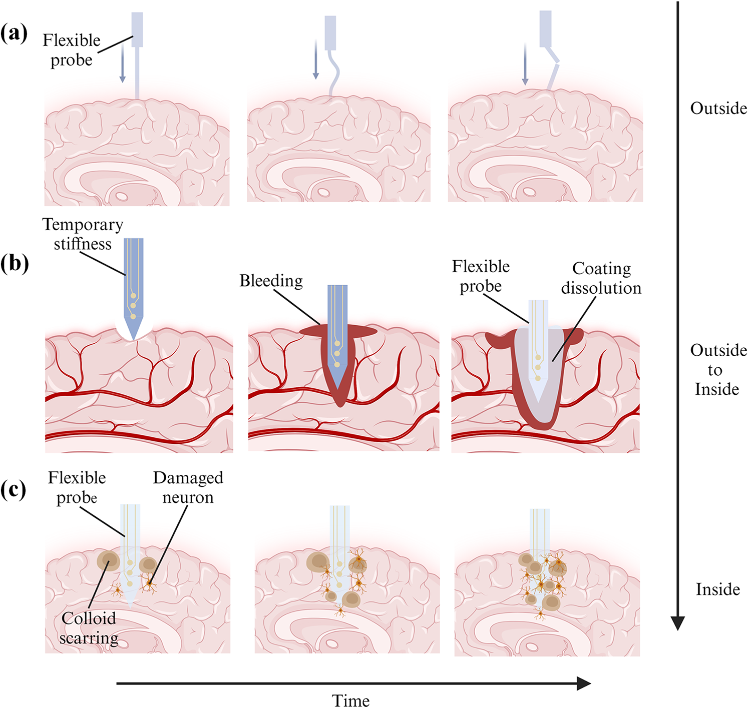
Figure 1: Process diagrams of buckling, insertion, and relative interaction with soft brain tissue of flexible neural probes. (a) Probe contacts with the brain from the outside, (b) Probe is being inserted into the brain from the outside, and (c) Probe is fully inserted into the brain for permanent implantation
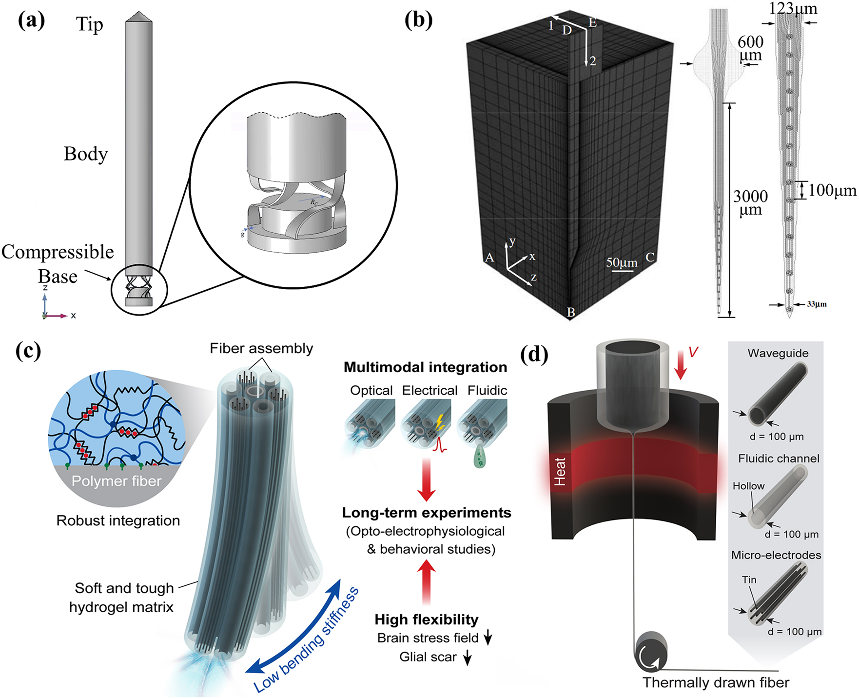
Figure 2: Mechanical modeling of neural probes. (a) A side view of the neural microprobe. Reproduced with permission of [22], Copyright of © 2023 Elsevier B.V., (b) A quarter-symmetry, 3D finite-element model (FEM) of the probe-brain tissue system with edge-biased seeding along the interface. Reproduced with permission of [23], © 2005 IOP Publishing Ltd., (c) A conceptual illustration of the hydrogel hybrid probe design, and (d) One-step direct polymerization of the hydrogel matrix within the fiber assembly. Reproduced with permission of [24], © The author(s) 2021, CC-BY-4.0
According to the previous literature on the mechanical simulation of neural probes, reducing the neural probe stiffness by three orders of magnitude can decrease the contact stress by 41.6% and strain by 39.1% [25,26]. It is due to the mismatch of the mechanical properties between the rigid probes and the soft brain [27–31]. The rigid implantable electrodes in the form of needles or probes can be penetrated the soft tissue with the aid of a pneumatic hammer or micromanipulator, such as the Utah array and Michigan probes [32–36]. However, most of these rigid neural probes are based on silicon (Elastic modulus E = 165 GPa) or tungsten (E = 400 GPa), with obvious mismatch with the soft brain tissue (E = 0.5–15 kPa) [37–40]. The excessive elastic modulus results in a high bending stiffness of the probes, causing intense stresses at the interface of the probe and the tissue. As a result, the rigid probes are usually accompanied by the obvious acute inflammatory response in the brain after implantation [41–45], which easily appears as glial scarring to encapsulate the rigid probes, leading to a significant decrease in the quality of neural signals [46,47]. As the mechanical modeling results show, although the insertion processes have an impact on acute vascular rupture and nerve injury [48–52], flexible probes cause less trauma than rigid for long-term implantation [53–57]. Thus, to provide ideas for the implantation of flexible probes and more long-term implantable probes, it is necessary to evaluate the acute and chronic trauma [58–62]. However, the trauma is very difficult to measure given its location deep in the brain [63], so mechanical modeling is an efficient way to evaluate the trauma.
However, most of the mechanical modeling of neural probes in the past has only addressed one of the processes of buckling, insertion, or relative interaction with soft brain tissue. No work has yet provided a comprehensive study of the mechanical simulation of the complete implantation of probes. In this paper, we will summarize the theoretical calculation methods and FEM results of flexible probes including the processes of buckling, insertion, and interaction with the brain. Besides, critical literature reviews are made for the mechanical modeling of flexible probes, and technical suggestions are provided for the realization of a more long-term, reliable, and safer in vivo neural interface.
In this section, we have reviewed the theoretical calculations of the flexible neural probes into three parts: (1) mechanical strength of probes, (2) tissue deformation due to probe insertion, and (3) interaction of flexible probes and brain tissue.
2.1 Mechanical Strength of Probes
The process of implanting a neural probe involves making an incision in the skin and performing a craniotomy, then puncturing the dura and exposing the leptomeninges [64]. During the insertion of the probe, it is crucial for the force used to surpass the force. The insertion force needs to be strong enough to penetrate the brain tissue or the leptomeninges successfully [65]. However, if the force exceeds the critical buckling force, the probe will bend [65,66]. As stated in the introduction, rigid probes have a significantly higher elastic modulus compared to the leptomeninges [67]. Table 1 provides material properties for different types of rigid and flexible probes. Flexibility scaling remains an unsolved problem. There is no universal definition of the term ‘flexible’, and Young’s modulus is widely used to evaluate the materials of neural implantations, as shown in Fig. 3 [67].
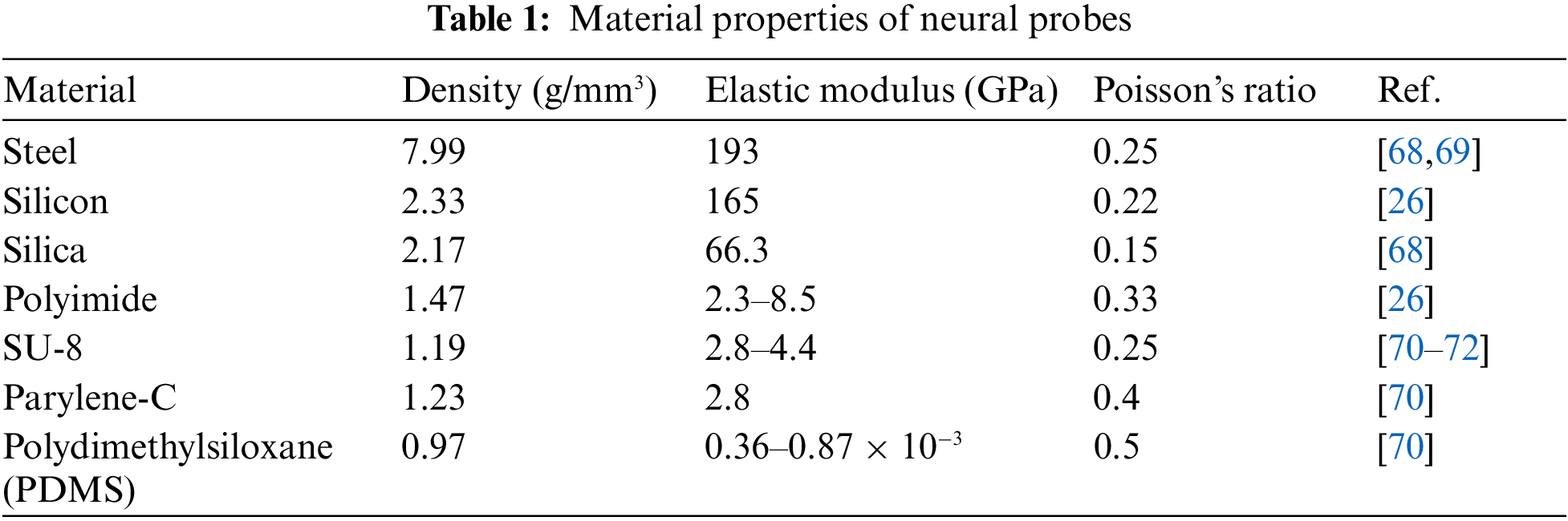
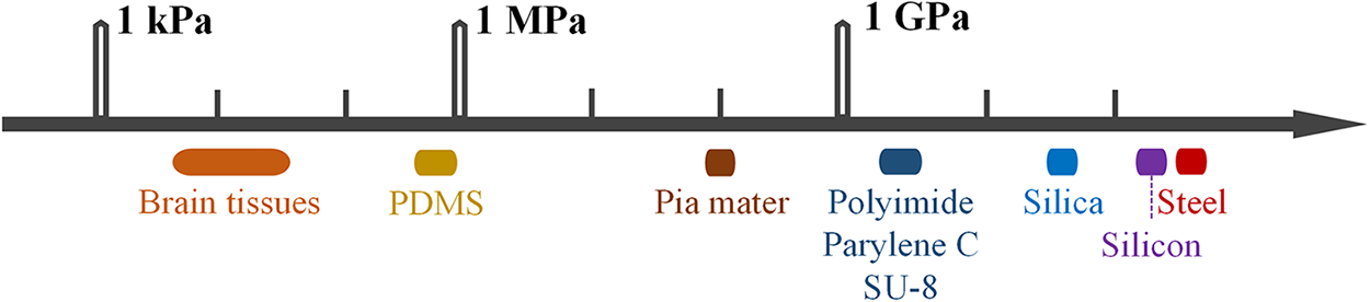
Figure 3: Differences in mechanical strength between brain tissue and nerve probes
This makes it easy to insert rigid probes into the brain. However, flexible probes have an elastic modulus similar to the leptomeninges. They are susceptible to buckling when they come into contact with leptomeninges. This makes it more difficult to penetrate the tissue [65,73]. Currently, to overcome the challenge, several strategies have been developed to assist with implanting flexible probes. Different insertion strategies are shown in Fig. 4.
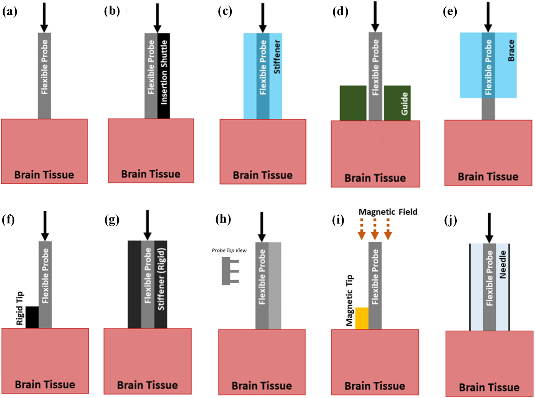
Figure 4: Insertion strategies of flexible probes. (a) Probe with no aid, (b) Probe with a shuttle, (c) Probe with a dissolvable stiffener, (d) Probe with a guide, (e) Probe with a dissolvable brace, (f) Probe with a stiff tip, (g) Probe with a stiffness-changing coating, (h) Probe with engineered cross section, (i) Probe with magnetic guidance, (j) Probe using injection. Reproduced with permission of [66], © 2021 IOP Publishing Ltd.
For instance, soluble support materials such as fibroin, polyethylene glycol (PEG), water gel, sodium alginate, etc., can provide temporary stiffness for flexible probes [41–44]. Metal can be inserted as a rigid skeleton layer [74–76]. SU-8 or microneedle handles can serve as removable shuttle bodies [77].
The critical buckling force can be used to characterize the mechanical strength of the probes and predict their suitability for successful insertion into brain tissue. During insertion, the insertion force must be lower than the critical buckling force to avoid probe bending. The theoretical calculation of the critical buckling force can be performed using Euler’s formula which is provided as
where Fbucking is the critical buckling force, E is the elastic modulus,
2.2 Tissue Deformation Due to Probe Insertion
When a probe is inserted into the soft brain tissue, it causes damage to the tissue alone [81]. These acute injuries trigger the body’s wound-healing response [82–86]. As shown in Fig. 5 [87], erythrocytes, platelets, and clotting factors are released and the complement cascade is activated. This leads to the aggregation of macrophages to remove the fluid or tissue residue. CD 68 is regularly used to identify activated microglia/macrophages. The number of CD 68+Cells increases after the implantation of a rigid probe. Also, cytokines and neurotoxic free radicals are released. This will reduce the probe’s performance. This collective immune response will create a region of high pressure and fluid build-up around the implantation area and persists for 6–8 d [88,89]. The acute injuries also influence the level of the chronic reaction [90–92]. The acute and chronic reactions can lead to increased contact impedance between the neural probes and brain tissue and increased signal-to-noise ratio, all of which are not conducive to long-term implantation of the neural probes [93–97].
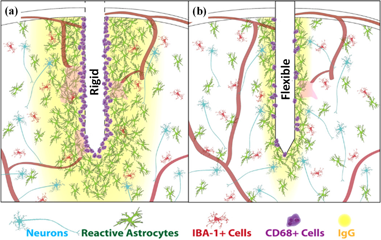
Figure 5: Comparison of tissue responses elicited by rigid and flexible probes. (a) Rigid probe, and (b) Flexible probe. Reproduced with permission of [87], © 2014 IOP Publishing Ltd.
Therefore, reducing the acute injuries of brain tissue caused by probes during insertion is important to improve the signal stability of neural probes for long-term implantation. Rigid probes can cause acute injury and damage to blood vessels during insertion [97]. Also, flexible probes cause huge acute injury, since they must be inserted by temporary stiffness to ensure that they will not buckling during insertion. So, both rigid and flexible probes can cause acute damage and injury to brain tissue during the insertion process [98].
To investigate the strain of brain tissue induced during probe insertion, a three-position finite element model can be constructed. This model consists of two components: the flexible or rigid probe and the surrounding brain tissue (shown in Fig. 6) [99]. There are meningeal layers around the brain. The meningeal layers are the meninges and the dura mater. Conversely, the brain-meningeal complex is wrapped in a rigid cranium, while cerebrospinal fluid fills the space between the meninges and the cranium. The lower extension of the brain is attached to the spinal cord by the brainstem. As a result, brain motion is restricted and border conditions are defined to fix the lower surface of the tissue in the simulation, thus avoiding large global displacements and allowing localized displacements around the implantation site [23]. This is accomplished by securing the edges ab, bc (Fig. 6a) and their respective mirror images (not shown) and therefore the bottom surface will not move or rotate. A boundary condition was defined at the back end of the probe such that it was displaced by 1 μm [100].
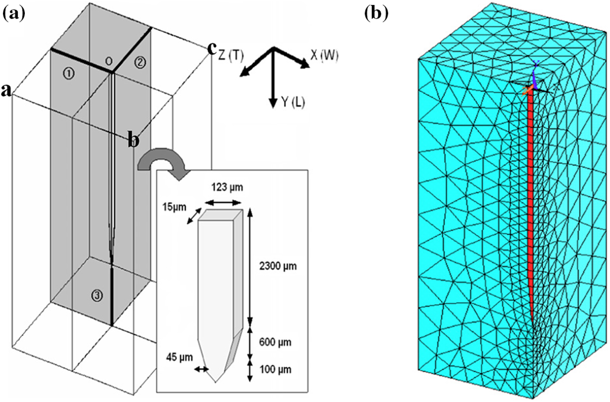
Figure 6: The electrode coordinate system and the mesh. (a) The electrode embedded in the brain. The X, Y and Z coordinate directions correspond to the width, longitudinal, and thickness directions, and (b) A quarter-symmetric grid in one quadrant of the model region is used to simulate vertical micromotion. Reproduced with permission of [99], © 2005 IOP Publishing Ltd.
Then, we can describe the brain strain distribution caused by the insertion process in terms of equivalent strain. The equivalent strain n εe is calculated by
where
Previous modeling using equivalent strain has shown that during insertion of the probes into the brain, the maximum strain in the brain tissue occurs at the tip of the probes [99,101]. Furthermore, regarding fluid displacement and vascular rupture, faster insertion speed (2000 μm/s) appears to result in minimal fluid displacement through cerebral arteries, while slower insertion speed (500 and 125 μm/s) frequently results in displacement and rupture downstream of these vessels [102]. Curves of load and displacement can also be established to represent the change in force required to insert the probes into the brain and to predict the degree of damage to the brain tissue [40].
2.3 Interaction of Flexible Probes and Brain Tissue
Because of the natural movement of the human body, such as breathing and heartbeat, there is relative interaction between the neural probes and the brain tissue [103]. Neural probes are susceptible to damage to surrounding nerve cells due to micromotion of the probes, leading to a chronic inflammatory response or necrosis of nearby neurons [104]. For chronically implanted neural probes, necrotic neurons can produce gelatinous scarring on the surface of the probes, which increases contact resistance and deteriorates the signal [46,97,105–107] To simulate different levels of mechanical coupling between the inserted probe and the brain, the friction coefficients between the two materials can be different in the exposure model. Therefore, an attachment model or a combination of adhesion and friction can be used to simulate the physical interaction between the probe and the brain tissue [99].
In order to further quantify the magnitude of tissue damage induced by the micromotion of the probes, several studies have employed a linear viscoelastic material model to investigate the effect of the micromotion of the probes [99,108–110]. The shear behavior of the linear viscoelastic model was characterized as a function of time by
where
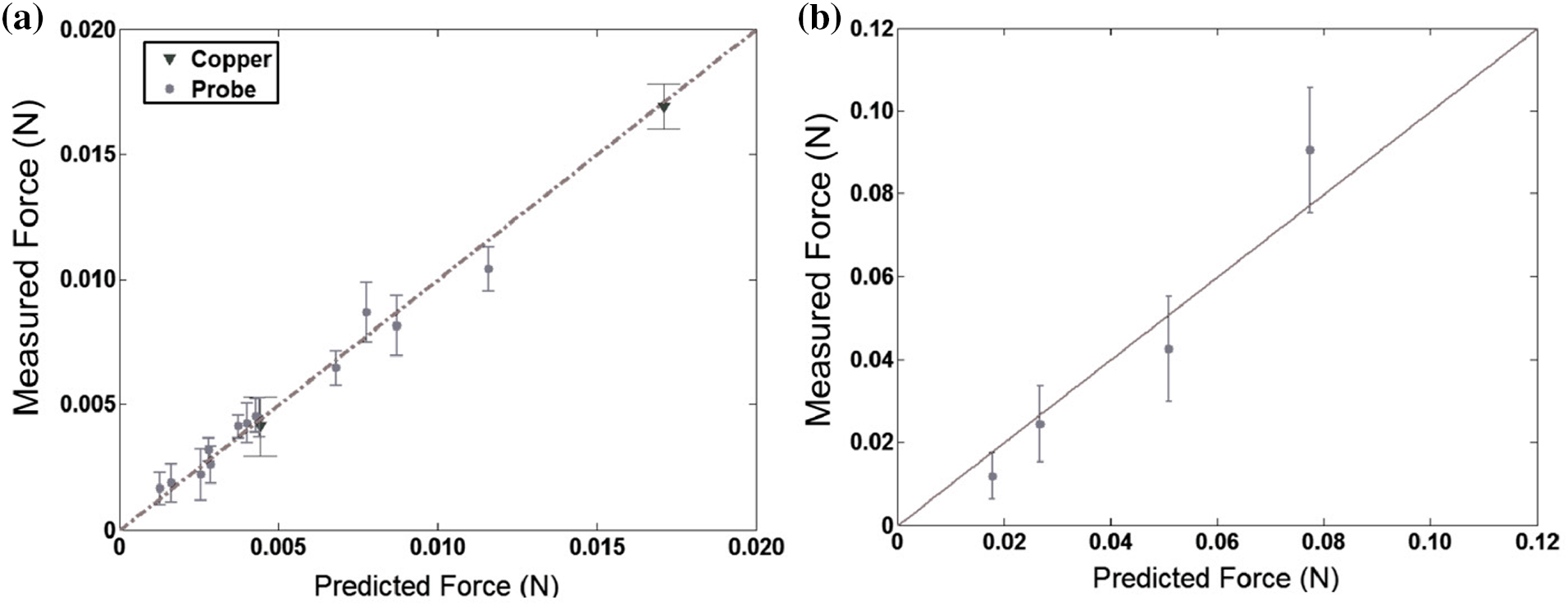
Figure 7: Comparing the experiment results to model prediction. (a) Probe insertion into E18 embryonic chick brain tissue (
However, the use of the linear viscoelastic model presupposes the assumption that the probe micromotion deformations are small. However, it has been reported that anesthetized rats can produce surface brain micromotion up to 25 µm during respiration, which is inconsistent with the assumption that probe micromotion deformations are small [111,112]. Therefore, Hamzavi et al. [76] used a nonlinear hyperelastic model to perform a finite element analysis of the relative micromotion of the probes in comparison with a linear viscoelastic model. The maximum principal strain near the tip of the probes derived using the nonlinear model was found to be significantly higher than the linear model by 58%. The nonlinear model reported by Taylor and Miller also improved accuracy by 2% relative to the linear model [113,114]. Therefore, the linear viscoelastic model assuming small deformations of brain tissue may underestimate the actual stress and strain values.
The nonlinear hyperelastic model does not take into account the time-dependent behavior of the brain tissue and uses the polynomial strain energy density function as
where
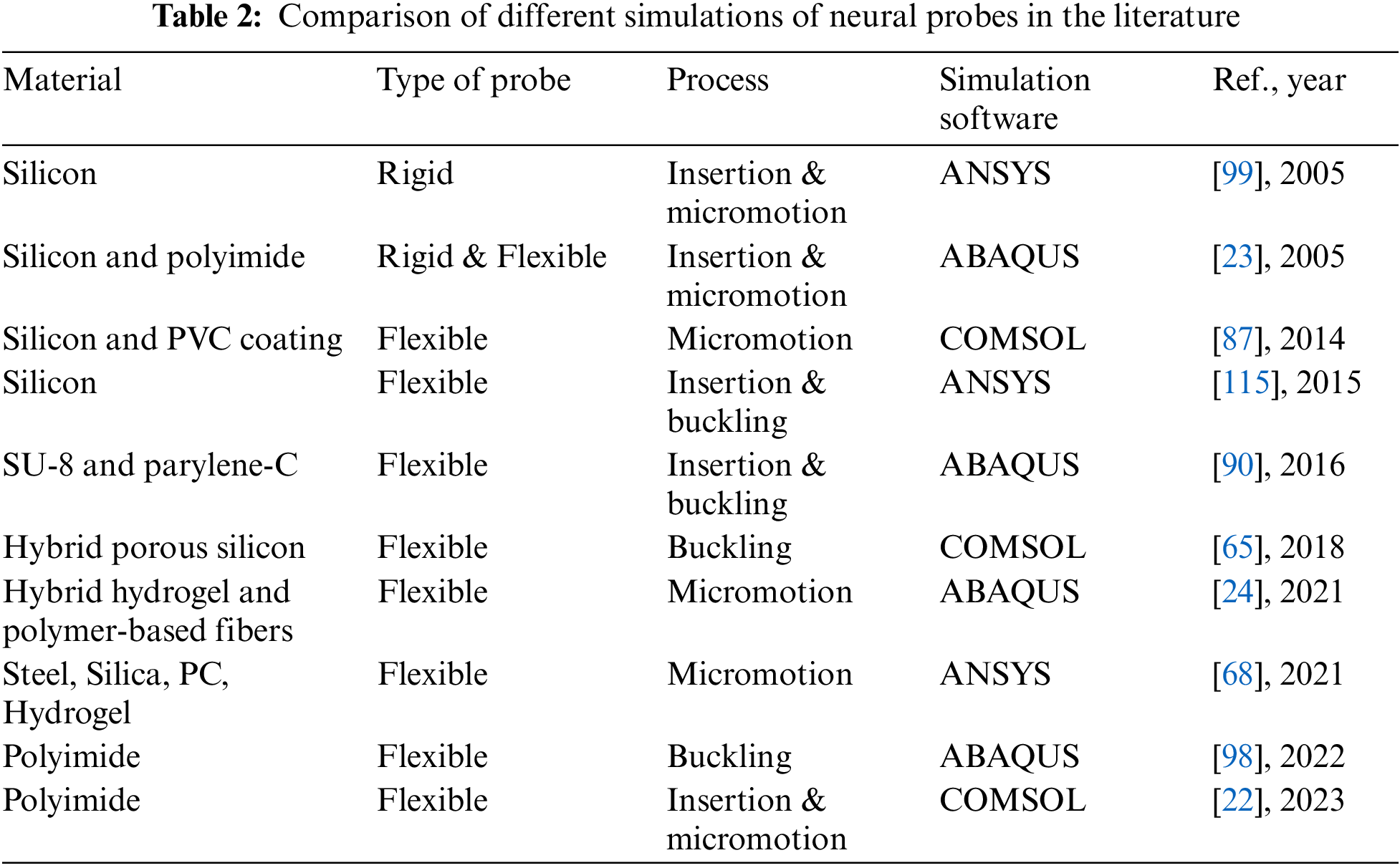
Computational modeling is a highly effective approach to assessing the impact of various factors on flexible probes’ mechanical properties. FEM has been applied to neural probes, specifically to comprehend how the probes behave and influence the stress at the probe-tissue interface during the insertion process. In addition, other research groups have focused on simulating mechanical trauma to the brain after insertion to design probes that cause less tissue trauma [90]. Results for the flexion, insertion, and micromotion processes of neural probes are shown in Table 2.
We can see the mechanical simulation of buckling, insertion, and micromotion processes for flexible probes has been under development for the past few years. The simulations can provide more ideas for better designs to minimize acute and chronic injuries. In this section, we will review the mechanical simulations for buckling of flexible probes, brain tissue deformations, and relative interaction between flexible probes and the brain and provide ideas for designing less invasive flexible probes.
3.1 Simulation of the Buckling Process
According to Eq. (1), the critical flexion force of flexible probes is positively correlated with the modulus of elasticity, and once the stress at implantation exceeds the critical flexion force, the probes may be destroyed. To strengthen the critical flexural force of the flexible probes, Guo et al. [98] designed a silicon shuttle, in which the flexible probe is pasted onto the silicon shuttle by PEG, thus increasing the stiffness of the flexible probes. To enhance the mechanical properties of the silicon shuttle, the reinforcement is set on the back of the silicon shuttle. The mechanical simulation is carried out by ABAQUS for the silicon shuttle without and with reinforcement, respectively. Figs. 8a and 8b show the stress distribution of the two kinds of silicon shuttles under the same compression distance. The maximum stresses with and without reinforcement are 399 and 312 MPa, respectively. This indicates that the reinforcement avoids the unstable bending of the silicon shuttle during implantation. It also provides a concentrated force for the silicon shuttle, which makes it easier to implant into the brain.
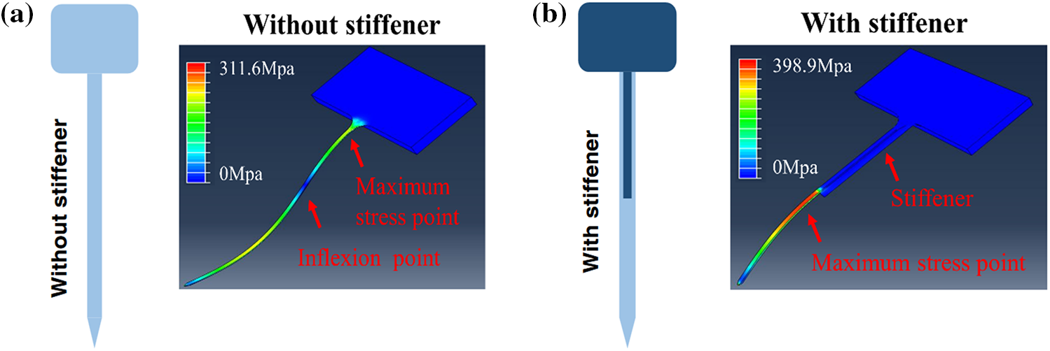
Figure 8: Mechanical simulation of the flexible probe without and with the stiff shuttle. (a) Equivalent strain distribution of the flexible polyimide probe without a stiffener, and (b) Equivalent strain distribution of the flexible polyimide probe with a stiffener [98]. Reproduced with permission of [98], © 2022 by the authors, CC-BY-4.0
Another way to change the elastic modulus of the flexible probes is by using different dissolvable stiffeners [116]. Zhou et al. [117] reported a hybrid probe (Silk-Optrode) consisting of a silk protein optical fiber and multiple flexible microelectrode arrays. Based on the strain-stress curves of the silk fiber in the dehydrated and undehydrated states, it can be found that the modulus of elasticity of the silk fiber is 38.7 MPa before dehydration, while it becomes 3.57 MPa after dehydration. Besides, the dehydrating properties of the material can be utilized to insert the flexible probes into the brain tissue after it has been dehydrated. This makes the probes rigid before implantation and soft after implantation.
On the other hand, it can be seen that the critical buckling force is proportional to
Yagi et al. [115] proposed a way to provide temporary stiffness by embedding a hard coating in the base of a flexible probe and analyzed the approach with simulation modeling. The coating dissolves on contact with biological tissue (Fig. 9c). This method reduces the effective length of the flexible probe and thus increases the elastic modulus of the probe. The results showed that the stiffness of the silicon needle increased from 2.30 to 3.59 N/m after embedding the silk film holder, a 56% increase in stiffness. This suggests that the bending of the probes is mainly related to the length of the needle segment exposed by the silk film holder (Figs. 9a, 9b). Arafat et al. [118] proposed a mechanism for guided insertion to fix the guide of the flexible electrode above the brain so that the electrode leaks only the tip. The guide device decreases the effective length of the electrode and increases the elastic modulus for smooth insertion of the probes into the brain tissue.
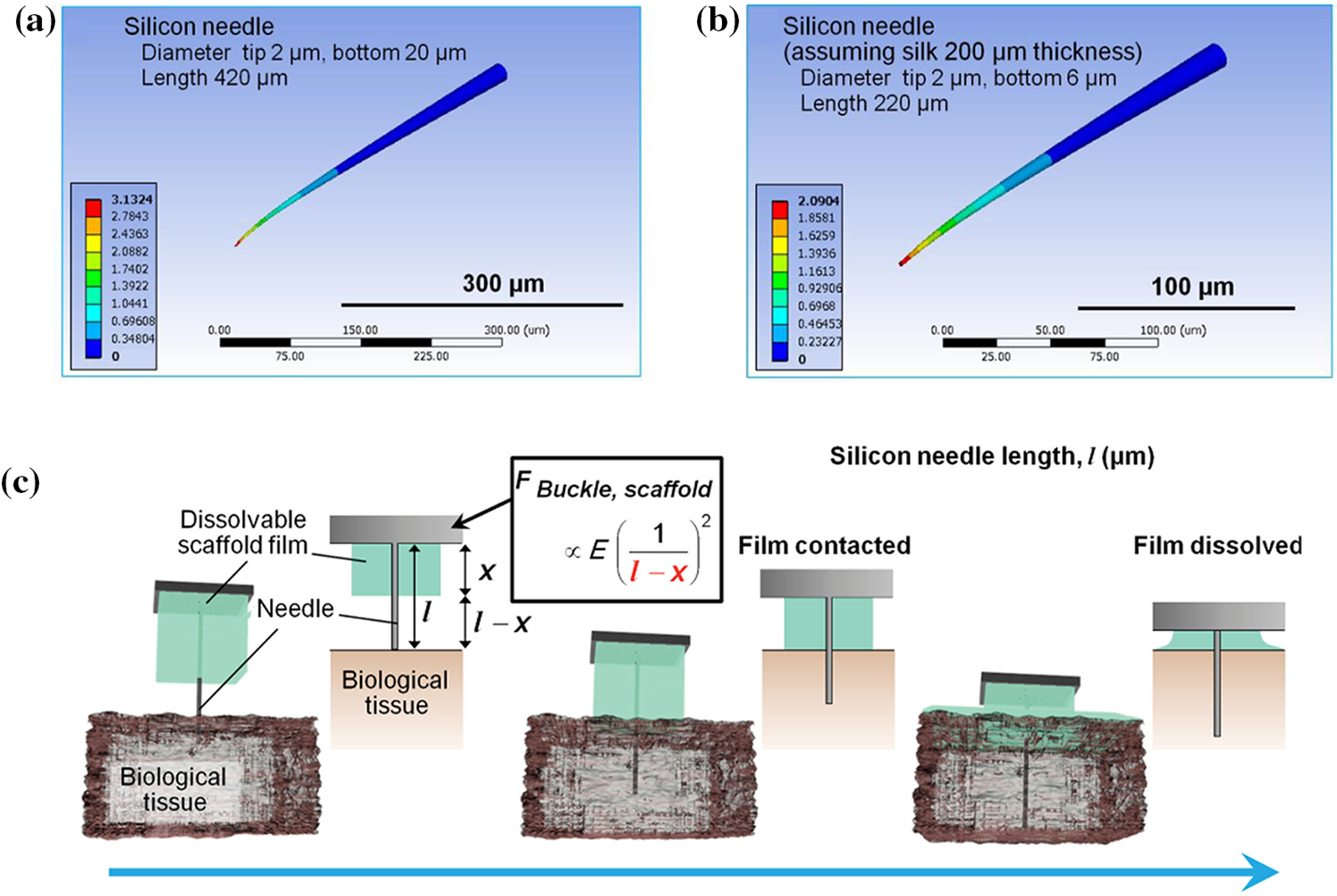
Figure 9: Impact of effective length for probe. (a) Simulation of silicon needle, with tip and bottom diameters of 2 and 20 μm, respectively, and needle length of 420 μm, (b) Simulation of silicon needle with silk film holder (thickness is 200 μm), and (c) Procedure for penetration of a high-aspect-ratio flexible microneedle using a dissolvable base scaffold. Reproduced with permission of [115], © 2015 WILEY-VCH Verlag GmbH & Co. KGaA, Weinheim
The approaches reduce the effective length of the flexible probe, which can in turn increase the critical flexion force of the probe. This allows the probe to be inserted into the brain without the need for implantable aids or sclerotherapy penetration. At the same time, rotation of the probe prevents the dura mater from adhering to the probe and allows stable implantation of the probe to be maintained. Based on both guided insertion and rotation strategies, they succeeded in implanting the 25 μm probe into the rat brain at a depth of 10 mm without bending it. In addition, to avoid flexion during the implantation of flexible probes, a method of injecting mesh electrodes with a large bore syringe has recently been reported, whereby flexible electrodes are implanted into the brain by injection [119–121]. This approach allows seamless integration of mesh electrodes with brain tissue. The mesh electrodes retain their structural integrity after injection through a smaller diameter needle. The memory properties of some materials can be utilized to minimize the size of the electrodes and implanted devices at the time of implantation. After implantation, the electrode unfolds within the brain due to its memory properties.
3.2 Simulation of Brain Tissue Deformations
Due to the easy buckling property of the flexible probe, the insertion of the flexible probe must be aided by a rigid auxiliary tool. So, the insertion of flexible neural probes is similar to the rigid probes. It produces acute trauma to the brain, and these acute traumas can transform into chronic traumas over the long term of implantation and affect signal recording [122]. To quantify and minimize the trauma of the implantation process, we will summarize the simulation of tissue deformation caused by the insertion of flexible probes into brain tissues. And provide more ideas for the implantation of flexible probes in terms of shapes, implantation speeds, and assisting strategies.
The degree of damage caused when the probes are inserted into the brain tissue is closely related to the geometry of the implant, such as tip angle, cross-sectional area, modulus of elasticity, and overall configuration [90,102,123]. Kim et al. [68] performed finite element modeling of tissue deformation to analyze the effect of flexible and rigid probes cross-sectional shape on brain tissue damage. The model uses different implantation of probes with different cross-sectional shapes, as well as probes with the same cross-sectional shape but different aspect ratios, as shown in Fig. 10.
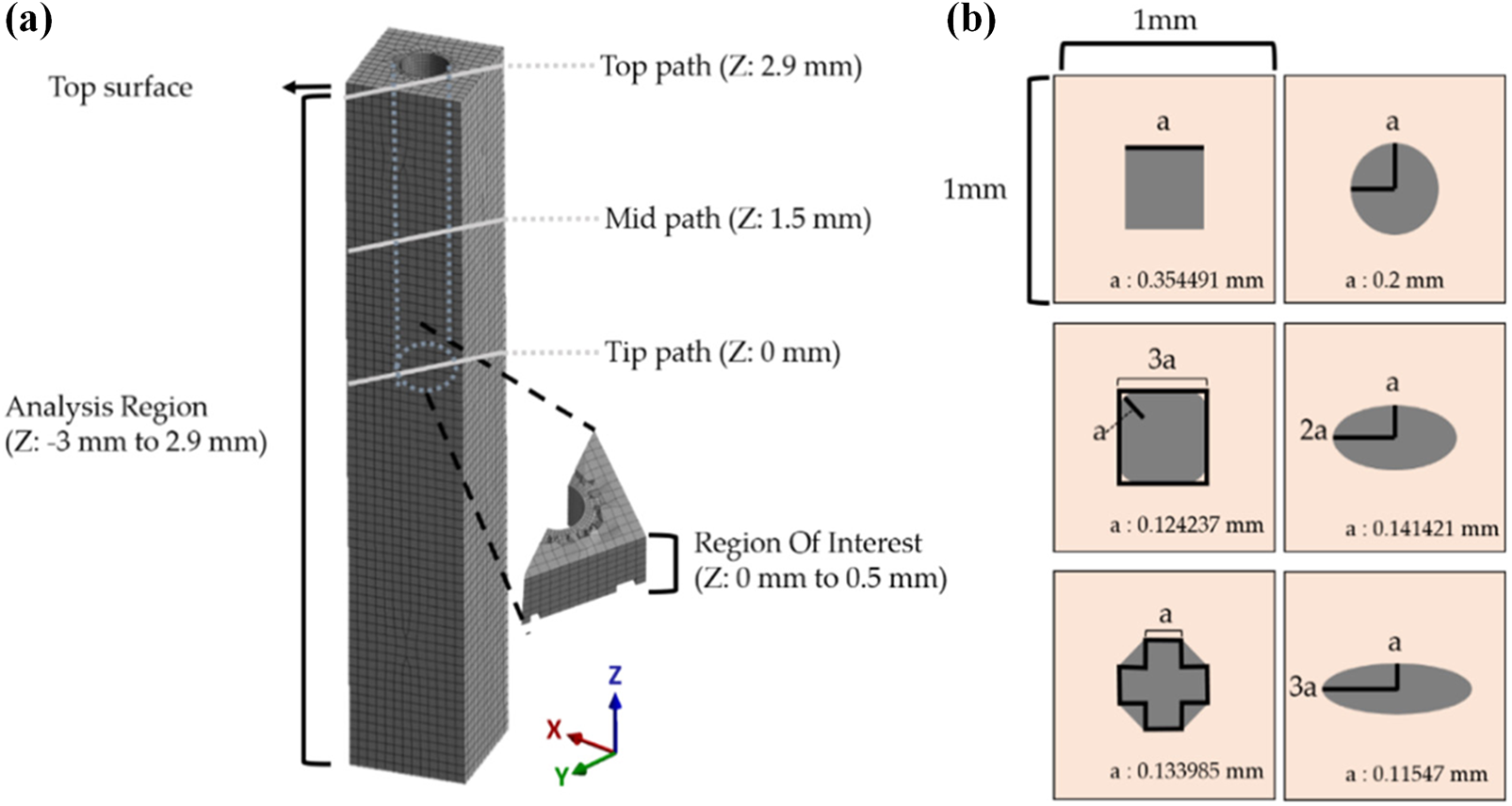
Figure 10: Analysis region and various cross-sectional shapes of the probe. (a) The maximum and averaged equivalent strain vs. time were investigated in the ROI (500 μm from the tip), and (b) Various cross-sections of the probe. Reproduced with permission of [68], © 2021 by the authors, CC-BY-4.0
The results show that larger aspect ratios lead to an increase in critical volume, with the volume of the critical region increasing more than 5 times when the cross-sectional aspect ratio is 3 times larger (the larger the critical region, the greater the trauma to the brain tissue). Besides, when the aspect ratio was certain, the peak value of the maximum strain of the brain tissue decreased in the order of octagonal, square, rounded square, and ellipse, which were 0.1385, 0.1236, 0.1226, and 0.1157 mm3, respectively. As a result, rounded interface shapes are beneficial in reducing brain tissue trauma, while sharp shapes with angular corners increase trauma. The design of the needle tip needs to be considered while ensuring that the implanted device reduces the sharp shape. A rounded tip may result in the implanted device not being inserted into the brain tissue or causing greater trauma.
Another factor that affects the extent of brain tissue damage is the speed of probe insertion. Neural probes designed for extracellular recording of brain electrical activity are traditionally implanted with an insertion speed between 1 μm/s and 1 mm/s into the brain tissue [34]. At high speed of insertion, the brain tissue and blood vessels at the tip of the needle can produce greater damage. At low insertion speed, the damage at the needle tip is reduced [124]. Casanova et al. [125] proved that faster needle insertion produced less friction stress and greater track damage (Fig. 11b). Hydrogels exhibited trends opposite to those of brain tissue. Lee et al. [126] used different speeds to implant silicone needles into the brain and found that the insertion force measured at the point of insertion was less when inserted at a higher speed than when inserted at a lower speed. And lower insertion speed caused significant bending of the probes (Fig. 11c). Zhang et al. [127] found that an increase in insertion speed will increase the max insertion force (Fig. 11a). The increase of the max insertion force made the deformation of brain tissue and the damage to blood vessels more serious.
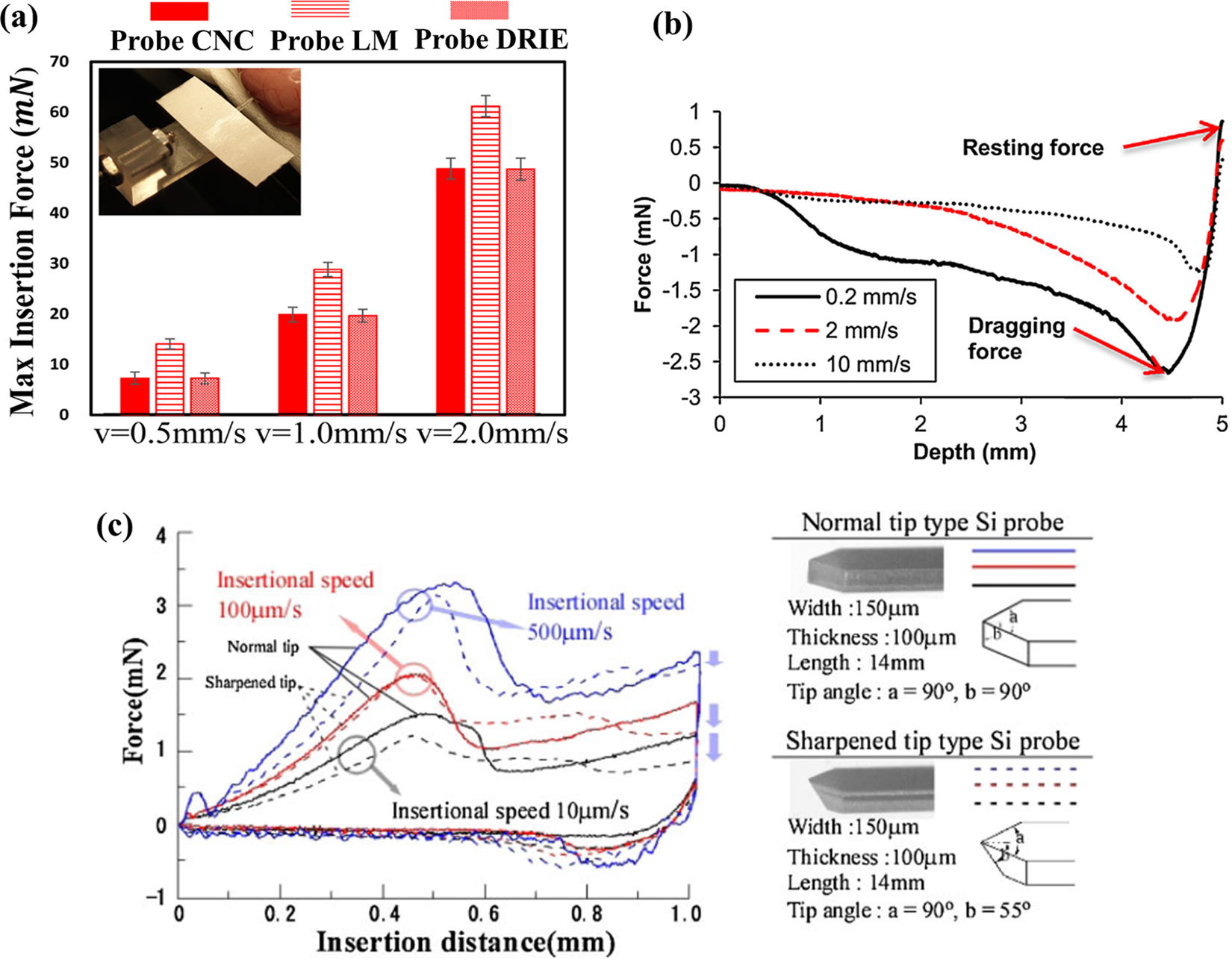
Figure 11: The impact of insertion speed on the insertion force. (a) Fmax induced by Probe CNC, Probe LM, Probe DRIE in Phantom Rat Cerebrum. Reproduced with permission of [127], © The author(s), under exclusive licence to Springer Science+Business Media, LLC part of Springer Nature 2021, (b) Needle retraction force vs. depth for varying insertion speeds in brain tissue. Reproduced with permission of [125], © 2014 Elsevier B.V., and (c) Comparison of insertion characteristics for the Si neural probes with normal and sharpened tips. Reproduced with permission of [126], © 2013 The Japan Society of Applied Physics
So, the higher inserting speed decreases the insertion force, while the lower insertion speed causes less tissue damage. It is possible to combine the advantages of high-speed and low-speed insertion, using a higher speed at the beginning of insertion and a lower speed after insertion of the tissue, to avoid the bending phenomenon of the probes and at the same time to reduce the damage to the brain tissue.
3.2.3 Friction Property of Probes and Tissues
In particular, the frictional stress at the needle-tissue surface (the product of the prestress and the friction coefficient) is related to the tissue contact volume with the indentations [64]. Zhu et al. [128] performed a finite element modeling of the strain in the brain tissue when the neural probes were exposed to longitudinal loads of 0, 0.1, 0.5, and 5 (near bonding). They concluded that the equivalent strain in the brain increased with increasing friction coefficient. In another study, Andrei et al. [129] showed that covering the probe with Parylene-C will reduce the friction with brain tissue. Reducing the coefficient of friction between the implanted flexible probe device and the brain tissue can reduce the strain and trauma on the brain tissue caused by the implantation process. Therefore, a neuro-integrative coating of the probe is recommended to increase friction between the microelectrode and the brain and to reduce chronic tissue damage.
3.3 Simulation of Relative Interaction with Soft Brain Tissue
The respiratory process of anesthetized rats can cause pulsations of 2–30 microns, and this apparent micromotion can influence the long-term implantation of flexible probes. Past studies have demonstrated that the interaction of chronically implanted probes with the surrounding tissue may lead to chronic inflammation or necrosis of nearby neurons [104]. Quantifying the interaction of the flexible probes with the brain tissue is important for long-term neural recordings. In the following, we will summarize the results of the finite element simulation of the probe-brain interaction and analyze the reasons affecting the stability of the probes for long-term implantation.
One of the main reasons for the degradation of signal quality in long-term implantation of neural probes is the large difference in stiffness between the probes and the brain tissue [129,54–57]. Polanco et al. showed that when micromotion-induced pulses are applied, reducing the neuron probe stiffness by three orders of magnitude leads to a 41.6% reduction in stress and a 39.1% reduction in strain [26].
Subbaroyan et al. used finite elements to develop a 3D finite element model of the probe-brain tissue microenvironment and analyzed the effect of the stiffness of the chronically implanted probes on the brain tissue interface as shown in Fig. 12 [23]. As can be seen in Fig. 12b, a polyimide-based flexible probe (E = 200 kPa) causes significantly lower brain tissue strain (measured with length constants) in the middle of the probe as well as at the tip of the needle compared to a silicon probe (E = 200 GPa) (Fig. 12a). This suggested that minimizing the stiffness of the probes will greatly reduce brain tissue deformation, thus providing the possibility of longer-term implantation of flexible probes. This is probably because of the flexible probe’s ability to bend freely. It will move freely at the surface of the brain, which increases the trauma to the surface of the brain.
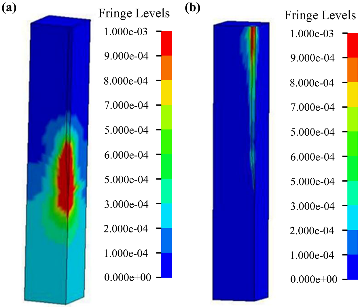
Figure 12: Strain distribution of the brain using a micromotion displacement of 4 µm and interfaced with a (a) 200 GPa silicon probe and (b) 200 kPa flexible probe. Reproduced with permission of [23], © 2005 IOP Publishing Ltd.
In contrast, most relative interaction with soft brain tissue simulations uses a linear viscoelastic model. This model is based on the theory of small deformations, which means the deformation of the brain tissue is assumed to be very small. For the accuracy of the linear model, Hamzavi et al. [76] proposed the use of a nonlinear model to simulate the interaction of the probe with the brain. The results showed that the strain around the tip of the needle exceeded the generally accepted linear strain range, and the use of a nonlinear model improved the accuracy of the strain simulation. Zhou et al. [117] reported a hybrid probe combining silk and flexible microelectrode arrays. They developed a FEM model to simulate the micromotion process of the flexible probe (Fig. 13a), as shown in The relative displacement and maximum von Mises results are shown in Figs. 13b, 13c. The results show that only the silk optical fiber demonstrates an agreeable mechanical match to the brain tissue.
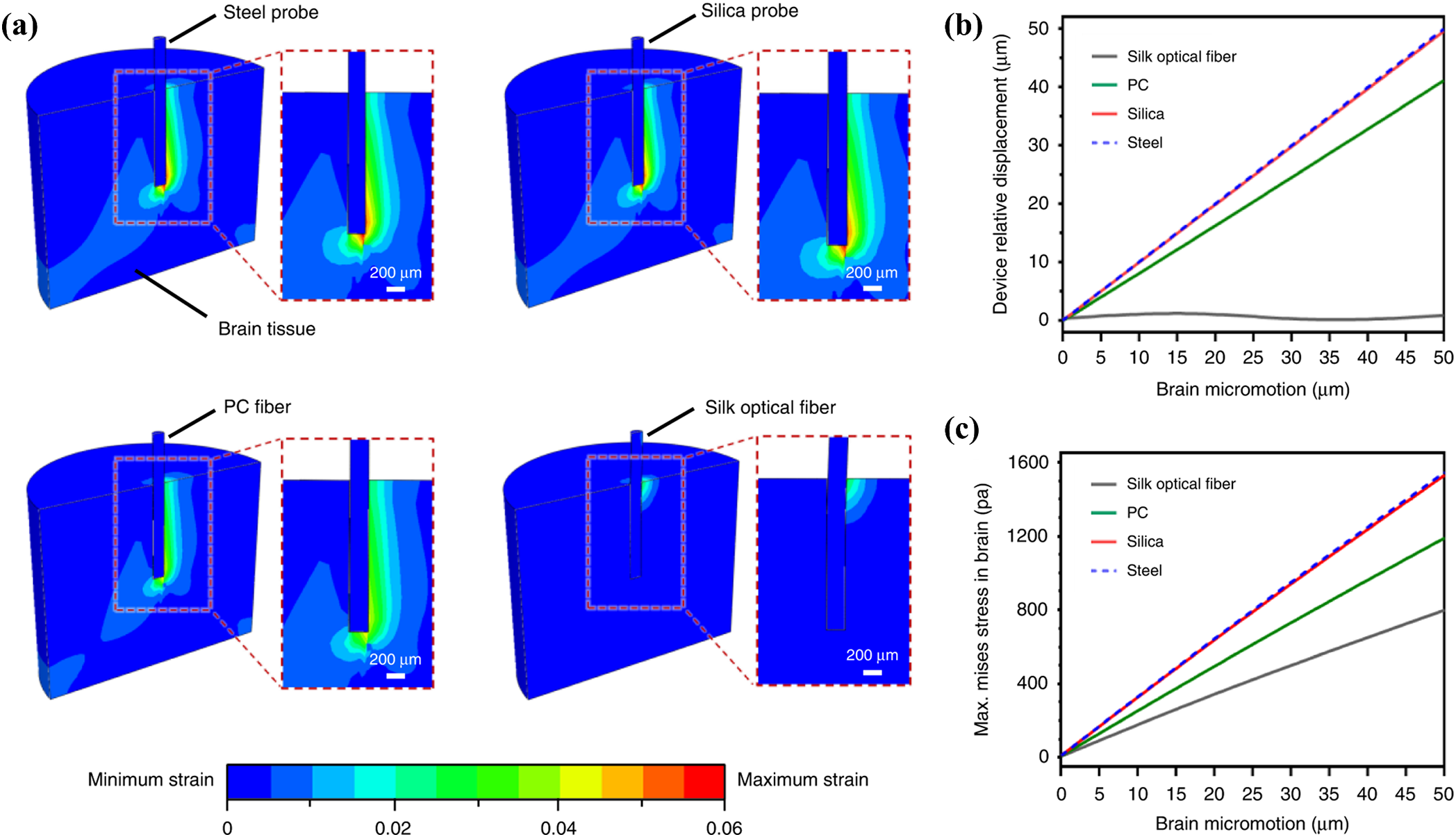
Figure 13: Micromotion of different flexible probes. (a) Maximum strain fields of the brain tissue steel, silica, PC fibers, and flexible silk optical fibers implants (during 50
3.3.2 Coefficient of Friction between the Brain and Probe
The coefficient of friction between the probe and brain tissue was 0.6 in the early stages of the formation of a glial scar at the probe implantation site, and the coefficient of friction of a flexible probe with a polymer coating ranged from 0.2 to 0.3, while the coefficient of friction within the brain tissue without the implantation of the probe ranged from 0.1 to 0.2 [26,130]. Therefore, it is important to examine the effect of coupling the flexible probe to the brain tissue due to friction.
Michael et al. used a nonlinear finite element model to model the interaction between a chronically implanted flexible probe and the brain [130]. The modeling results show that the equivalent strain of the brain decreases with increasing friction coefficient (Fig. 14a), and the relative motion of the brain and the probe shows the same pattern (Fig. 14b). Therefore, coatings can be used to increase the adhesion of the flexible probe to the brain tissue to reduce the interaction caused by the probe and the brain tissue.
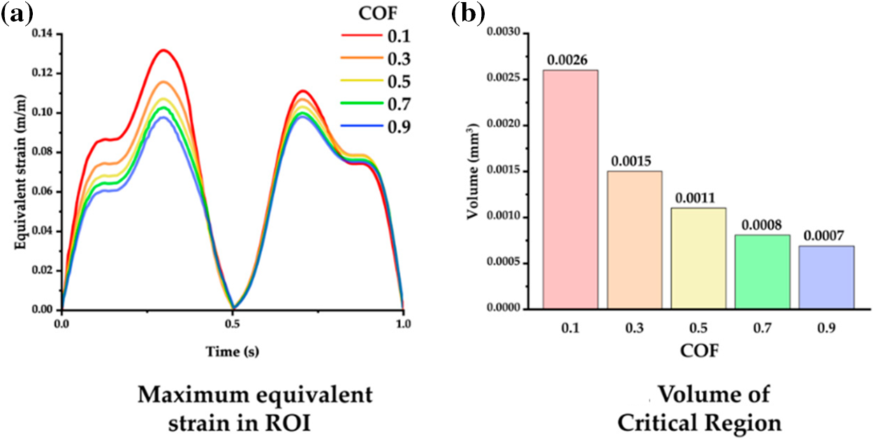
Figure 14: Interaction of probes with different friction coefficients and the brain (a) Relationship between equivalent strain and coefficient of friction, and (b) Relationship between volume of the critical region and coefficient of friction. Reproduced with permission of [130], © 2012 SPIE
However, reducing the coefficient of friction between the implanted device and the brain reduces the brain trauma induced by the implantation process, as described in 3.2.3, contrary to the conclusions of the micromotion process. The design of flexible neural probes needs to seek the most appropriate friction coefficient to balance acute and chronic trauma. When implanting a flexible probe, the coefficient of friction between the probe and the brain is reduced to minimize brain trauma. When the probe is fully implanted in the brain tissue, the surface of the probe needs to be made as smooth as possible to reduce friction with the brain tissue [131]. This prevents excessive friction from leading to chronic damage caused by long-term implantation of the probe.
4 Conclusion and Future Prospects
This review summarizes the theoretical calculations of the critical buckling, insertion, and interaction processes of the flexible probe with brain tissue, and analyzes the corresponding mechanical simulation results. Firstly, the buckling process of the probe is calculated using Euler’s formula, which describes the mechanical properties of the probe when contacted with the brain tissue. Secondly, the equivalent strain is used to describe the deformation of the brain tissue caused by the probe when it is inserted into the brain. Thirdly, a linear viscoelastic or a nonlinear hyperelastic model is adopted for the interaction between the probe and the brain during the long term of implantation. Besides, by the mechanical simulation of these three key processes, suggestions can be provided for the probe design and operation to minimize acute and chronic injuries. For acute implantation, the tissue damage can be reduced by adjusting the penetrating speed, the friction coefficient between the probe and the brain tissue, as well as the cross-sectional area of the probe. For chronic implantation, softer probes can be applied with an increased coefficient of friction between the probe and the brain to avoid relative micro-motion.
However, there are still shortcomings in the current mechanical simulation of flexible probes. Firstly, most simulations use linear models for small deformations. The brain tissue micro-movements caused by breathing and heartbeat are inconsistent with the assumption of small deformations for simulation analysis. The simulation method needs to be improved for larger deformations, such as using a nonlinear model. Secondly, simulation results do not provide guidance or optimization for experiments. In the past, most simulations were done to match and validate the experiment results. However, the simulation results can also be taken as helper methods to reduce implantation trauma and mitigate long-term damage. Therefore, in the future, the shape and material of the probe can be optimized according to the simulation results. Thirdly, data sharing and standardization are insufficient. From past simulation studies, differences can be found in the computational and modeling methods used by different teams. Different computational methods and models can cause errors in different aspects of the actual situation. Therefore, a unified simulation modeling method is needed to minimize the error.
Overall, the main issues for flexible probes in mechanical modeling are the difficulty of implantation and the difficulty of performing long-lasting signal recording. In the future, the difficulty of implantation should be addressed first and foremost. An implantation protocol is needed that allows for minimally invasive and accurate implantation of the flexible probe in the desired location. For example, flexible probes can be designed and unfolded into a predetermined shape in response to body temperature after penetrating the brain, avoiding additional damage caused by mechanical penetration force. For modeling, we can use the method of deep learning. Based on the material properties and shape of the flexible probe, it is possible to establish an explicit prediction method of the insertion force and depth during the insertion of a flexible probe [131–133]. Through reverse analysis [133–137], the process of probe insertion can be immediately analyzed, providing options for the insertion strategy. Furthermore, the other effects can be taken into account, such as size effect [138], residual stress and strain [139–142], and rate dependency [143–146]. To realize long-term coexistence, softer materials are needed to alleviate the immune response in brain tissue and adapt to the micro-motion from any cause. Besides, the friction coefficient between the probes should be taken into consideration. The friction will highly influence the micromotion between the brain and the flexible probe. Mechanical modeling will guide the structural design, material selection, and implantation methods of implantable flexible probes more scientifically and effectively to pave the way for advanced brain science research tools and disease diagnosis and treatment.
Acknowledgement: None.
Funding Statement: This work acknowledges the support received from the National Natural Science Foundation of China (Grant Nos. 62204204 and 52175148), Science and Technology Innovation 2030-Major Project (Grant No. 2022ZD0208601), Shanghai Sailing Program (Grant No. 21YF1451000), Presidential Foundation of CAEP (Grant No. YZJJZQ2022001). We acknowledge the technical support from Neuracle Medical Technology (Shanghai) Co., Ltd.
Author Contributions: The authors confirm contribution to the paper as follows: study conception and design: Xiaoli You, Ruiyu Bai, Bowen Ji, Xu Long and Qiang Shen; data collection: Kai Xue, Honglong Chang, Zimo Zhang and Minghao Wang; analysis and interpretation of results: Xuanqi Wang, Jiahao Wang, Jinku Guo, Xiaoli You and Ruiyu Bai; draft manuscript preparation: Xiaoli You and Ruiyu Bai. All authors reviewed the results and approved the final version of the manuscript.
Availability of Data and Materials: The data that support the findings of this study are available from the corresponding authors upon reasonable request.
Conflicts of Interest: The authors declare that they have no conflicts of interest to report regarding the present study.
References
1. Logothetis NK, Augath M, Murayama Y, Rauch A, Sultan F, Goense J, et al. The effects of electrical microstimulation on cortical signal propagation. Nat Neurosci. 2010;13(10):1283–91. [Google Scholar]
2. Vázquez-Guardado A, Yang YY, Bandodkar AJ, Rogers JA. Recent advances in neurotechnologies with broad potential for neuroscience research. Nat Neurosci. 2020;23(12):1522–36. [Google Scholar]
3. Willett FR, Avansino DT, Hochberg LR, Henderson JM, Shenoy KV. High-performance brain-to-text communication via handwriting. Nat. 2021;593(7858):249–54. doi:10.1038/s41586-021-03506-2. [Google Scholar] [PubMed] [CrossRef]
4. Ju J, Feleke AG, Luo L, Fan X. Recognition of drivers’ hard and soft braking intentions based on hybrid brain-computer interfaces. Cyborg Bionic Syst. 2022. [Google Scholar]
5. Zhao S, Tang X, Tian W, Partarrieu S, Liu R, Shen H, et al. Tracking neural activity from the same cells during the entire adult life of mice. Nat Neurosci. 2023;26(4):696–710. doi:10.1038/s41593-023-01267-x [Google Scholar] [PubMed] [CrossRef]
6. Ganzer PD, Colachis SCt, Schwemmer MA, Friedenberg DA, Dunlap CF, Swiftney CE, et al. Restoring the sense of touch using a sensorimotor demultiplexing neural interface. Cell. 2020;181(4):763–73. [Google Scholar]
7. Lorach H, Galvez A, Spagnolo V, Martel F, Karakas S, Intering N, et al. Walking naturally after spinal cord injury using a brain-spine interface. Nat. 2023;618(7963):126–33. doi:10.1038/s41586-023-06094-5. [Google Scholar] [PubMed] [CrossRef]
8. Zhou L, Wu Z, Sun M, Park J, Han M, Wang M, et al. Flexible, ultrathin bioelectronic materials and devices for chronically stable neural interfaces. Brain-X. 2023;1(4):e47. doi:10.1002/brx2.v1.4. [Google Scholar] [CrossRef]
9. Donoghue JP. Bridging the brain to the world: a perspective on neural interface systems. Neuron. 2008;60(3):511–21. doi:10.1016/j.neuron.2008.10.037 [Google Scholar] [PubMed] [CrossRef]
10. Chen G, Cheng L, Shao R, Wang Q, Wang S. A review of device-free indoor positioning for home-based care of the aged: techniques and technologies. Comp Model Eng. 2023;135(3):1901–40. doi:10.32604/cmes.2023.024901. [Google Scholar] [CrossRef]
11. Birbaumer N. Breaking the silence: brain-computer interfaces (BCI) for communication and motor control. Psychophysiol. 2006;43(6):517–32. doi:10.1111/psyp.2006.43.issue-6. [Google Scholar] [CrossRef]
12. Brumberg JS, Nieto-Castanon A, Kennedy PR, Guenther FH. Brain-computer interfaces for speech communication. Speech Commun. 2010;52(4):367–79. doi:10.1016/j.specom.2010.01.001 [Google Scholar] [PubMed] [CrossRef]
13. Fattahi P, Yang G, Kim G, Abidian MR. A review of organic and inorganic biomaterials for neural interfaces. Adv Mat. 2014;26(12):1846–85. doi:10.1002/adma.v26.12. [Google Scholar] [CrossRef]
14. Lu Y, Lyu H, Richardson AG, Lucas TH, Kuzum D. Flexible neural electrode array based-on porous graphene for cortical microstimulation and sensing. Sci Rep. 2016;6(1):33526. doi:10.1038/srep33526 [Google Scholar] [PubMed] [CrossRef]
15. Xue Y, Chen X, Wang F, Lin J, Liu J. Mechanically-compliant bioelectronic interfaces through fatigue-resistant conducting polymer hydrogel coating. Adv Mater. 2023;35(40):2304095. doi:10.1002/adma.v35.40. [Google Scholar] [CrossRef]
16. Lee K, Paulk AC, Ro YG, Cleary DR, Tonsfeldt KJ, Kfir Y, et al. Flexible, scalable, high channel count stereo-electrode for recording in the human brain. Nat Commun. 2024;15(1):218. doi:10.1038/s41467-023-43727-9 [Google Scholar] [PubMed] [CrossRef]
17. Carmena JM, Lebedev MA, Crist RE, O’Doherty JE, Santucci DM, Dimitrov DF, et al. Learning to control a brain-machine interface for reaching and grasping by primates. PLoS Biol. 2003;1(2):e42. doi:10.1371/journal.pbio.0000042 [Google Scholar] [PubMed] [CrossRef]
18. Ji B, Sun F, Guo J, Zhou Y, You X, Fan Y, et al. Brainmask: an ultrasoft and moist micro-electrocorticography electrode for accurate positioning and long-lasting recordings. Microsyst Nanoen. 2023;9(1):126. doi:10.1038/s41378-023-00597-x. [Google Scholar] [PubMed] [CrossRef]
19. Le Floch P, Zhao S, Liu R, Molinari N, Medina E, Shen H, et al. 3D spatiotemporally scalable in vivo neural probes based on fluorinated elastomers. Nat Nanotechnol. 2023;19:319–29 [Google Scholar] [PubMed]
20. Lee HC, Ejserholm F, Gaire J, Currlin S, Schouenborg J, Wallman L, et al. Histological evaluation of flexible neural implants; flexibility limit for reducing the tissue response? J Neural Eng. 2017;14(3):036026. doi:10.1088/1741-2552/aa68f0 [Google Scholar] [PubMed] [CrossRef]
21. Simon DM, Charkhkar H, St. John C, Rajendran S, Kang T, Reit R, et al. Design and demonstration of an intracortical probe technology with tunable modulus. J Biomed Mater Res A. 2017;105(1):159–68. doi:10.1002/jbm.v105.1 [Google Scholar] [CrossRef]
22. Sharafkhani N, Long JM, Adams SD, Kouzani AZ. A binary stiffness compliant neural microprobe. Sens Actuat A: Phy. 2023;363:114759. doi:10.1016/j.sna.2023.114759. [Google Scholar] [CrossRef]
23. Subbaroyan J, Martin DC, Kipke DR. A finite-element model of the mechanical effects of implantable microelectrodes in the cerebral cortex. J Neural Eng. 2005;2(4):103. doi:10.1088/1741-2560/2/4/006 [Google Scholar] [PubMed] [CrossRef]
24. Park S, Yuk H, Zhao R, Yim YS, Woldeghebriel EW, Kang J, et al. Adaptive and multifunctional hydrogel hybrid probes for long-term sensing and modulation of neural activity. Nat Commun. 2021;12(1):3435. doi:10.1038/s41467-021-23802-9 [Google Scholar] [PubMed] [CrossRef]
25. Wang X, Hirschberg AW, Xu H, Slingsby-Smith Z, Lecomte A, Scholten K, et al. A parylene neural probe array for multi-region deep brain recordings. J Microelectromech S. 2020;29(4):499–513. doi:10.1109/JMEMS.84. [Google Scholar] [CrossRef]
26. Michael P, Hargsoon Y, Sebastian B. Micromotion-induced dynamic effects from a neural probe and brain tissue interface. J Micro-Nanolith MEM. 2014;13(2):023009. [Google Scholar]
27. Welkenhuysen M, Andrei A, Ameye L, Eberle W, Nuttin B. Effect of insertion speed on tissue response and insertion mechanics of a chronically implanted silicon-based neural probe. IEEE T Bio-Med Eng. 2011;58(11):3250–9. doi:10.1109/TBME.2011.2166963. [Google Scholar] [PubMed] [CrossRef]
28. Kim EGR, John JK, Tu H, Zheng Q, Loeb J, Zhang J, et al. A hybrid silicon-parylene neural probe with locally flexible regions. Sens Actuat B-Chem. 2014;195:416–22. doi:10.1016/j.snb.2014.01.048. [Google Scholar] [CrossRef]
29. Ji B, Liang Z, Yuan X, Xu H, Wang M, Yin E, et al. Recent advances in wireless epicortical and intracortical neuronal recording systems. Sci China Inform Sci. 2022;65(4):140401. doi:10.1007/s11432-021-3373-1. [Google Scholar] [CrossRef]
30. Wang L, Ge C, Wang F, Guo Z, Hong W, Jiang C, et al. Dense packed drivable optrode array for precise optical stimulation and neural recording in multiple-brain regions. ACS Sens. 2021;6(11):4126–35. doi:10.1021/acssensors.1c01650 [Google Scholar] [PubMed] [CrossRef]
31. Wang M, Gu X, Ji B, Wang L, Guo Z, Yang B, et al. Three-dimensional drivable optrode array for high-resolution neural stimulations and recordings in multiple brain regions. Biosens Bioelectron. 2019; 131:9–16. doi:10.1016/j.bios.2019.01.019 [Google Scholar] [PubMed] [CrossRef]
32. Kim S, Bhandari R, Klein M, Negi S, Rieth L, Tathireddy P, et al. Integrated wireless neural interface based on the Utah electrode array. Biomed Microd. 2009;11(2):453–66. doi:10.1007/s10544-008-9251-y. [Google Scholar] [PubMed] [CrossRef]
33. Rousche PJ, Normann RA. Chronic recording capability of the utah intracortical electrode array in cat sensory cortex. J Neurosci Meth. 1998;82(1):1–15. doi:10.1016/S0165-0270(98)00031-4. [Google Scholar] [PubMed] [CrossRef]
34. Fiáth R, Márton AL, Mátyás F, Pinke D, Márton G, Tóth K, et al. Slow insertion of silicon probes improves the quality of acute neuronal recordings. Sci Rep. 2019;9(1):111. doi:10.1038/s41598-018-36816-z. [Google Scholar] [PubMed] [CrossRef]
35. Abidian MR, Martin DC. Multifunctional nanobiomaterials for neural interfaces. Adv Funct Mater. 2009;19(4):573–85. doi:10.1002/adfm.v19:4. [Google Scholar] [CrossRef]
36. Wang M, Jin M, Wang L, Fan Y, Xu J, Shang S, et al. Noise mitigation strategies for silicon-based active neural optrode. IEEE Sens J. 2023;23(9):9058–66. doi:10.1109/JSEN.2023.3257921. [Google Scholar] [CrossRef]
37. Wang M, Ji B, Gu X, Tian H, Kang X, Yang B, et al. Direct electrodeposition of Graphene enhanced conductive polymer on microelectrode for biosensing application. Biosens Bioelect. 2018;99:99–107. doi:10.1016/j.bios.2017.07.030. [Google Scholar] [PubMed] [CrossRef]
38. Ji B, Sun F, Guo J, Zhou Y, You X, Fan Y, et al. Brainmask: an ultrasoft and moist micro-electrocorticography electrode for accurate positioning and long-lasting recordings. Microsyst Nanoeng. 2023;9(1):126. doi:10.1038/s41378-023-00597-x [Google Scholar] [PubMed] [CrossRef]
39. Du ZJ, Kolarcik CL, Kozai TDY, Luebben SD, Sapp SA, Zheng XS, et al. Ultrasoft microwire neural electrodes improve chronic tissue integration. Acta Biomater. 2017;53:46–58. doi:10.1016/j.actbio.2017.02.010 [Google Scholar] [PubMed] [CrossRef]
40. Long X, Dong R, Su Y, Chang C. Critical review of nanoindentation-based numerical methods for evaluating elastoplastic material properties. Coat. 2023;13(8):1334. doi:10.3390/coatings13081334. [Google Scholar] [CrossRef]
41. Lee H, Lee S, Lee W, Yokota T, Fukuda K, Someya T. Ultrathin organic electrochemical transistor with nonvolatile and thin gel electrolyte for long-term electrophysiological monitoring. Adv Funct Mater. 2019;29(48):1906982. doi:10.1002/adfm.v29.48. [Google Scholar] [CrossRef]
42. Mousavi H, Schoutens E, Merhie AE, Dieuset G, Dauly G, Galliani M, et al. Tuning the physically induced crystallinity of microfabricated bioresorbable guides for insertion of flexible neural implants. Adv Mater Interf. 2024;11:2300978. doi:10.1002/admi.v11.9. [Google Scholar] [CrossRef]
43. Dijk G, Ruigrok HJ, O’Connor RP. Influence of PEDOT: PSS coating thickness on the performance of stimulation electrodes. Adv Funct Mater. 2020;7(16):2000675. [Google Scholar]
44. Tang C, Xie S, Wang M, Feng J, Han Z, Wu X, et al. A fiber-shaped neural probe with alterable elastic moduli for direct implantation and stable electronic-brain interfaces. J Mater Chem B. 2020;8(20):4387–94. doi:10.1039/D0TB00508H [Google Scholar] [PubMed] [CrossRef]
45. Mahajan S, Hermann JK, Bedell HW, Sharkins JA, Chen L, Chen K, et al. Toward standardization of electrophysiology and computational tissue strain in rodent intracortical microelectrode models. Front Bioeng Biotech. 2020;8:416. doi:10.3389/fbioe.2020.00416. [Google Scholar] [PubMed] [CrossRef]
46. Sridharan A, Nguyen JK, Capadona JR, Muthuswamy J. Compliant intracortical implants reduce strains and strain rates in brain tissue in vivo. J Neural Eng. 2015;12(3):036002. doi:10.1088/1741-2560/12/3/036002 [Google Scholar] [PubMed] [CrossRef]
47. Karumbaiah L, Saxena T, Carlson D, Patil K, Patkar R, Gaupp EA, et al. Relationship between intracortical electrode design and chronic recording function. Biomat. 2013;34(33):8061–74. doi:10.1016/j.biomaterials.2013.07.016. [Google Scholar] [PubMed] [CrossRef]
48. Duan Y, Wang S, Yuan Q, Shi Y, Jiang N, Jiang D, et al. Long-term flexible neural interface for synchronous recording of cross-regional sensory processing along the olfactory pathway. Small. 2023;19(29):2205768. doi:10.1002/smll.v19.29. [Google Scholar] [CrossRef]
49. Wang M, Fan Y, Li L, Wen F, Guo B, Jin M, et al. Flexible neural probes with optical artifact-suppressing modification and biofriendly polypeptide coating. Micromach. 2022;13(2):199. doi:10.3390/mi13020199. [Google Scholar] [PubMed] [CrossRef]
50. Eugene DD, Elisabeth S, Daryl RK editors. Mechanical characterization of conducting polymer actuated neural probes under physiological settings. In: Electroactive Polymer Actuators and Devices (EAPAD76421T, 2010; San Diego, California, USA. [Google Scholar]
51. You X, Sun F, Zhou Y, Wang M, Xu M, Yuan X, et al. Ultra-soft neural probe with a temporary high-strength u-section coating by picosecond laser micromachining. IEEJ T Electr Electr. 2024. doi:10.1002/tee.23985. [Google Scholar] [CrossRef]
52. Zhou Y, Ji B, Wang M, Zhang K, Huangfu S, Feng H, et al. Implantable thin film devices as brain-computer interfaces: recent advances in design and fabrication approaches. Coat. 2021;11(2):204. doi:10.3390/coatings11020204. [Google Scholar] [CrossRef]
53. Wei C, Wang Y, Pei W, Han X, Lin L, Liu Z, et al. Distributed implantation of a flexible microelectrode array for neural recording. Microsyst Nanoeng. 2022;8(1):50. doi:10.1038/s41378-022-00366-2 [Google Scholar] [PubMed] [CrossRef]
54. Wang Y, Wang Q, Zheng R, Xu X, Yang X, Gui Q, et al. Flexible multichannel electrodes for acute recording in nonhuman primates. Microsyst Nanoeng. 2023;9(1):93. doi:10.1038/s41378-023-00550-y [Google Scholar] [PubMed] [CrossRef]
55. Zhao Z, Zhu H, Li X, Sun L, He F, Chung JE, et al. Ultraflexible electrode arrays for months-long high-density electrophysiological mapping of thousands of neurons in rodents. Nat Biomed Eng. 2023;7(4):520–32 [Google Scholar] [PubMed]
56. Tian Y, Yin J, Wang C, He Z, Xie J, Feng X, et al. An ultraflexible electrode array for large-scale chronic recording in the nonhuman primate brain. Adv Sci. 2023;10(33):2302333. doi:10.1002/advs.v10.33. [Google Scholar] [CrossRef]
57. Gao L, Wang J, Zhao Y, Li H, Liu M, Ding J, et al. Free-Standing Nanofilm Electrode Arrays for Long-Term Stable Neural Interfacings. Adv Mater. 2022;34(5):2107343. doi:10.1002/adma.v34.5. [Google Scholar] [CrossRef]
58. Yang Y, Xu K, Guan S, Ding J, Wang J, Fang Y, et al. Ultraflexible neural probes for multidirectional neuronal activity recordings over large spatial and temporal scales. Nano Lett. 2023;23(18):8568–75. doi:10.1021/acs.nanolett.3c02348 [Google Scholar] [PubMed] [CrossRef]
59. Zhou Y, Yang H, Wang X, Yang H, Sun K, Zhou Z, et al. A mosquito mouthpart-like bionic neural probe. Microsyst Nanoeng. 2023;9(1):88. doi:10.1038/s41378-023-00565-5 [Google Scholar] [PubMed] [CrossRef]
60. Cheng Q, Li G, Tian Y, Wang H, Ye Y, Zhou C, et al. High-resolution recording of neural activity in epilepsy using flexible neural probe. Adv Mater Technol. 2023;8(24):2370133. doi:10.1002/admt.v8.24. [Google Scholar] [CrossRef]
61. Fan P, Wang Y, Dai Y, Jing L, Liang W, Lu B, et al. Flexible microelectrode array probe for simultaneous detection of neural discharge and dopamine in striatum of mice aversion system. Sensor Actuat B-Chem. 2023;390:133990. doi:10.1016/j.snb.2023.133990. [Google Scholar] [CrossRef]
62. Lycke R, Kim R, Zolotavin P, Montes J, Sun Y, Koszeghy A, et al. Low-threshold, high-resolution, chronically stable intracortical microstimulation by ultraflexible electrodes. Cell Rep. 2023;42(6):112554. doi:10.1016/j.celrep.2023.112554 [Google Scholar] [PubMed] [CrossRef]
63. Al Abed A, Amatoury J, Khraiche M. Finite element modeling of magnitude and location of brain micromotion induced strain for intracortical implants. Front Neurosci. 2022;15:727715. doi:10.3389/fnins.2021.727715 [Google Scholar] [PubMed] [CrossRef]
64. Sharp AA, Ortega AM, Restrepo D, Curran-Everett D, Gall K. In vivo penetration mechanics and mechanical properties of mouse brain tissue at micrometer scales. IEEE T Bio-Med Eng. 2009;56(1):45–53. doi:10.1109/TBME.2008.2003261. [Google Scholar] [PubMed] [CrossRef]
65. Xue N, Wang D, Liu C, Ke Z, Elia P, Li T, et al. A biodegradable porous silicon and polymeric hybrid probe for electrical neural signal recording. Sens Actuat B-Chem. 2018;272:314–23. doi:10.1016/j.snb.2018.06.001. [Google Scholar] [CrossRef]
66. Thielen B, Meng E. A comparison of insertion methods for surgical placement of penetrating neural interfaces. J Neural Eng. 2021;18(4):041003. doi:10.1088/1741-2552/abf6f2. [Google Scholar] [PubMed] [CrossRef]
67. Lecomte A, Descamps E, Bergaud C. A review on mechanical considerations for chronically-implanted neural probes. J Neural Eng. 2018;15(3):031001. doi:10.1088/1741-2552/aa8b4f [Google Scholar] [PubMed] [CrossRef]
68. Kim K, Sung C, Lee J, Won J, Jeon W, Seo S, et al. Computational and histological analyses for investigating mechanical interaction of thermally drawn fiber implants with brain tissue. Micromach. 2021;12(4):394. doi:10.3390/mi12040394. [Google Scholar] [PubMed] [CrossRef]
69. Lind G, Linsmeier CE, Schouenborg J. The density difference between tissue and neural probes is a key factor for glial scarring. Sci Rep. 2013;3(1):2942. doi:10.1038/srep02942 [Google Scholar] [PubMed] [CrossRef]
70. McGlynn E, Walton F, Das R, Heidari H. Neural microprobe modelling and microfabrication for improved implantation and mechanical failure mitigation. Philos T R Soc A. 2022;380(2228):20210007. doi:10.1098/rsta.2021.0007. [Google Scholar] [PubMed] [CrossRef]
71. Hassler C, Boretius T, Stieglitz T. Polymers for neural implants. J Polym Sci Pol Phys. 2011;49(1):18–33. doi:10.1002/polb.v49:1. [Google Scholar] [CrossRef]
72. Herbert R, Kim JH, Kim YS, Lee HM, Yeo WH. Soft material-enabled, flexible hybrid electronics for medicine, healthcare, and human-machine interfaces. Mater. 2018;11(2):187. doi:10.3390/ma11020187. [Google Scholar] [PubMed] [CrossRef]
73. Guo Z, Ji B, Wang L, Yang B, Wang W, Liu J. A flexible and stretchable kirigami-inspired implantable neural probe with floating microsites for electrophysiology recordings. In: 2020 IEEE 33rd International Conference on Micro Electro Mechanical Systems (MEMS2020; Vancouver, British Columbia, Canada; p. 350–3. [Google Scholar]
74. Shoffstall AJ, Srinivasan S, Willis M, Stiller AM, Ecker M, Voit WE, et al. A mosquito inspired strategy to implant microprobes into the brain. Sci Rep. 2018;8(1):122. doi:10.1038/s41598-017-18522-4 [Google Scholar] [PubMed] [CrossRef]
75. Pranti AS, Schander A, Bödecker A, Lang W. PEDOT: PSS coating on gold microelectrodes with excellent stability and high charge injection capacity for chronic neural interfaces. Sens Actuat B-Chem. 2018;275:382–93. doi:10.1016/j.snb.2018.08.007. [Google Scholar] [CrossRef]
76. Hamzavi N, Tsang WM, Shim VPW. Nonlinear elastic brain tissue model for neural probe-tissue mechanical interaction. In: 6th International IEEE/EMBS Conference on Neural Engineering (NER2013; San Diego, California, USA; p. 1119–22. [Google Scholar]
77. Luan L, Wei X, Zhao Z, Siegel JJ, Potnis O, Tuppen CA, et al. Ultraflexible nanoelectronic probes form reliable, glial scar-free neural integration. Sci Adv. 2017;3(2):e1601966. doi:10.1126/sciadv.1601966 [Google Scholar] [PubMed] [CrossRef]
78. Zhao Z, Kim E, Luo H, Zhang J, Xu Y. Flexible deep brain neural probes based on a parylene tube structure. J Micromech Microeng. 2018;28(1):015012. doi:10.1088/1361-6439/aa9d61. [Google Scholar] [CrossRef]
79. Abd-El Nabi AM, Mahmoud MM, Marzouk WW, Omran HA, ElSheikh A, Bedairi BH, et al. Tension and bending behaviors of 3D printed PLA+ at different printing parameters. J micromech Mol Phys. 2023;8(02n03):123–35. doi:10.1142/S2424913023410047. [Google Scholar] [CrossRef]
80. Tan LJ, Zhu W, Sagar K, Zhou K. Comparative study on the selective laser sintering of polypropylene homopolymer and copolymer: processability, crystallization kinetics, crystal phases and mechanical properties. Addit Manufact. 2021;37:101610. doi:10.1016/j.addma.2020.101610. [Google Scholar] [CrossRef]
81. Zhang S, Wang C, Linghu C, Wang S, Song J. Mechanics strategies for implantation of flexible neural probes. Int J Appl Mech. 2020;88(1):010801. [Google Scholar]
82. Obaid A, Wu Y, Hanna M, Nix W, Ding J, Melosh N. Ultra-sensitive measurement of brain penetration with microscale probes for brain machine interface considerations. bioRxiv. 2018. doi:10.1101/454520. [Google Scholar] [CrossRef]
83. Chen L, Hartner JP, Dong TK, Li ADR, Watson BO, Shih AJ. Flexible high-resolution force and dimpling measurement system for pia and dura penetration during in vivo microelectrode insertion into rat brain. IEEE T Bio-Med Eng. 2021;68(8):2602–12. doi:10.1109/TBME.2021.3070781. [Google Scholar] [PubMed] [CrossRef]
84. Jung W, Heo C, Kim JU, Jeong C, Ryu H, Park B, et al. Design and material for a patternable polysiloxane acrylate-based penetrating intracortical neural probe. J Micromech Microeng. 2021;31(3):034002. doi:10.1088/1361-6439/abdb78. [Google Scholar] [CrossRef]
85. He Y, Zhang W, Xu H, Xu Y, Xu L. Establishment of a refined brain model for evaluating implantation behavior of neural electrode and research of its simulated behavior. J Shanghai Jiaotong Univ. 2023;28(4):401–10. doi:10.1007/s12204-022-2523-5. [Google Scholar] [CrossRef]
86. Xie J, Zhang W, Yin X, Li W. Optimization design of flexible neural electrodes based on orthogonal experimental method. J Shanghai Jiao Tong Univ. 2020;54(8):785–91. [Google Scholar]
87. Nguyen JK, Park DJ, Skousen JL, Hess-Dunning AE, Tyler DJ, Rowan SJ, et al. Mechanically-compliant intracortical implants reduce the neuroinflammatory response. J Neural Eng. 2014;11(5):056014. doi:10.1088/1741-2560/11/5/056014 [Google Scholar] [PubMed] [CrossRef]
88. Kook G, Lee SW, Lee HC, Cho IJ, Lee HJ. Neural probes for chronic applications. Micromach. 2016;7(10):179. doi:10.3390/mi7100179. [Google Scholar] [PubMed] [CrossRef]
89. Polikov VS, Tresco PA, Reichert WM. Response of brain tissue to chronically implanted neural electrodes. J Neurosci Meth. 2005;148(1):1–18. doi:10.1016/j.jneumeth.2005.08.015. [Google Scholar] [PubMed] [CrossRef]
90. Singh S, Lo MC, Damodaran VB, Kaplan HM, Kohn J, Zahn JD, et al. Modeling the insertion mechanics of flexible neural probes coated with sacrificial polymers for optimizing probe design. Sens. 2016;16(3):330. doi:10.3390/s16030330. [Google Scholar] [PubMed] [CrossRef]
91. Lu S, Liu S, Hou P, Yang B, Liu M, Yin L, et al. Soft tissue feature tracking based on deep matching network. Comp Model Eng. 2023;136(1):363–79. doi:10.32604/cmes.2023.025217. [Google Scholar] [CrossRef]
92. Liu B, Zhang X. Identification of denatured biological tissues based on improved variational mode decomposition and autoregressive model during hifu treatment. Comp Model Eng. 2022;130(3):1547–63. doi:10.32604/cmes.2022.018130. [Google Scholar] [CrossRef]
93. Otte E, Vlachos A, Asplund M. Engineering strategies towards overcoming bleeding and glial scar formation around neural probes. Cell Tissue Res. 2022;387(3):461–77. doi:10.1007/s00441-021-03567-9 [Google Scholar] [PubMed] [CrossRef]
94. Tang X, Shen H, Zhao S, Li N, Liu J. Flexible brain-computer interfaces. Nat Electron. 2023;6(2):109–18. doi:10.1038/s41928-022-00913-9. [Google Scholar] [CrossRef]
95. Sharafkhani N, Kouzani AZ, Adams SD, Long JM, Orwa JO. A pneumatic-based mechanism for inserting a flexible microprobe into the brain. Int J Appl Mech. 2022;89(3):031010. doi:10.1115/1.4053398. [Google Scholar] [CrossRef]
96. Won C, Jeong UJ, Lee S, Lee M, Kwon C, Cho S, et al. Mechanically tissue-like and highly conductive au nanoparticles embedded elastomeric fiber electrodes of brain-machine interfaces for chronic in vivo brain neural recording. Adv Funct Mater. 2022;32(52):2205145. doi:10.1002/adfm.v32.52. [Google Scholar] [CrossRef]
97. Shin H, Son Y, Chae U, Kim J, Choi N, Lee HJ, et al. Multifunctional multi-shank neural probe for investigating and modulating long-range neural circuits in vivo. Nat Commun. 2019;10(1):3777. doi:10.1038/s41467-019-11628-5 [Google Scholar] [PubMed] [CrossRef]
98. Guo Z, Wang F, Wang L, Tu K, Jiang C, Xi Y, et al. A flexible neural implant with ultrathin substrate for low-invasive brain-computer interface applications. Microsyst Nanoeng. 2022;8(1):133. doi:10.1038/s41378-022-00464-1 [Google Scholar] [PubMed] [CrossRef]
99. Lee H, Bellamkonda RV, Sun W, Levenston ME. Biomechanical analysis of silicon microelectrode-induced strain in the brain. J Neural Eng. 2005;2(4):81. doi:10.1088/1741-2560/2/4/003 [Google Scholar] [PubMed] [CrossRef]
100. Goldstein SR, Salcman M. Mechanical factors in the design of chronic recording intracortical microelectrodes. IEEE T Bio-Med Eng. 1973;BME-20(4):260–9. doi:10.1109/TBME.1973.324190. [Google Scholar] [PubMed] [CrossRef]
101. Kozai TDY, Catt K, Li X, Gugel ZV, Olafsson VT, Vazquez AL, et al. Mechanical failure modes of chronically implanted planar silicon-based neural probes for laminar recording. Biomat. 2015;37:25–39. doi:10.1016/j.biomaterials.2014.10.040. [Google Scholar] [PubMed] [CrossRef]
102. Bjornsson CS, Oh SJ, Al-Kofahi YA, Lim YJ, Smith KL, Turner JN, et al. Effects of insertion conditions on tissue strain and vascular damage during neuroprosthetic device insertion. J Neural Eng. 2006;3(3):196. doi:10.1088/1741-2560/3/3/002 [Google Scholar] [PubMed] [CrossRef]
103. Muthuswamy J, Gilletti A, Jain T, Okandan M. Microactuated neural probes to compensate for brain micromotion. In: Proceedings of the 25th Annual International Conference of the IEEE Engineering in Medicine and Biology Society (IEEE Cat. No. 03CH374392003; Cancun, Mexico, p. 1941–3. [Google Scholar]
104. Maynard EM, Fernandez E, Normann RA. A technique to prevent dural adhesions to chronically implanted microelectrode arrays. J Neurosci Meth. 2000;97(2):93–101. doi:10.1016/S0165-0270(00)00159-X. [Google Scholar] [PubMed] [CrossRef]
105. Kolarcik CL, Luebben SD, Sapp SA, Hanner J, Snyder N, Kozai TDY, et al. Elastomeric and soft conducting microwires for implantable neural interfaces. Soft Matter. 2015;11(24):4847–61. doi:10.1039/C5SM00174A [Google Scholar] [PubMed] [CrossRef]
106. Khilwani R, Gilgunn PJ, Kozai TDY, Ong XC, Korkmaz E, Gunalan PK, et al. Ultra-miniature ultra-compliant neural probes with dissolvable delivery needles: design, fabrication and characterization. Biomed Microdev. 2016;18(6):97. doi:10.1007/s10544-016-0125-4. [Google Scholar] [PubMed] [CrossRef]
107. Spencer KC, Sy JC, Ramadi KB, Graybiel AM, Langer R, Cima MJ. Characterization of mechanically matched hydrogel coatings to improve the biocompatibility of neural implants. Sci Rep. 2017;7(1):1952. doi:10.1038/s41598-017-02107-2 [Google Scholar] [PubMed] [CrossRef]
108. Polanco M, Bawab S, Yoon H. Computational assessment of neural probe and brain tissue interface under transient motion. Biosens. 2016;6(2):27. doi:10.3390/bios6020027. [Google Scholar] [PubMed] [CrossRef]
109. Zhang L, Yang KH, Dwarampudi R, Omori K, Li T, Chang K, et al. Recent advances in brain injury research: a new human head model development and validation. Stapp Car Crash J. 2001;45:369–94 [Google Scholar] [PubMed]
110. Sharafkhani N, Kouzani AZ, Adams SD, Long JM, Lissorgues G, Rousseau L, et al. Neural tissue-microelectrode interaction: brain micromotion, electrical impedance, and flexible microelectrode insertion. J Neurosci Meth. 2022;365:109388. doi:10.1016/j.jneumeth.2021.109388. [Google Scholar] [PubMed] [CrossRef]
111. Zhang S, Yen SC, Xiang Z, Liao LD, Kwong DL, Lee C. Development of silicon probe with acute study on in vivo neural recording and implantation behavior monitored by integrated si-nanowire strain sensors. J Microelectromech S. 2015;24(5):1303–13. doi:10.1109/JMEMS.2015.2417678. [Google Scholar] [CrossRef]
112. Gilletti A, Muthuswamy J. Brain micromotion around implants in the rodent somatosensory cortex. J Neural Eng. 2006;3(3):189. doi:10.1088/1741-2560/3/3/001 [Google Scholar] [PubMed] [CrossRef]
113. Taylor Z, Miller K. Reassessment of brain elasticity for analysis of biomechanisms of hydrocephalus. J Biomech. 2004;37(8):1263–9. doi:10.1016/j.jbiomech.2003.11.027 [Google Scholar] [PubMed] [CrossRef]
114. Oldfield M, Dini D, Giordano G, Rodriguez Y, Baena F. Detailed finite element modelling of deep needle insertions into a soft tissue phantom using a cohesive approach. Comput Method Biomec. 2013;16(5):530–43. doi:10.1080/10255842.2011.628448. [Google Scholar] [PubMed] [CrossRef]
115. Yagi S, Yamagiwa S, Kubota Y, Sawahata H, Numano R, Imashioya T, et al. Dissolvable base scaffolds allow tissue penetration of high-aspect-ratio flexible microneedles. Adv Healthc Mater. 2015;4(13):1949–55. doi:10.1002/adhm.v4.13 [Google Scholar] [CrossRef]
116. Tan KL, Cheng MY, Chen WG, Lim RQ, Damalerio MRB, Yao L, et al. Polyethylene glycol-coated polyimide-based probe with neural recording IC for chronic neural recording. Mat Eng Tech. 2014;849:1838. [Google Scholar]
117. Zhou Y, Gu C, Liang J, Zhang B, Yang H, Zhou Z, et al. A silk-based self-adaptive flexible opto-electro neural probe. Microsyst Nanoeng. 2022;8(1):118. doi:10.1038/s41378-022-00461-4 [Google Scholar] [PubMed] [CrossRef]
118. Arafat MA, Rubin LN, Jefferys JGR, Irazoqui PP. A method of flexible micro-wire electrode insertion in rodent for chronic neural recording and a device for electrode insertion. IEEE T Neur Sys Reh. 2019;27(9):1724–31. doi:10.1109/TNSRE.7333. [Google Scholar] [CrossRef]
119. Lee JM, Hong G, Lin D, Schuhmann TGJr., Sullivan AT, Viveros RD, et al. Nanoenabled direct contact interfacing of syringe-injectable mesh electronics. Nano Lett. 2019;19(8):5818–26. doi:10.1021/acs.nanolett.9b03019 [Google Scholar] [PubMed] [CrossRef]
120. Viveros RD, Zhou T, Hong G, Fu TM, Lin HYG, Lieber CM. Advanced one- and two-dimensional mesh designs for injectable electronics. Nano Lett. 2019;19(6):4180–7. doi:10.1021/acs.nanolett.9b01727 [Google Scholar] [PubMed] [CrossRef]
121. Fu TM, Hong G, Viveros RD, Zhou T, Lieber CM. Highly scalable multichannel mesh electronics for stable chronic brain electrophysiology. P Natl Acad Sci Usa. 2017;114(47):E10046–55 [Google Scholar] [PubMed]
122. Sharafkhani N, Orwa JO, Adams SD, Long JM, Lissorgues G, Rousseau L, et al. An intracortical polyimide microprobe with piezoelectric-based stiffness control. Int J Appl Mech. 2022;89(9):091008. doi:10.1115/1.4054979. [Google Scholar] [CrossRef]
123. Prodanov D, Delbeke J. Mechanical and biological interactions of implants with the brain and their impact on implant design. Front Cell Neurosci. 2016;10:091008. [Google Scholar]
124. Kim BJ, Gutierrez CA, Meng E. Parylene-based electrochemical-mems force sensor for studies of intracortical probe insertion mechanics. J Microelectromech S. 2015;24(5):1534–44. doi:10.1109/JMEMS.2015.2420043. [Google Scholar] [CrossRef]
125. Casanova F, Carney PR, Sarntinoranont M. In vivo evaluation of needle force and friction stress during insertion at varying insertion speed into the brain. J Neurosci Meth. 2014;237:79–89. doi:10.1016/j.jneumeth.2014.08.012. [Google Scholar] [PubMed] [CrossRef]
126. Lee S, Kanno S, Kino H, Tanaka T. Study of insertion characteristics of si neural probe with sharpened tip for minimally invasive insertion to brain. Jpn J Appl Phys. 2013;52(4S):04CL. [Google Scholar]
127. Zhang W, Zhou X, He Y, Xu L, Xie J. Implanting mechanics of PEG/DEX coated flexible neural probe: impacts of fabricating methods. Biomed Microdev. 2021;23(1):17. doi:10.1007/s10544-021-00552-5. [Google Scholar] [PubMed] [CrossRef]
128. Zhu R, Huang GL, Yoon H, Smith CS, Varadan VK. Biomechanical strain analysis at the interface of brain and nanowire electrodes on a neural probe. J Nanotech Eng Med. 2012;2(3):031001. [Google Scholar]
129. Andrei A, Tutunjyan N, Verbinnen G, VanPut S, Krylychkina O, Eberle W, et al. Fabrication and successful in-vivo implantation of a flexible neural implant with a hybrid polyimide-silicon design. In: 2012 Annual International Conference of the IEEE Engineering in Medicine and Biology Society, 2012; San Diego, California, USA; p. 3890–3. [Google Scholar]
130. Michael P, Hargsoon Y, Keejoo L, Sebastian B. Predicting brain tissue deformation around an implantable electrode due to dynamic micromotion. In: Proceedings of SPIE-The International Society for Optical Engineering, 2012; San Diego, California, USA; p. 83441. [Google Scholar]
131. Wang Y, Shih YYI, Lee YS, Amer Soc Mech E. Vibration-assisted insertion of flexible neural microelectrodes with bio-dissolvable guides for medical implantation. In: International Manufacturing Science and Engineering Conference, 2021. [Google Scholar]
132. Long X, Shen Z, Jia Q, Li J, Dong R, Su Y, et al. Determine the unique constitutive properties of elastoplastic materials from their plastic zone evolution under nanoindentation. Mech Mater. 2022;175:104485. doi:10.1016/j.mechmat.2022.104485. [Google Scholar] [CrossRef]
133. Long X, Li J, Shen Z, Su Y. Dimensionless analysis to determine elastoplastic properties of thin films by indentation. Coat. 2022;12(11):1768. doi:10.3390/coatings12111768. [Google Scholar] [CrossRef]
134. Long X, Ding X, Li J, Dong R, Su Y, Chang C. Indentation reverse algorithm of mechanical response for elastoplastic coatings based on LSTM deep learning. Mater. 2023;16(7):2617. doi:10.3390/ma16072617. [Google Scholar] [PubMed] [CrossRef]
135. Long X, Jia QP, Li Z, Wen SX. Reverse analysis of constitutive properties of sintered silver particles from nanoindentations. Int J Solids Struct. 2020;191–192:351–62. [Google Scholar]
136. Long X, Hu B, Feng Y, Chang C, Li M. Correlation of microstructure and constitutive behaviour of sintered silver particles via nanoindentation. Int J Mech Sci. 2019;161–162:105020. [Google Scholar]
137. Long X, Du C, Li Z, Guo H, Yao Y, Lu X, et al. Finite element analysis to the constitutive behavior of sintered silver nanoparticles under nanoindentation. Int J Appl Mech. 2018;10(10):1850110. doi:10.1142/S1758825118501107. [Google Scholar] [CrossRef]
138. Long X, Zhang X, Tang W, Wang S, Feng Y, Chang C. Calibration of a constitutive model from tension and nanoindentation for lead-free solder. Micromach. 2018;9(11):608. doi:10.3390/mi9110608. [Google Scholar] [PubMed] [CrossRef]
139. Long X, Shen Z, Li J, Dong R, Liu M, Su Y, et al. Size effect of nickel-based single crystal superalloy revealed by nanoindentation with low strain rates. J Mater Res Technol. 2024;29:2437–47. doi:10.1016/j.jmrt.2024.01.279. [Google Scholar] [CrossRef]
140. Shen Z, Dong R, Li J, Su Y, Long X. Determination of gradient residual stress for elastoplastic materials by nanoindentation. J Manuf Process. 2024;109:359–66. doi:10.1016/j.jmapro.2023.10.030. [Google Scholar] [CrossRef]
141. Long X, Shen Z, Lu C, Jia Q, Guan C, Chen C, et al. Reverse analysis of surface strain in elasto-plastic materials by nanoindentation. Int J Appl Mech. 2021;13(9):2150106. doi:10.1142/S1758825121501064. [Google Scholar] [CrossRef]
142. Long X, Wang S, Feng Y, Yao Y, Keer LM. Annealing effect on residual stress of Sn-3.0Ag-0.5Cu solder measured by nanoindentation and constitutive experiments. Mat Sci Eng C-Mater. 2017;696:90–5. doi:10.1016/j.msea.2017.04.066. [Google Scholar] [CrossRef]
143. Long X, Feng Y, Yao Y. Cooling and annealing effect on indentation response of lead-free solder. Int J Appl Mech. 2017;9(4):1750057. doi:10.1142/S1758825117500570. [Google Scholar] [CrossRef]
144. Long X, Jia Q, Shen Z, Liu M, Guan C. Strain rate shift for constitutive behaviour of sintered silver nanoparticles under nanoindentation. Mech Mater. 2021;158:103881. doi:10.1016/j.mechmat.2021.103881. [Google Scholar] [CrossRef]
145. Chang C, Xiao G, Liu E, Lin J, Zhang X, Long X, et al. Revisiting the procedure for characterising mechanical properties in welded joints through nanoindentation. J Mater Sci Technol. 2019;35(8):986–92. doi:10.1080/02670836.2019.1603889. [Google Scholar] [CrossRef]
146. Long X, Tang W, Feng Y, Chang C, Keer LM, Yao Y. Strain rate sensitivity of sintered silver nanoparticles using rate-jump indentation. Int J Mech Sci. 2018;140:60–7. doi:10.1016/j.ijmecsci.2018.02.035. [Google Scholar] [CrossRef]
Cite This Article
 Copyright © 2024 The Author(s). Published by Tech Science Press.
This work is licensed under a Creative Commons Attribution 4.0 International License , which permits unrestricted use, distribution, and reproduction in any medium, provided the original work is properly cited.
 Downloads
 Citation Tools