
 Submit a Paper
 Propose a Special lssue
 Open Access
ARTICLE

Intelligent Fractional-Order Controller for SMES Systems in Renewable Energy-Based Microgrid
1 Electrical Engineering Department, Faculty of Engineering, University of Tabuk, Tabuk, 47913, Saudi Arabia
2 Industrial Innovation and Robotic Center (IIRC), University of Tabuk, Tabuk, 47731, Saudi Arabia
3 Department of Electrical Engineering, Faculty of Engineering, Aswan University, Aswan, 81542, Egypt
4 Renewable Energy and Environmental Technology Centre, University of Tabuk, Tabuk, 47913, Saudi Arabia
5 Electrical Engineering Department, Faculty of Engineering, Sohag University, Sohag, 82524, Egypt
* Corresponding Author: Sherif A. Zaid. Email:
(This article belongs to the Special Issue: Advanced Artificial Intelligence and Machine Learning Methods Applied to Energy Systems)
Computer Modeling in Engineering & Sciences 2024, 140(2), 1807-1830. https://doi.org/10.32604/cmes.2024.048521
Received 10 December 2023; Accepted 07 March 2024; Issue published 20 May 2024
 View Full Text
 Download PDF
Abstract
An autonomous microgrid that runs on renewable energy sources is presented in this article. It has a superconducting magnetic energy storage (SMES) device, wind energy-producing devices, and an energy storage battery. However, because such microgrids are nonlinear and the energy they create varies with time, controlling and managing the energy inside them is a difficult issue. Fractional-order proportional integral (FOPI) controller is recommended for the current research to enhance a standalone microgrid’s energy management and performance. The suggested dedicated control for the SMES comprises two loops: the outer loop, which uses the FOPI to regulate the DC-link voltage, and the inner loop, responsible for regulating the SMES current, is constructed using the intelligent FOPI (iFOPI). The FOPI+iFOPI parameters are best developed using the dandelion optimizer (DO) approach to achieve the optimum performance. The suggested FOPI+iFOPI controller’s performance is contrasted with a conventional PI controller for variations in wind speed and microgrid load. The optimal FOPI+iFOPI controller manages the voltage and frequency of the load. The behavior of the microgrid as a reaction to step changes in load and wind speed was measured using the proposed controller. MATLAB simulations were used to evaluate the recommended system’s performance. The results of the simulations showed that throughout all interruptions, the recommended microgrid provided the load with AC power with a constant amplitude and frequency. In addition, the required load demand was accurately reduced. Furthermore, the microgrid functioned incredibly well despite SMES and varying wind speeds. Results obtained under identical conditions were compared with and without the best FOPI+iFOPI controller. When utilizing the optimal FOPI+iFOPI controller with SMES, it was found that the microgrid performed better than the microgrid without SMES.Keywords
Nomenclature
| The SMES converter duty ratio | |
| ESM, PSM | The SMES’s energy and power |
| The switching logic function, are, are, is | |
| (rb, Eb) | The internal resistance and the voltage of the battery |
| (vb, il) | The capacitor voltage and inductor current |
| (C, L) | The filter’s capacitance and inductance |
| Pm | The wind turbine’s output power |
| R | The turbine blade radius |
| ρ | The air density |
| vw | The wind speed |
| Cp | The wind turbine’s performance coefficient |
| β | The blade pitch angle |
| λ | The tip-speed ratio |
| ωm | The mechanical angular speed of the turbine |
| B | The mechanical viscous friction |
| Jm | The total system inertia |
| Te | The electrical generator’s electromagnetic torque |
| ra | The PMSG stator resistance |
| (iq, id) | The d-q components of the stator-current |
| (Ld, Lq) | The stator’s d-q inductances |
| λm | The flux |
| ωe | The PMSG electrical angular speed |
| (Ip, Vp) | The phase input current and voltage |
| (VSM, ISM) | The mean voltage and current of the SMES coil |
| d | The switch duty ratio |
| (Id, Vd) | The current and voltage of the DC-bus |
| The capacitor voltage space vector | |
| The filter current as a space vector | |
| The output current as a space vector | |
| (Lf, Cf) | The filter parameters |
| (Q11, Q22) | The switching logic of the bidirectional converter switches |
| The inverter switching state function | |
| F | Unknown function associated with intelligent controller based on ULM |
| u | Plant input |
| y | Plant output |
| α | Non-physical parameter |
| Ts | Sampling time |
| Nf | Length of the window |
| Approximated value of the unknown function F | |
| q | Order of the FO calculus |
| lb | Lower band of the FO integrator |
| ub | Upper band of the FO integrator |
| ISE | Integral square error |
| N | The approximation order of the oustaloup method |
| dSMES | The duty-cycle of the SMES converter |
| ts | The simulation time |
| VL | The load terminal voltage |
| VL_ref | The reference load terminal voltage |
| Vdc,ref | The DC-link reference voltage |
| (KP, KI, and KD) | The PID controller parameters |
| (Kpv, Kiv, and λv) | The FOPI controller parameters |
| (Kpi, Kii, λi, and α) | The iFOPI controller parameters |
Rural areas and islands have recently witnessed a growing adoption of independent energy-generating equipment. This trend arises from the frequent unavailability of the grid due to financial constraints. In such areas, diesel generators are commonly employed to supply power. While these generators offer reliability, ease of initiation, and cost-effective installation, they carry adverse environmental consequences and demand frequent maintenance [1]. To address these issues, alternative energy solutions like standalone wind installations with energy storage have gained attention. This approach is both cost-effective and environmentally friendly [2]. However, the intermittent nature of wind power necessitates using energy storage systems to compensate for fluctuations in wind energy, ensuring the reliability and stability of wind energy operations [3–6]. Moreover, these storage systems enhance the system’s resistance to sudden changes in load and wind conditions [7].
A variety of energy storage devices, including batteries, flywheels, superconducting magnetic energy storage (SMES), supercapacitors, hydrogen, thermal, and compressed air storage, have been utilized. Nevertheless, lead-acid batteries are commonly used for many applications due to their cost-effectiveness, wide temperature range, and high cell voltage [8]. Consequently, the development of standalone wind systems is strongly associated with lead-acid batteries [9].
Recent research has delved into autonomous wind energy systems analysis, design, control, and modelling [10–16]. The intermittency nature of the wind energy and the load variations are the motivations to balance and manage the energy of the microgrid. Many control techniques have been implemented to solve this issue. However, different conditions and a wide band of specifications of the microgrids motivate researchers to continue implementing new controllers and optimization algorithms. These studies have examined small signal stability in hybrid renewable energy systems, fuzzy controllers for hybrid solar and wind systems, and mathematical models for minimizing financial costs in autonomous energy systems. The integration of voltage and frequency controllers and optimization of power supply systems have also been explored. The hybrid AC/DC microgrid proposed in reference [10] is said to decrease the numerous conversion procedures in a DC or AC grid through coordinated control. Reference [11] provides a voltage and frequency controller for a freestanding wind energy system that uses three single-phase IGBT-based voltage source converters to examine the performance of different dynamic conditions. A fuzzy logic controller and real-time monitoring were employed in the research [12] to govern the energy of a mixed-sourced microgrid. To decrease costs and the likelihood of power supply failure, research to improve the construction of an integrated microgrid consisting of a wind, solar, and battery fuel cell is examined in [13]. Energy storage systems of many kinds have been used; however, SEMS was not considered in the analysis. A fuzzy controller for a hybrid solar and wind system based on varying solar irradiation and wind speeds was proposed in reference [14]. The authors provided a small signal stability investigation for an independent hybrid renewable energy system [15]. A mathematical model based on the linear programming technique was presented in the study in [16] to reduce financial expenses for an autonomous energy system by utilizing various energy storage capabilities.
There is growing interest in employing SMES in microgrid systems to enhance the resilience of microgrids and mitigate issues like power fluctuations and intermittent phenomena [17]. An SMES unit can store and release large amounts of electric energy rapidly. Compared to conventional storage technologies, SMES offers a better energy density, quicker response, infinite charging and discharging cycles, and higher cyclic efficiency [18]. SMES is used for several purposes, including load leveling, auto-mated generation management, frequency control, transmission capacity growth, system stability, voltage stability, and power quality enhancement [19].
Traditionally, standalone microgrids have been regulated using proportion integral derivative (PID) controllers, known for their reliability and simplicity but also susceptible to overshoot and limitations with complex and uncertain systems [1]. Fractional-order control (FOC), a recent control method utilized in various renewable energy systems, represents an advancement from conventional integer-order control methods. FOC offers significant advantages, such as enhanced performance, improved resilience, and greater flexibility compared to traditional control approaches. Despite these benefits, FOC also comes with challenges. Its complexity, implementation difficulties, and computationally intensive nature are notable drawbacks. Recent studies discussed in reference [20] have explored autotuning techniques for FOC, aiming to address these challenges.
Additionally, a method proposed by [21] enables the control of fractional-order semilinear systems constrained by linear equations. This technique has been applied in regulating drug concentrations within a drug delivery system, with extensive simulations conducted to assess its efficacy, although the method involves intricate procedures. Another innovative approach, presented in reference [22], introduces an adaptive Fractional-Order Proportional-Integral-Derivative (FOPID) compensator. This compensator autonomously adjusts fractional instructions to optimize power generation in standalone systems amid changing environmental conditions. However, it is worth noting that this approach involves laborious numerical computations. Reference [23] introduces a novel fractional order using the dragonfly search method, a PI–fractional order PD cascade controller allows for improved load frequency management in power systems. Though the results were amazing, the system has been modelled based on linear transfer functions. An Automatic Generation Control (AGC) control based on FOC has been implemented to power systems that contain renewable energy sources, and thermal and hydro-thermal generators [24–26].
The inclusion of SMES improves power systems’ performance and dependability. Furthermore, developing advanced energy management and control technologies might help isolated wind/battery microgrids operate better and maximize their energy economy. Therefore, this work aims to maximize the efficiency of managing and regulating the energy of a wind-battery-SMES microgrid using an optimized FOPI+iFOPI controller. The following are the contributions made by this work:
• Creation of an analytical model that uses an improved FOPI to optimally regulate the suggested wind, battery, and SMES microgrid.
• Using the proposed FOPI+iFOPI to optimize the wind, battery, and SMES microgrid’s performance against wind speed and load power changes.
• A comparison is made between the microgrid’s ideally regulated responses with an optimized FOPI+iFOPO and those obtained with a PI.
• The metaheuristic optimization approach DO was used to determine the optimal gains of the suggested FOPI+iFOPI controller.
The structure of the manuscript is thereby: Section 2 displays the suggested microgrid structure; Section 3 details the microgrid modelling and design considerations; Section 4 presents the proposed control structure; Section 5 covers the simulation results; and Section 6 concludes with the conclusions.
2 Proposed Microgrid Structure
As seen in Fig. 1, the introduced microgrid is a wind/battery/SMES system capable of supporting an isolated and variable load. A wind turbine runs a 3-ϕ permanent magnet synchronous generator (PMSG). A diode rectifier is used to supply the DC bus voltage by rectifying the output voltage of the PMSG. The DC bus also supplies a 3-ϕ inverter, which is controlled to deliver a steady AC frequency and voltage to the microgrid load. Changes in wind speed frequently cause fluctuations in the PMSG’s output. Hence, as the output of the wind-producing unit drops, the storage battery supplies electricity to the load. However, the storage battery charges when the wind energy is sufficiently high to supply the load demand. Consequently, it acts as a standby unit to supply any additional power needed by the load and to compensate for the drop in the wind generation. Also, an SMES unit regulates wind microgrid generation power, improves the transient response, and increases the grid’s reliability. The fluctuating speed of the wind often results in uncontrolled load voltage in the system. The load inverter controls the microgrid’s output voltage and frequency through a voltage controller. In contrast, the battery converter functions as a two-way step-down converter. It is its responsibility to control the battery’s charging and draining processes. It also helps with DC bus voltage adjustment. The FOPI controller is in charge of the battery converter.
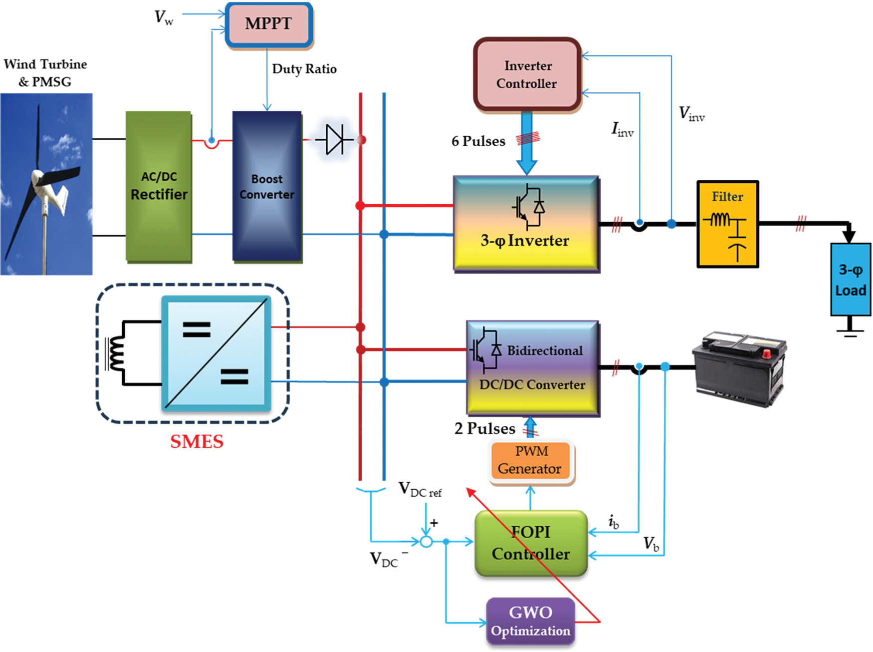
Figure 1: The structure of the proposed system
Linearized and simple transfer functions are usually used to model microgrids [27]. However, transfer function modelling has many limitations, such as approximations of real-world systems. These simplifications may not capture all the intricacies of the actual system behavior, leading to inaccuracies in the analysis and design. In contrast, the differential equation model offers a complete and explicit representation of the system’s dynamics in terms of its physical parameters and the laws governing its behavior. Hence, the detailed dynamic model for each microgrid component will be explained in the following.
The wind turbine’s dynamic model can be obtained by [1]:
All symbols are defined and listed in the nomenclature by the top of the manuscript.
Both permanent magnet synchronous motors and PMSGs have the same mathematical model (PMSM). The voltage and current relations below represent PMSG:
where (Vd, Vq) are the d-q axes voltages, (ra) is the stator resistance, (id, iq) are the d-q axes currents, and (Ld, Lq) are the d-q inductances. The electrical speed of rotation is (ωe), and (λm) is the permanent magnetic flux.
The proposed microgrid includes four power electronic converters, namely:
• AC/DC converter
• SMES converter
• Battery storage converter
• DC/AC converter
The detailed model of those converters is explained in the following paragraphs.
The purpose of this converter is to regulate the PMSG output power. As the wind turbine power varies perpetually, the output voltage and frequency of the PMSG have random variations. One of the common ways to regulate the output power of the PMSG is to rectify its output voltage and smooth it with the help of a capacitor filter. The traditional 3-ϕ diode rectifier is implemented for this microgrid. It has been modelled as a gain [1].
Superconducting materials are the focal point of the SMES system because they exhibit zero dissipation since they are impervious to outside forces. These components go inside the coil in order to reduce conductive energy loss.
The magnetic field stores high-density energy. Maintaining the coil in the superconducting state, where the cryogenic system can function effectively and where a protective mechanism is there to safeguard the SMES under erratic conditions, is the main issue faced by the SMES unit systems. Electronic converter circuits can be used to regulate the impedances between the microgrid and the SMES coil. Fig. 2a shows the DC/DC bidirectional converter utilized in the microgrid to achieve SMES’s control. The stored power and energy of the SMES’s coil are given by:
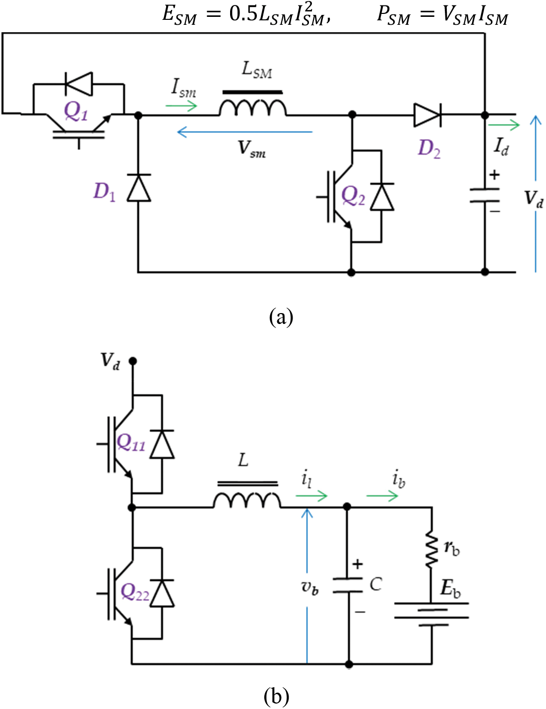
Figure 2: (a) The SMES’s bidirectional converter and (b) The battery storage converter
Fig. 2a illustrates how the average power exchange by the SMES system may be adjusted in a flexible state during each switching period by varying the switches’ duty cycle (d) of the switches (Q1 and Q2). The relationship between the SMES’s power and current is represented by [28]:
The SMES will charge when (d) is greater than 0.5 since it will absorb energy by carrying the source current from (Q1 and Q2). In other places, if (d) is less than 0.5, the SMES will conduct the diodes (D1 and D2) to release the stored energy into the DC-bus.
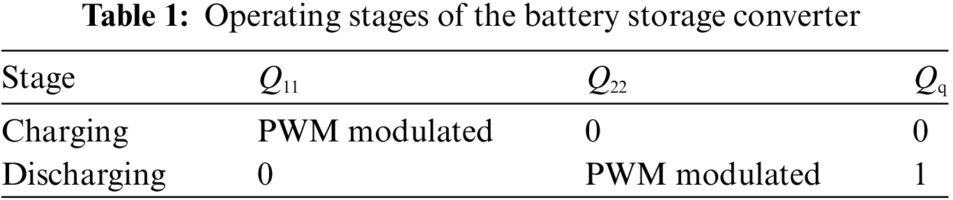
3.3.3 Battery Storage Converter
Fig. 2b demonstrates the structure of the battery storage converter’s circuit. It is a half-bridge DC/DC converter that can provide power in both ways. The main job of this converter is to regulate the battery charging. The converter’s terminals are connected to the battery and the DC bus. This converter may function in two stages: the charging and discharging stage. The operation stage is decided by the controller and depends on the switching state of the switches (Q11 and Q22), according to Table 1.
The converter voltage and currents can be modeled in both stages using:
where (Q11 and Q22) are the switching logic of the converter switches, (Qq) is a switching logic function, (rb, Eb) are the internal resistance and the voltage of the battery, (vb, il) are the capacitor voltage and inductor current, (C, L) is capacitance and inductance of the filter.
This converter’s purpose is to provide the AC load with the suitable rms voltage value and frequency. It must regulate these quantities against all load and DC bus disturbances. The converter has the traditional 6-switches inverter circuit with a smoothing filter, as shown in Fig. 3. Its input is the switching logic function of the switches (
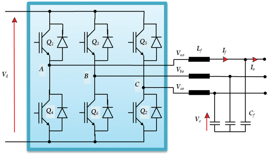
Figure 3: The DC/AC converter
The DC-link regulator utilizes the duty ratio of the converter in the energy storage to control the DC-link effectively, as shown in Fig. 4. The battery energy storage converter’s controller manages the DC bus voltage and oversees the energy storage system’s charge and discharge functions. Moreover, the SMES controller will support it when the hybrid scheme is applied. This controller is composed of two distinct loops: the initial loop, known as the outer loop, is responsible for governing the DC bus voltage, whereas the subsequent loop, referred to as the inner loop, is in charge of maintaining the SMES current at a desired level by the outer loop. Ensuring a stable DC-link voltage is of utmost importance when it comes to the charging process of electric vehicles, which are anticipated to be highly promising shortly. This is crucial because the smooth functioning of the vehicle heavily relies on the maintenance of this voltage across the charger’s terminals.
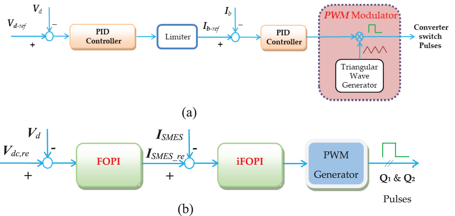
Figure 4: Structure of each control stage of the microgrid based on RESs: (a) BESS controller and (b) SMES proposed controller
The main goal of the DC-link regulator is to ensure that the DC-link voltage (Vdc) remains constant at a specific desired value (Vdc-ref). In order to accomplish this, the controller modifies the discharging and charging operations of the SMES. The fast response capability of the SMES will be utilized to effectively address the disturbances caused by variations in load and fluctuations in wind power within the system. The suggested controller is built using both dual loops’ fractional-order proportional integral (FOPI) technique. This FOPI method is utilized to create the inner loop of the proposed controller, which ensures the stability of the DC-link. On the other hand, the outer loop is designed using an intelligent FOPI approach incorporating the ULM (ultra-local model) to regulate the SMES current effectively.
4.1 Proposed Fractional-Order Controller
Using fractional parameters in the controller allows for the expression of any number using a complex and differential notation or adaptable integral [29,30]. This utilization provides a wide range of possibilities and flexibility in representing numerical values precisely and comprehensively. The correlation between the fractional order (FO) differential and the integral operator can be mathematically described by a function that considers the specific order q involved:
where lb refers to the lower band and ub indicates the upper band.
When the order q of the order is greater than zero (i.e., q > 0), it falls under the category of a FO differential transfer function. Conversely, if the order q is less than zero (i.e., q < 0), it is categorized as a first-order integral.
Numerous explanations are provided in the literature to facilitate a better understanding of fractional order, which can often be difficult to grasp in terms of its physical implications. The Riemann-Liouville approach, which is a type of definition, provides a technique for computing the order derivative of a function. By employing this approach, we can gain a deeper comprehension of the fundamental principles behind fractional order (FO) [31]:
where n ∈ N, n − 1 < q < n, and the Gamma function
The fractional derivative in Eq. (13) can be converted into the solution of Eq. (14) using the Laplace method [29]. Caputo’s definition provides a second interpretation of the theory of fractional order (FO), specifically in relation to the representation of the q order of the function f(t) in the time domain, as shown in Eq. (15). This definition expands our understanding of FO and allows us to analyze functions with fractional orders more comprehensively [32].
When the Laplace transformation is performed on Eq. (15), the Equation’s integral order is accompanied by specific starting conditions. These conditions are important physically and can be elucidated using Eq. (6), wherein the Laplace operator is denoted as s.
Utilizing FO operators in the time domain necessitates engaging in intricate mathematical computations. The recursive approximation technique is commonly employed to implement FO operators [33,34]. The Laplace transformation provides a means to express the qth derivative in an alternative mathematical form, see Eq. (16). This method allows for a different representation of the derivative.
where
and N is the approximation order of the Oustaloup method in the effective frequency range [
The current research employs a FO proportional integral controller with three tuning parameters: proportional gain (Kp), integral gain (Ki), and integral fractional order λ. Controllers configured using these specific parameters have been found to demonstrate improved stability, transient response, and overall accuracy compared to traditional PI regulators. In addition, this controller offers enhanced adaptability and robustness in the face of system disturbances, enabling it to proficiently manage a wide range of disruptions. Simultaneously, Fig. 5 depicts the fundamental layout of the control structure. The Ziegler-Nichols approach is used to adjust the traditional PI controller’s proportion and integral gains.
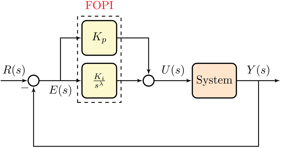
Figure 5: The foundational structure of the FOPI controller
This sums up the experimental Ziegler-Nichols tuning procedure in a straightforward manner. Initially, the proportional section of the PI controller—which has a very low proportional gain—is all that remains and the integral part is set to zero. After that, the proportional gain is raised until the output signal begins to oscillate continuously. Keep in mind that the controller should not be reaching its limitations when the oscillations happen. You might need to adjust the setpoint after every gain increase to see if the loop oscillates. With an oscillation period (Tosc), the oscillations happen at a critical proportional gain (Kpc). The proportional and integral gains (Kp, Ki) for the PI controller are modified as follows by monitoring the parameters (Kpc, Tosc).
In addition, Eq. (18) demonstrates the complete representation of the transfer function of the FOPI in Laplace form, which is referred to as Gc(s), where λ is frequently in the range of [0,1].
The DC-link voltage is continuously observed and compared to a predetermined reference voltage, Vdc,ref. The responsibility of the FOPI controller is to control the voltage differential by generating the required SMES reference value (ISMES_ref) as given in Eq. (20). This reference value aids in ensuring the appropriate control and management of Vdc. Hence, the desired SMES current, as calculated by the reference, is compared to the measured battery current. The FOPI controller uses this comparison to calculate and adjust the duty ratio of the converter. The nested control loops’ system guarantees that the current drawn from the SMES stays within a safe range, thus offering protection.
where Kpv, Kiv, and λv are the proportional gain, integral gain, and the fractional order of the outer voltage loop control.
4.2 Intelligent FOPI Based on Ultra-Local Model Control
The alterations in the single-input single-output (SISO) system can be estimated using a finite-dimensional differential equation [35]:
where E denotes a non-linear function, u indicates the system’s input, y indicates the system’s output, and (n, m) specify the control orders of the system’s output and input, respectively. The ULM, depicted in Fig. 6, is characterized by its fundamental structure. In this structure, F represents the cumulative uncertainties and disturbances within the ULM system. By measuring the output of the system and utilizing prior control input, the unknown function F can be determined. Furthermore, it is also feasible to streamline the process of simplifying Eq. (21) by employing the ULM principle as follows:
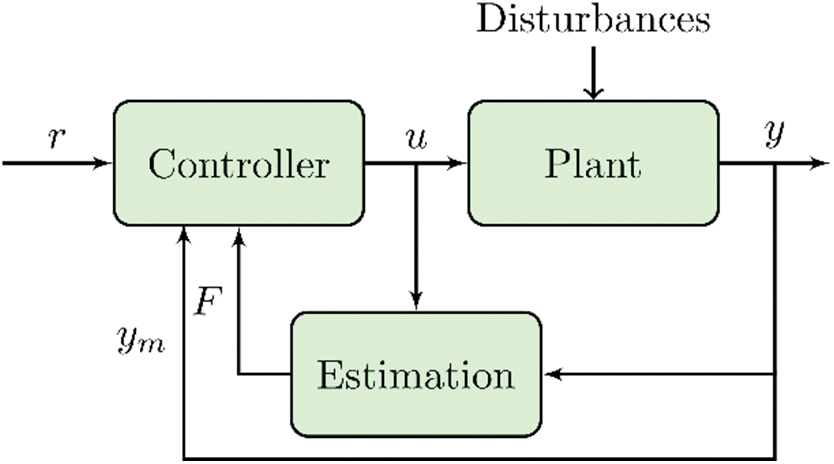
Figure 6: The basic structure of the ultra-local model
where
Due to the fact that the value of F is merely an approximation and is not precise, it is possible to replace it with the symbol
where L has a small value based on the noise intensity and the sampling period Ts. Finally, the Heun method offers a viable solution for determining the value of
where
In the present study, it can be observed from Fig. 7 that the ULM component is integrated into the FOPI controller to effectively regulate the current of the SMES in the inner loop. As a result, the controller’s general architecture can be referred to as an intelligent integral (i.e., iFOPI) as it eliminates the necessity of employing a model in the controller.
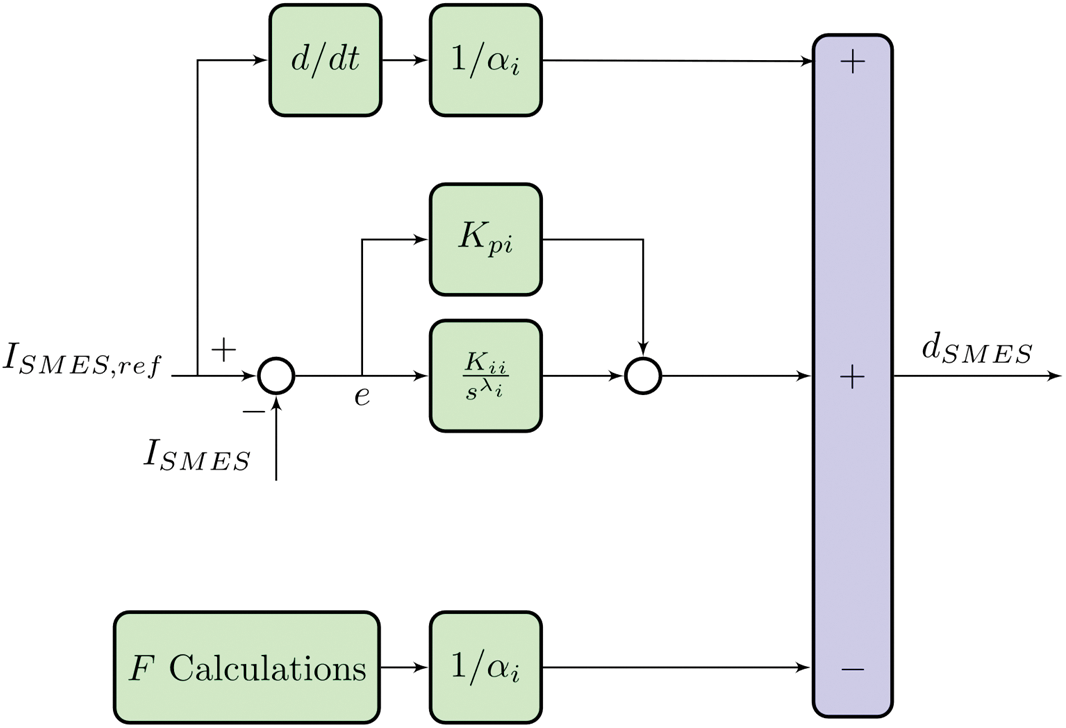
Figure 7: Structure of the proposed iFOPI for the inner loop of the SMES controller
By adopting this control strategy, the issues related to parameter mismatches, which often lead to malfunctions in the power system, can be successfully addressed. The control input of the proposed controller, known as the duty-cycle (dSMES) of the SMES DC-DC chopper, is mathematically expressed in Eq. (25), wherein the Laplace operator is denoted by the variables.
4.3 Objective Function Definition
The process of determining the FOPI+iFOPI parameters through trial and error is a complex task that heavily relies on the expertise and knowledge of the practitioner. Finding suitable values for these parameters can be a daunting challenge. Nevertheless, in order to enhance the system’s functionality preserve its stability, and prevent interruptions, time and effort must be put into this procedure. In order to do this, the most optimum values for the parameters of the FOPI+iFOPI controller are identified efficiently by applying the dandelion optimizer (DO) metaheuristic optimization approach. The DO stands out as a novel metaheuristic optimization algorithm, drawing inspiration from the movement patterns of dandelion seeds. The DO boasts several advantages over alternative algorithms. These include its simplicity, making it easy to implement; minimal storage and computational requirements; swift convergence facilitated by the continuous reduction of the search space and a smaller number of decision variables; and adeptness at avoiding local minima. Table 2 provides a summary of the parameters associated with the DO. The fitness function used for the DO in Eq. (26) is the integral square error (ISE), in which
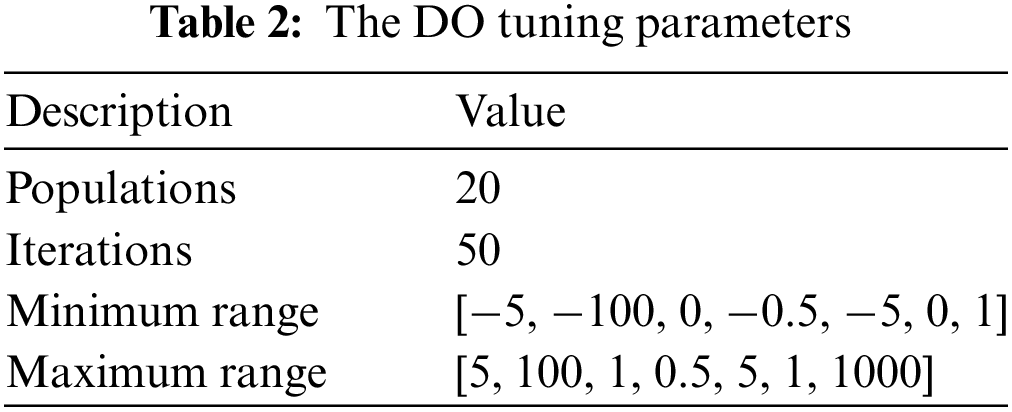
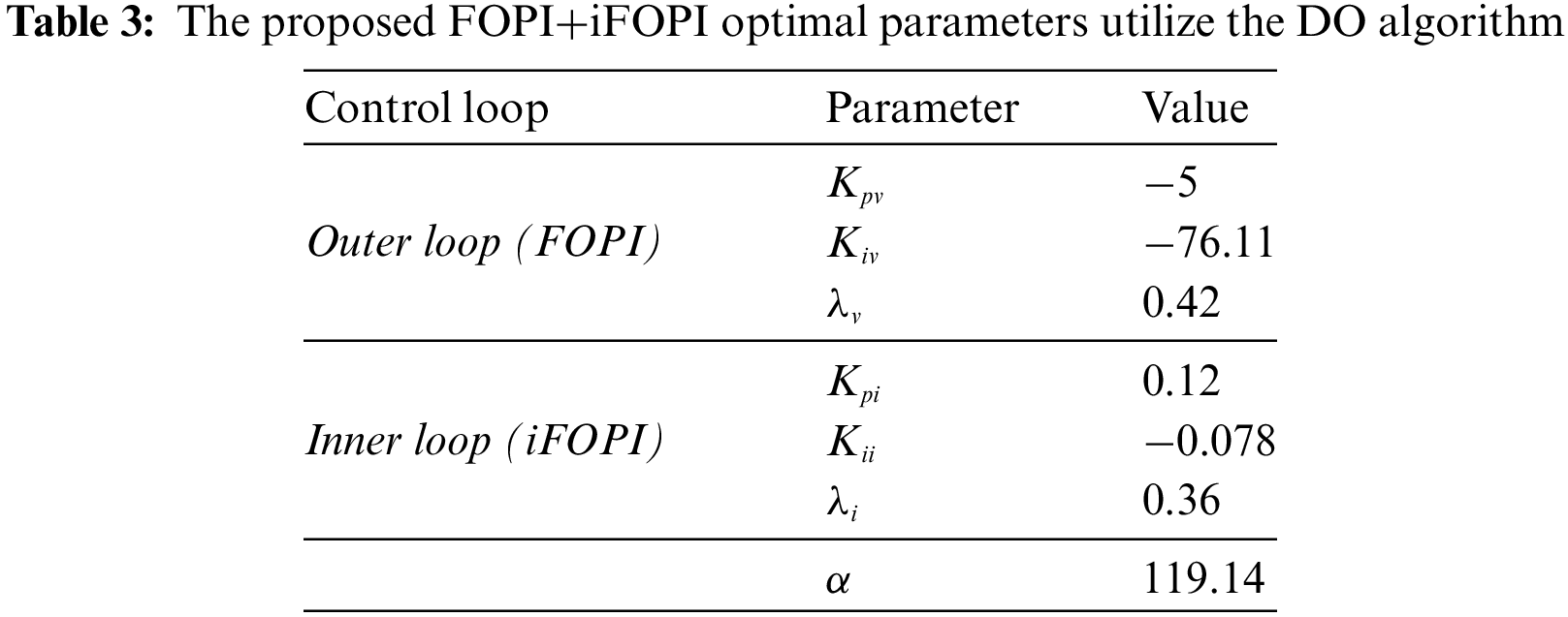

Figure 8: Convergence curve of the DO algorithm
5 Simulation Results and Discussion
The suggested microgrid with the optimum controller, illustrated in Fig. 1, was validated using digital computer simulations. The MATLAB software package was used to model and test this system in order to accommodate several operating strategies for variations in wind speed and load parameters. The Simulink model is depicted in Fig. 9, and the sampling time is 20 µs.
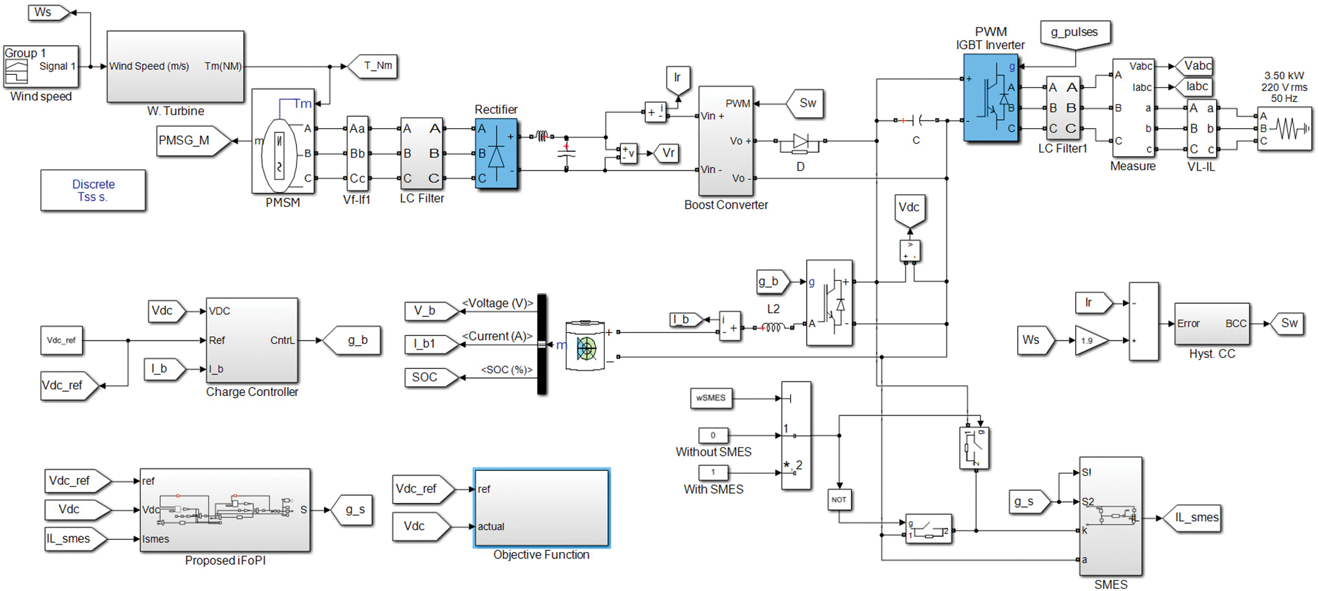
Figure 9: The simulink model of the studied system
The microgrid specifications are selected as the wind turbine (h = 4 m, A = 4 m2, ρ = 1.25 kg/m2, and R = 1 m); DC-link voltage (300 V); filter (Cf = 2 µF, Lf = 3 mH); and load (110 V and 50 Hz). The responsiveness of the microgrid was tested with varied loads and wind speed in steps. The results are classified into two cases. Case #1 explains the effectiveness of using SMES with the proposed controller. While case #2 investigates the effectiveness of the proposed controller.
5.1 Effectiveness of Using SMES with the Proposed Controller
The simulation results with/without SMES are shown in Figs. 10 and 11. As illustrated in Fig. 10a, the microgrid was exposed to step fluctuations in wind speed. The wind velocity was kept at 12 m/s for the first 0.3 s period, decreased to 6.5 m/s during the second 0.3 s period (at time of 0.6 s), increased to 14 m/s at the time 0.6 s until 1 s dropped to 0.8 m/s at the time of 1 s until 1.35 s, and vanishes for the rest of the time axis. The performance of the DC bus voltage with/without SMES is presented in Fig. 10b. It is opposed that the presence of the SMES greatly improved the DC bus voltage performance. The settling times and overshoots are improved and shortened by >100%. Fig. 10c illustrates the ISE objective function for the system, both with and without SMES. It is evident that employing the SMES system results in a 72% reduction in the objective function compared to not utilizing the SMES. The SMES coil current response with SMES is shown in Fig. 10d. It is noticed that the SMES energy and current are continuously decreasing when the wind energy is zero at the period [1.35 s, 2 s] in Fig. 10d. Also, the fast changes in the SMES energy and current are related to the wind energy transients. With SMES, the coil charges and discharges according to the controller commands, maintaining the DC bus voltage at its specified reference level. Also, the SMES current increases rapidly when the wind increases and vice versa. This issue helps in damping the system oscillations and unwanted transients. Hence, the presence of SMES in the system improves the transient performance.
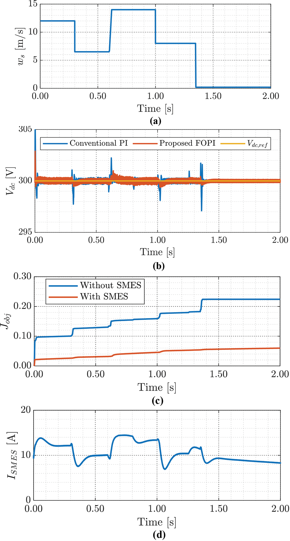
Figure 10: The simulation results of the intended system (a) wind speed, (b) DC bus voltage with/without SMES, (c) objective function with/without SMES, and (d) SMES coil current
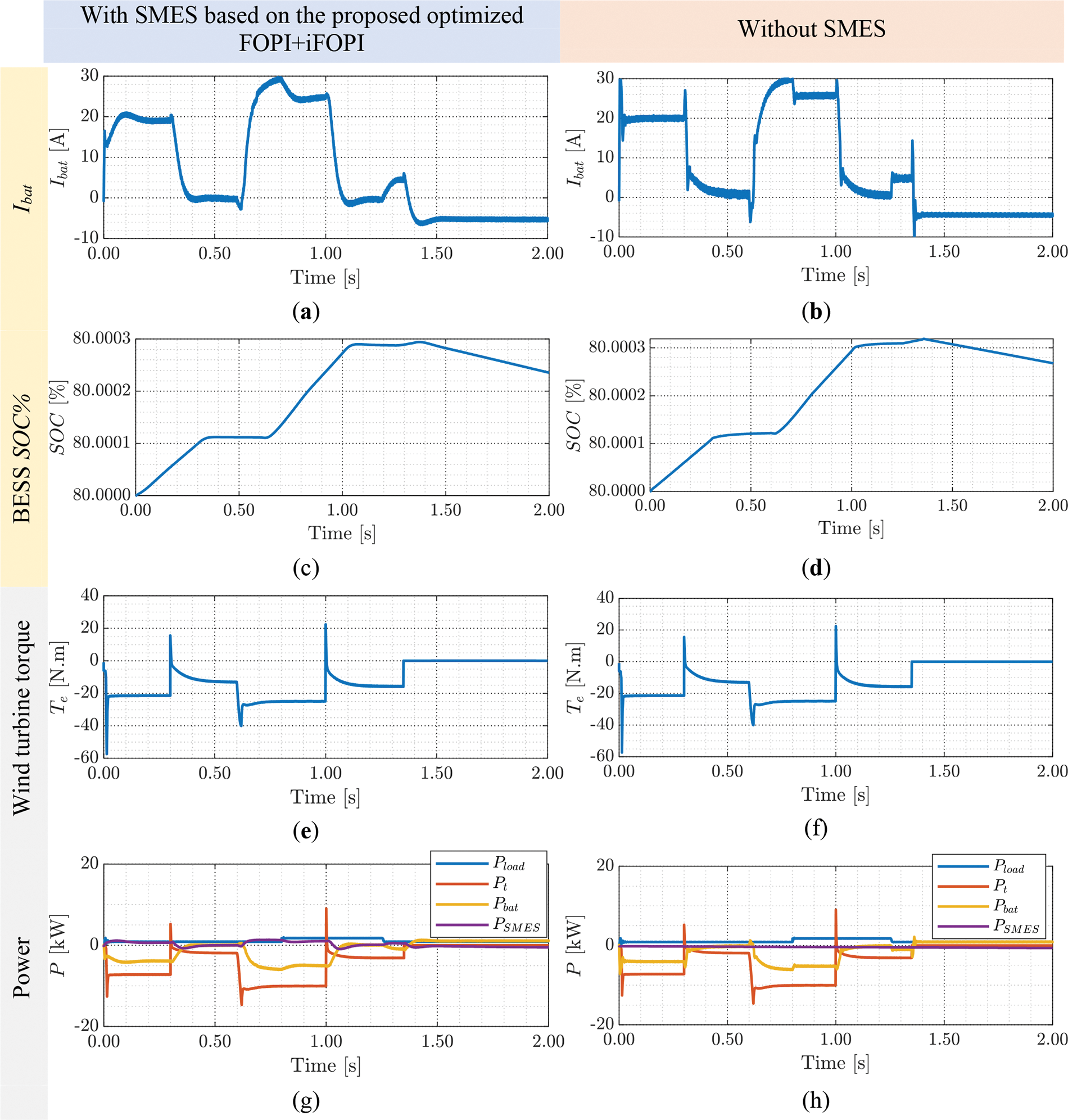
Figure 11: Comparison of the simulation results of the intended system based on optimized FOPI+iFOPI with/without SMES (a, b) battery current, (c, d) battery SOC, and (e, f) wind turbine torque (g, h) power
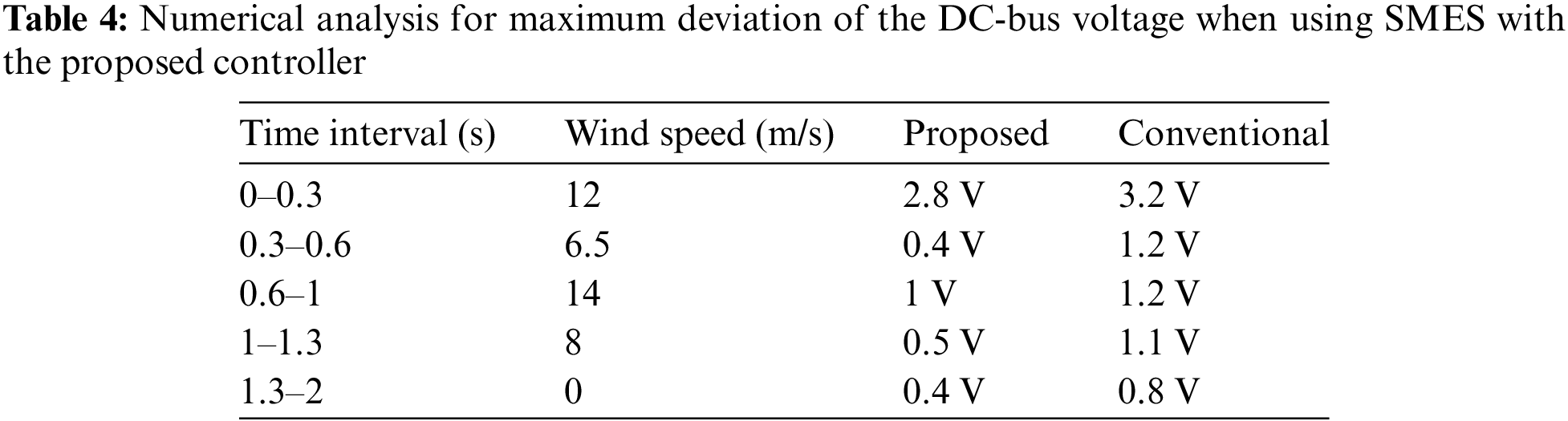
Fig. 11 compares the simulation results of the intended system based on optimized FOPI+iFOPI with/without SMES. The battery current responses, with/without SMES, are illustrated in Figs. 11a and 11b. At first sight, the battery current response with SMES has damped transients compared to that without SMES. Moreover, the battery current charges and discharges the battery according to the state of the wind energy in both cases. Figs. 11c and 11d present the battery’s state of charge (SOC) with/without SMES. It is noticed that the battery is charging during the periods where the wind energy is available, at the period [0 s, 1.35 s]. Nevertheless, the battery is discharging during the period when the wind energy is unavailable, at the period [1.35 s, 2 s]. The response of SOC is identical for both cases. The wind turbine torque responses for the two cases are displayed in Figs. 11e and 11f. The turbine torque varies with wind speed in such a way as to produce the turbine’s maximum output power. Actually, the torque is related to the PMSG current that is decided by the boost converter controller. Figs. 11g and 11h present nearly all significant powers in the microgrid for the two states with/without SMES. It is seen that the SMES power is zero in the case without the SMES coil. However, the SMES power is integrated with the battery power to improve the response and manage the energy status of the microgrid. The total powers are identical for the two cases. Table 4 presents the numerical analysis for the maximum deviation of the DC-bus voltage when using SMES with the proposed controller compared to the conventional controller. The DC-bus voltage is usually smaller with the proposed controller than the conventional controller.
5.2 Effectiveness of the Proposed Controller
The simulation results with SMES using the conventional PI controller and the proposed FOPI+iFOPI controller are shown in Figs. 12 and 13. As illustrated in Fig. 12a, the system was exposed to step fluctuations in wind speed, the same as before. The performance of the DC bus voltage with SMES using the conventional PI controller and the proposed FOPI+iFOPI controller is presented in Fig. 12b. It is obvious that the proposed FOPI+iFOPI controller has an improvement in the DC bus voltage performance. The settling times and overshoots are improved and shortened by >5%. Fig. 12c illustrates the ISE objective function for the system, both with SMES. It is evident that employing the SMES system based on the proposed optimal FOPI+iFOPI results in a 33.3% reduction in the objective function compared to utilizing the SMES based on the conventional PI.
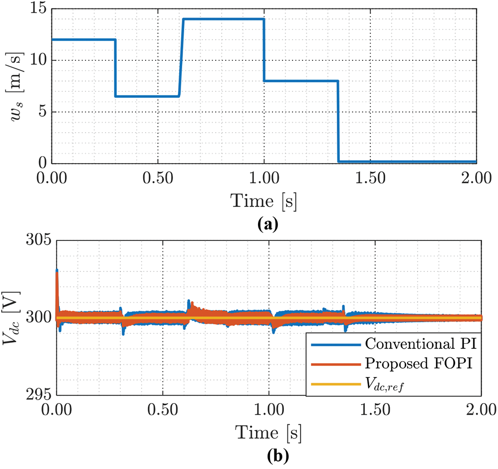
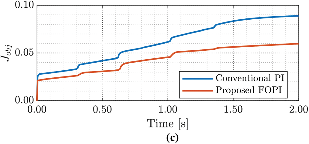
Figure 12: The simulation results of the intended system with SMES (a) wind speed, (b) DC bus voltage using PI/(FOPI+iFOPI), (c) and objective function using PI/(FOPI+iFOPI)
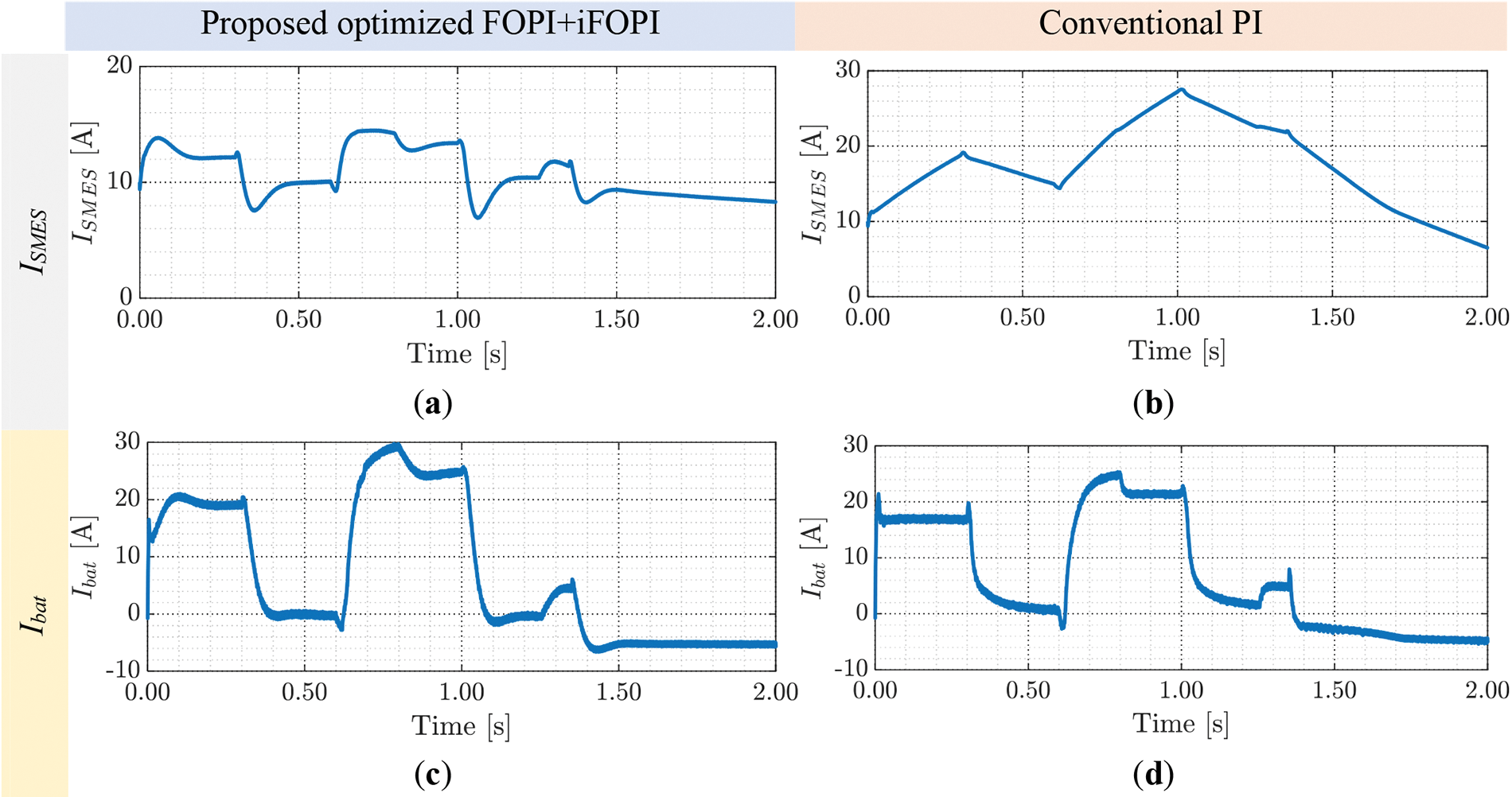
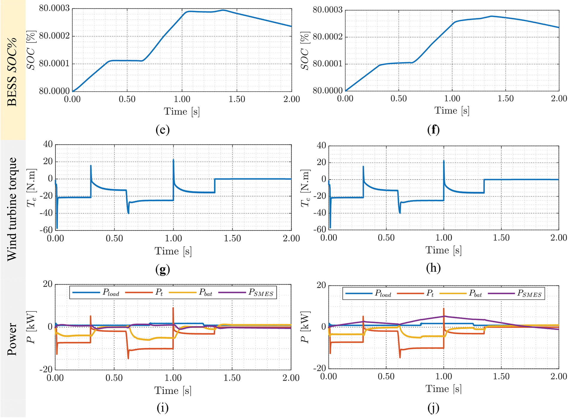
Figure 13: Comparison of the simulation results of the intended system with SMES based on optimized (FOPI+iFOPI)/PI (a, b) the SMES coil’s current, (c, d) battery current, (e, f)battery SOC, (g, h) wind turbine torque, and (i, j) microgrid salient powers
Fig. 13 compares the simulation results of the intended system with SMES based on the optimized FOPI+iFOPI and the conventional PI controllers. Figs. 13a and 13b present the SMES coil’s current responses with SMES using both controllers. Figs. 13c and 13d illustrate the battery current responses using both controllers. Compared to the battery current response without SMES, the response with SMES seems more damped. Furthermore, in both scenarios, the battery current charges and discharges the battery based on the wind energy level. Figs. 13e and 13f show the battery’s SOC using both controllers. In both situations, the SOC’s response is the same. Figs. 13g and 13h show the wind turbine torque responses for the two scenarios. Virtually all important powers in the microgrid using the two controllers are shown in Figs. 13i and 13j. In both circumstances, the overall capabilities are nearly the same.
This paper introduces a hybrid dual-loop control method to stabilize the DC-link in a DC microgrid. The utilization of a superconducting magnetic energy storage (SMES) device is proposed to complement the battery energy storage system, effectively mitigating the impact of fluctuations in wind speed, which leads to intermittent power generation from wind turbines. The proposed control for the SMES is structured with two loops: an outer loop utilizing the fractional-order PI (FOPI) controller to regulate the DC-link voltage and an inner loop employing the intelligent FOPI (iFOPI) to regulate the SMES current. The parameters of FOPI and iFOPI are optimized using the dandelion optimizer (DO) approach to achieve optimal performance.
Simulation results demonstrate the superior performance of the proposed controller, even under varying wind speed profiles, when compared to scenarios without the SMES unit or using a conventional PI controller for the SMES system. Moreover, implementing the proposed optimal FOPI+iFOPI results in a 33.3% reduction in the objective function compared to the conventional PI-based SMES system. This reduction holds significant implications for developing hybrid distributed energy systems, fostering the widespread integration of renewable energy sources (RESs) globally. Future work could focus on developing an energy management system between the BESS and SMES to optimize their power outputs in alignment with the proposed controller.
Acknowledgement: The authors extend their appreciation to the Deputyship for Research and Innovation, Ministry of Education, Saudi Arabia for funding this research work.
Funding Statement: This research was funded by the Deputyship for Research and Innovation, Ministry of Education, Saudi Arabia, through the University of Tabuk, Grant Number S-1443-0123.
Author Contributions: S.Z. and H.A. handled the formal analysis, modeling and conception, S.Z. and A.M. investigated the methodology; A.B. tuned the controllers; A.B., A.M., and H.A. wrote original draft, reviewed and edited; A.M.K and I.E. assisted with funding acquisition. After reading the published version of the article, all writers have given their approval.
Availability of Data and Materials: All the data and materials are available within the manuscript.
Conflicts of Interest: The authors declare that they have no conflicts of interest to report regarding the present study.
References
1. Zaid, S. A., Kassem, A. M., Alatwi, A. M., Albalawi, H., AbdelMeguid, H. et al. (2023). Optimal control of an autonomous microgrid integrated with super magnetic energy storage using an artificial bee colony algorithm. Sustainability, 15(11), 8827. https://doi.org/10.3390/su15118827 [Google Scholar] [CrossRef]
2. Albalawi, H., El-Shimy, M. E., AbdelMeguid, H., Kassem, A. M., Zaid, S. A. (2022). Analysis of a hybrid wind/photovoltaic energy system controlled by brain emotional learning-based intelligent controller. Sustainability, 14(8), 4775. https://doi.org/10.3390/su14084775 [Google Scholar] [CrossRef]
3. Mosadeghy, M., Yan, R., Saha, T. K. (2015). A time-dependent approach to evaluate capacity value of wind and solar PV generation. IEEE Transactions on Sustainable Energy, 7(1), 129–138. [Google Scholar]
4. Gnana, K. Lazard’s levelized cost of energy analysis—version 10. https://www.lazard.com/media/438038/levelized-cost-of-energy-v100.pdf (accessed on 23/12/2016). [Google Scholar]
5. Barnard, M. 7 factors show wind solar 1st choices. (2016). https://cleantechnica.com/2016/07/11/7-factors-show-wind-solar-1st-choices/ (accessed on 11/07/2016). [Google Scholar]
6. Nehrir, M. H., Wang, C., Strunz, K., Aki, H., Ramakumar, R. et al. (2011). A review of hybrid renewable/alternative energy systems for electric power generation: Configurations, control, and applications. IEEE Transactions on Sustainable Energy, 2(4), 392–403. [Google Scholar]
7. Chauhan, A., Saini, R. P. (2014). A review on integrated renewable energy system based power generation for stand-alone applications: Configurations, storage options, sizing methodologies and control. Renewable and Sustainable Energy Reviews, 38, 99–120. https://doi.org/10.1016/j.rser.2014.05.079 [Google Scholar] [CrossRef]
8. Koohi-Kamali, S., Abd Rahim, N. (2016). Coordinated control of smart microgrid during and after islanding operation to prevent under frequency load shedding using energy storage system. Energy Conversion and Management, 127, 623–646. https://doi.org/10.1016/j.enconman.2016.09.052 [Google Scholar] [CrossRef]
9. Saeed, M. H., Wang, F. Z., Kalwar, B. A., Iqbal, S. (2021). A review on microgrids’ challenges & perspectives. IEEE Access, 9, 166502–166517. https://doi.org/10.1109/access.2021.3135083 [Google Scholar] [CrossRef]
10. Liu, X., Wang, P., Loh, P. C. (2011). A hybrid AC/DC microgrid and its coordination control. IEEE Transactions on Smart Grid, 2(2), 278–286. https://doi.org/10.1109/TSG.2011.2116162 [Google Scholar] [CrossRef]
11. Singh, B., Kasal, G. K. (2008). Voltage and frequency controller for a three-phase four-wire autonomous wind energy conversion system. IEEE Transactions on Energy Conversion, 23(2), 509–518. https://doi.org/10.1109/TEC.2008.918620 [Google Scholar] [CrossRef]
12. Sumarmad, K. A. A., Sulaiman, N., Wahab, NIA., Hizam, H. (2022). Microgrid energy management system based on fuzzy logic and monitoring platform for data analysis. Energies, 15, 4125. https://doi.org/10.3390/en15114125 [Google Scholar] [CrossRef]
13. Wang, Z., Jia, Y., Cai, C., Chen, Y., Li, N. et al. (2021). Study on the optimal configuration of a wind-solar-battery-fuel cell system based on a regional power supply. IEEE Access, 9, 47056–47068. https://doi.org/10.1109/ACCESS.2021.3064888 [Google Scholar] [CrossRef]
14. Mammadov, F. F. (2019). Fuzzy logic controller application in HybriD solar and wind energy system. 2019 International Artificial Intelligence and Data Processing Symposium (IDAP), pp. 1–4. Malatya, Turkey. https://doi.org/10.1109/IDAP.2019.8875960 [Google Scholar] [CrossRef]
15. Lee, D. J., Wang, L. (2008). Small-signal stability analysis of an autonomous hybrid renewable energy power generation/energy storage system part I: Time-domain simulations. IEEE Transactions on Energy Conversion, 23(1), 311–320. https://doi.org/10.1109/TEC.2007.914309 [Google Scholar] [CrossRef]
16. Manusov, V., Nazarov, M. (2020). Energy consumption conditions optimization of the autonomous system based on carbon-free energy. 2020 Ural Smart Energy Conference (USEC), pp. 93–96. Ekaterinburg, Russia, IEEE. https://doi.org/10.1109/USEC50097.2020.9281208 [Google Scholar] [CrossRef]
17. Koohi-Fayegh, S., Rosen, M. A. (2020). A review of energy storage types, applications and recent developments. Journal of Energy Storage, 27, 101047. [Google Scholar]
18. Luo, X., Wang, J., Dooner, M., Clarke, J. (2015). Overview of current development in electrical energy storage technologies and the application potential in power system operation. Applied Energy, 137, 511–536. https://doi.org/10.1016/j.apenergy.2014.09.081 [Google Scholar] [CrossRef]
19. Alafnan, H., Pei, X., Khedr, M., Alsaleh, I., Albaker, A. et al. (2023). The possibility of using superconducting magnetic energy storage/battery hybrid energy storage systems instead of generators as backup power sources for electric aircraft. Sustainability, 15(3), 1806. https://doi.org/10.3390/su15031806 [Google Scholar] [CrossRef]
20. Muresan, C. I., Birs, I., Ionescu, C., Dulf, E. H., de Keyser, R. (2022). A review of recent developments in autotuning methods for fractional-order controllers. Fractal and Fractional, 6(1), 37. https://doi.org/10.3390/fractalfract6010037 [Google Scholar] [CrossRef]
21. Raver, J. E., Nuevo-Gallardo, C., Tejado, I., Fernández-Portales, J., Ortega-Morán, J. F. et al. (2022). Cardiovascular circulatory system and left carotid model: A fractional approach to disease modeling. Fractal and Fractional, 6(2), 64. https://doi.org/10.3390/fractalfract6020064 [Google Scholar] [CrossRef]
22. Saleem, O., Ali, S., Iqbal, J. (2023). Robust MPPT control of stand-alone photovoltaic systems via adaptive self-adjusting fractional order PID controller. Energies, 16(13), 5039. https://doi.org/10.3390/en16135039 [Google Scholar] [CrossRef]
23. Çelik, E. (2021). Design of new fractional order PI-fractional order PD cascade controller through dragonfly search algorithm for advanced load frequency control of power systems. Soft Computing, 25(2), 1193–1217. https://doi.org/10.1007/s00500-020-05215-w [Google Scholar] [CrossRef]
24. Arya, Y., Kumar, N., Dahiya, P., Sharma, G., Çelik, E. et al. (2021). Cascade-IλDμN controller design for AGC of thermal and hydro-thermal power systems integrated with renewable energy sources. IET Renewable Power Generation, 15(3), 504–520. https://doi.org/10.1049/rpg2.v15.3 [Google Scholar] [CrossRef]
25. Arya, Y., Dahiya, P., Çelik, E., Sharma, G., Gözde, H. et al. (2021). AGC performance amelioration in multi-area interconnected thermal and thermal-hydro-gas power systems using a novel controller. Engineering Science and Technology, an International Journal, 24(2), 384–396. https://doi.org/10.1016/j.jestch.2020.08.015 [Google Scholar] [CrossRef]
26. Çelik, E., Öztürk, N. (2022). Novel fuzzy 1PD-TI controller for AGC of interconnected electric power systems with renewable power generation and energy storage devices. Engineering Science and Technology, an International Journal, 35, 101166. https://doi.org/10.1016/j.jestch.2022.101166 [Google Scholar] [CrossRef]
27. Pan, I., Das, S. (2014). Kriging based surrogate modeling for fractional order control of microgrids. IEEE Transactions on Smart Grid, 6(1), 36–44. [Google Scholar]
28. Ghardash, K. N. (2022). Improving dynamic response of PEMFC using SMES and bidirectional DC/DC converter. Automatika, 63(4), 745–755. https://doi.org/10.1080/00051144.2022.2066768 [Google Scholar] [CrossRef]
29. Zaid, S. A., Bakeer, A., Magdy, G., Albalawi, H., Kassem, A. M. et al. (2023). A new intelligent fractional-order load frequency control for interconnected modern power systems with virtual inertia control. Fractal and Fractional, 7(1), 62. https://doi.org/10.3390/fractalfract7010062 [Google Scholar] [CrossRef]
30. Albalawi, H., Bakeer, A., Zaid, S. A., Aggoune, E. H., Ayaz, M. et al. (2023). Fractional-order model-free predictive control for voltage source inverters. Fractal and Fractional, 7(6), 433. https://doi.org/10.3390/fractalfract7060433 [Google Scholar] [CrossRef]
31. Bingi, K., Rajanarayan Prusty, B., Pal Singh, A. (2023). A review on fractional-order modelling and control of robotic manipulators. Fractal and Fractional, 7(1), 77. https://doi.org/10.3390/fractalfract7010077 [Google Scholar] [CrossRef]
32. Almasoudi, F. M., Magdy, G., Bakeer, A., Alatawi, K. S. S., Rihan, M. (2023). A new load frequency control technique for hybrid maritime microgrids: Sophisticated structure of fractional-order PIDA controller. Fractal and Fractional, 7(6), 435. https://doi.org/10.3390/fractalfract7060435 [Google Scholar] [CrossRef]
33. Oustaloup, A., Levron, F., Mathieu, B., Nanot, F. M. (2000). Frequency-band complex noninteger differentiator: Characterization and synthesis. IEEE Transactions on Circuits and Systems I: Fundamental Theory and Applications, 47(1), 25–39. https://doi.org/10.1109/81.817385 [Google Scholar] [CrossRef]
34. Morsali, J., Zare, K., Hagh, M. T. (2017). Applying fractional order PID to design TCSC-based damping controller in coordination with automatic generation control of interconnected multi-source power system. Engineering Science and Technology, an International Journal, 20(1), 1–17. https://doi.org/10.1016/j.jestch.2016.06.002 [Google Scholar] [CrossRef]
35. Fliess, M. (2009). Model-free control and intelligent PID controllers: Towards a possible trivialization of nonlinear control? IFAC Proceedings Volumes, 42(10), 1531–1550.https://doi.org/10.3182/20090706-3-FR-2004.00256 [Google Scholar] [CrossRef]
36. Zaid, S. A., Bakeer, A., Albalawi, H., Alatwi, A. M., Abdeldaim, H. et al. (2023). Model-free predictive current control of a 3-φ grid-connected neutral-point-clamped transformerless inverter. Energies, 16(7), 3141. https://doi.org/10.3390/en16073141 [Google Scholar] [CrossRef]
37. Bento, F., Jlassi, I., Cardoso, A. J. M. (2021). Model-free predictive control of interleaved DC-DC converters, based on ultra-local model, with constant switching frequency. Proceeding of 2021 IEEE Energy Conversion Congress and Exposition (ECCE), pp. 2022–2028. Vancouver, BC, Canada, IEEE. https://doi.org/10.1109/ECCE47101.2021.9595318 [Google Scholar] [CrossRef]
Cite This Article
 Copyright © 2024 The Author(s). Published by Tech Science Press.
This work is licensed under a Creative Commons Attribution 4.0 International License , which permits unrestricted use, distribution, and reproduction in any medium, provided the original work is properly cited.
 Downloads
 Citation Tools