
 Submit a Paper
 Propose a Special lssue
 Open Access
ARTICLE

Experimental and Finite Element Analysis of Corroded High-Pressure Pipeline Repaired by Laminated Composite
1 Faculty of Mechanical Engineering, Tarbiat Modares University, Tehran, 1411713116, Iran
2 A. Leon Linton Department of Mechanical, Robotics and Industrial Engineering, Lawrence Technological University, Southfield, MI, 48075, USA
3 Department of Mechanical Engineering, Faculty of Engineering, Meybod University, Yazd, 8961699557, Iran
4 Department of Industrial Engineering, University of Salerno, Via Giovanni Paolo II, Fisciano, Italy
5 Italian Aerospace Research Center (C.I.R.A.), Via Maiorise, Capua, CE, 81043, Italy
* Corresponding Author: Saeid Ansari Sadrabadi. Email:
Computer Modeling in Engineering & Sciences 2024, 140(2), 1783-1806. https://doi.org/10.32604/cmes.2024.047575
Received 09 November 2023; Accepted 28 February 2024; Issue published 20 May 2024
 View Full Text
 Download PDF
Abstract
Repairs of corroded high-pressure pipelines are essential for fluids transportation under high pressure. One of the methods used in their repairs is the use of layered composites. The composite used must have the necessary strength. Therefore, the experiments and analytical solutions presented in this paper are performed according to the relevant standards and codes, including ASME PCC-2, ASME B31.8S, ASME B31.4, ISO 24817 and ASME B31.G. In addition, the experimental tests are replicated numerically using the finite element method. Setting the strain gauges at different distances from the defect location, can reduce the nonlinear effects, deformation, and fluctuations due to the high pressure. The direct relationship between the depth of an axial defect and the stress concentration is observed at the inner side edges of the defect. Composite reparation reduces the non-linearities related to the sharp variation of the geometry and a more reliable numerical simulation could be performed.Keywords
Increasing demand and production of fluids is one of the prominent drivers of the growth and development of a country. Pipelines as axisymmetric shells [1,2] are one of the most efficient infrastructures for supplying various products and materials such as basic fluids and sewage. In light of their diverse capabilities, pipelines play an important role in the upstream, midstream, and downstream industries. These lines are mostly made of steel due to its high strength and toughness. Nevertheless, steel pipes exhibit disadvantages too, such as the low corrosion resistance under the action of internal and external corrosive agents. Additionally, the erosion phenomenon may cause the formation of a major defect throughout the thickness of the pipe and the possibility of failure due to fatigue. Dangers of pipe corrosion and erosion include the infiltration of effluent (sewage or basic fluid) into the surrounding environment, causing the contamination of the surrounding lands, as well as the risk of detonation due to gas leaks [3–5]. More than 60% of the world’s high-pressure pipelines are over 40 years old, according to the North American Oil and Gas Center. The possibility of in-service problems such as leakage, explosion, and breakage are quite common for these pipes. According to the US ministry of transportation, the average annual cost of replacing and maintaining high-pressure transmission lines is estimated at around $ 7 billion, of which about 80% is spent on repairing corrosion damages [6]. Some studies have investigated types of axisymmetric shells [7,8] like pipes [9] and vessels made of steel, functionally graded materials [10,11] and composites to increase mechanical strength. However, due to economic issues, most of the time, their repairs are prioritized over material replacement. The repair and reinforcement of metal pipes have traditionally been done by welding. With this method, a new and healthy piece of metal replaces the damaged part by welding or a corroded portion is repaired with filler material.
With the advancement of mechanics in recent decades, researchers and engineers have suggested a method of repairing pipes using composite fibers in order to control crack growth and strength pipes. This method is a good alternative to the traditional one and does not have the disadvantages of welding repair. The composite repair technique involves filling corroded part by using some filler material and then repairing it with a layer of composite reinforced with glass, carbon or aramid fibers [12]. Also, seawater intrusion can cause corrosion and damage to parts of the pipeline beyond the initial holes [13]. So, composite repair is a highly effective and safer option for pipelines in certain situations.
As reported in [4], advantages of repair procedure by composite fibers against welding method can be summarized as follows: it can be adopted in all atmospheric conditions; it is not affected either by the characteristics or by the status of the fluid flowing through the pipe; it is safer, i.e., less risk of explosion; the repair is rapid and easy to process which translates in saving times and costs; it increases the corrosion resistance of the tube and it protects the conduit against earthquakes; it is characterized by a high strength to weight ratio of the pipe (up to 15 times for some steels); applicability during the operation of the transmission without the need to cut-off the flux, guaranteeing the full functionality of the pipeline.
Different types of defects can be repaired by making use of composite screw layers. According to [14], this repair technique can be used to restore damages caused by external corrosion such as wear and tear. Similarly, it can repair internal erosions, which usually lead to fluid leakage. Furthermore, the composite is capable of arresting the advancement of cracks. Eventually, it can also be used to fix dented tubes.
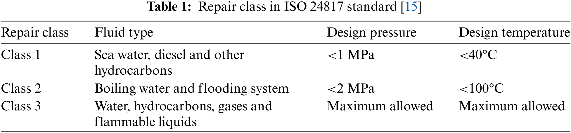
The composite reparation technology has also disadvantages related to the mechanical properties of the composite and to technical limits gives a representation of the possible damages that can occur due to the use of this technique. ISO 24817 standard [15] shows the defective layering of the composite, which is one of the major technical issues of this method. This issue may often be caused by an uneven distribution of stress and a subsequent increase of the internal pressure in the composite layers. In one of defects, it is shown the damages caused by external shocks to composites reinforced with glass and carbon fibers, respectively. Also, there are other defects that they illustrate the long-term behavior of fiber reinforced composites: their mechanical properties weaken over time and, as a result, they become dry and brittle.
Noor et al. [6] studied the methods of repairing fluid transmission pipelines. For angled and elongated pipes, pre-cured layered, flexible wet lay-up, pre-impregnated, split composite sleeve and flexible tape systems were used, which hardens in the final stage after curing. 73% cheaper than replacing the damaged section of the steel pipe completely and 24% cheaper than welded steel sleeve repairs. Mazurkiewicz et al. [12] investigated a metal pipe under internal pressure that was damaged by an excavator tooth, both numerically and experimentally. It examined the corrosion response of the damaged pipe as well as of the tube after the repair. The corroded pipe was reinforced with filler material and then repaired by an unidirectional glass fiber composite fabric. The analyses showed that a corrosion status to a depth of 60% of the pipe thickness reduces the pipe resistance up to 62%. Additionally, the results showed that when the composite reparation has 24 layers, it becomes even more resistant to corrosion than the metal pipe itself. Abd-Elhady et al. [16] performed numerical modeling of a metal pipe with an inclined crack. It was found that in a defective pipe under internal pressure, the crack grows along the original crack plane direction and, after the composite reparation, the internal pressure increases compared to the defective state. Moreover, the crack growth is prevented and ultimately the lifespan of the tube is increased. Barros et al. [17] experimentally investigated the effect of composite fabric on the corrosion of welded joints. They chose an ASTM2507 stainless steel tube, which is highly corrosion resistant and used an offshore platform for the tests. According to ASME B31.8S [18] standard, the minimum thickness of the repair layer for double-sided glass fiber fabric was calculated and installed on the corroded tank. It was observed that the repair done making use of composite screw is effective even for a damage as extended as 90% of the depth. Lim et al. [19] investigated the mechanical properties of steel and composite pipes through laboratory tests. The results showed that in pipes repaired with glass fiber composite, the critical pressure increases by 23% and causes a significant reduction of strain in the defect area.
Khan et al. [20] obtained numerical and experimental results by investigating the filler material. According to the ISO 24817 standard, an artificial defect was created on the pipe. This defective tube was then repaired with a nano-fluid filler amplifier and then with a nano-clay. Leong et al. [21] analyzed the effect of corrosion width on circumferential stress by means of numerical modelling, and repaired these corrosion damages with composites. Armentani et al. [22] studied the evolution of energy release rate for delamination defects in a composite panel numerically to evaluate the G distribution. While the study conducted by Canale et al. [23] does not directly address composite pipe repair methodologies, their investigation into moisture absorption in thick composite plates sheds light on potential concerns for long-term durability in underground and undersea applications. Ansari Sadrabadi et al. [24] performed a numerical and experimental investigation of a steel pipe repaired with a composite sleeve. It was found that the composite repairing system had almost eliminated the stress concentrations generated by a thickness reduction. Abd-Elhady et al. [25], by using numerical modelling on a metal pipe with an inclined crack, came to the conclusion that in a defective pipe under internal pressure, the crack grows in the original crack plane and after the repair with the use of composite, an increase of the internal pressure is caused with respect to the defective state. In addition, to suggest the continuation of research in the future, we can mention the optimization of the composite structure considering additive manufacturing technology [26].
Here are some general reasons why fiber composite materials are suggested for reinforcement:
• Enhanced stiffness and flexibility: Composites can be tailored to achieve specific stiffness and flexibility properties depending on the fiber orientation and matrix material. This allows for precise control over the mechanical response of the reinforced structure.
• Corrosion resistance: Unlike traditional metals, many fiber composite materials are highly resistant to corrosion, making them a valuable choice for applications exposed to harsh environments, like saltwater or chemicals.
• Fatigue resistance: Composites can withstand repeated stress cycles better than many other materials, leading to longer service life and reduced maintenance needs.
In this study, a composite fiber repair methodology is presented and analyzed with the help of both experiments and numerical simulations. The experimental tests are performed according to the relevant standards and codes, such as ASME PCC-2, ASME B31.8S, ASME B31.4, ISO 24817 and ASME B31.G. Some aspects of the problem are also addressed numerically by means of the finite element method.
In the present study, a steel pipe for the transportation of fluids, designed according to API 5L A106 Gr.B specifications, has been investigated. The pipe has an outer diameter of 88.9 mm (nominal 3 inches), a thickness of 5.5 mm and a length of 500 mm. Different caps configurations exist to close the two ends of the pipe. The hemispherical cap is characterized by a higher-pressure tolerance and can withstand an average pressure of up to about 2 times the elliptical cap of the same thickness. It has been well established by researchers that the best cap shape for a pressure vessel is hemispherical. Thus, two hemispherical caps were chosen and welded to the metal pipes using the argon welding technique.
The mechanical properties of the pipe including yield strength, ultimate strength and module of elasticity were obtained by preliminary tests performed according to the ASTM E8/E8M standards. The stress-strain diagram of a sample of pipe material with the specifications mentioned in Fig. 1 is shown in Fig. 2. To mitigate the statistical dispersion, the tensile tests were performed 4 times and the mechanical properties were calculated as average of the preliminary test results. An image of the test can be observed in Fig. 3.
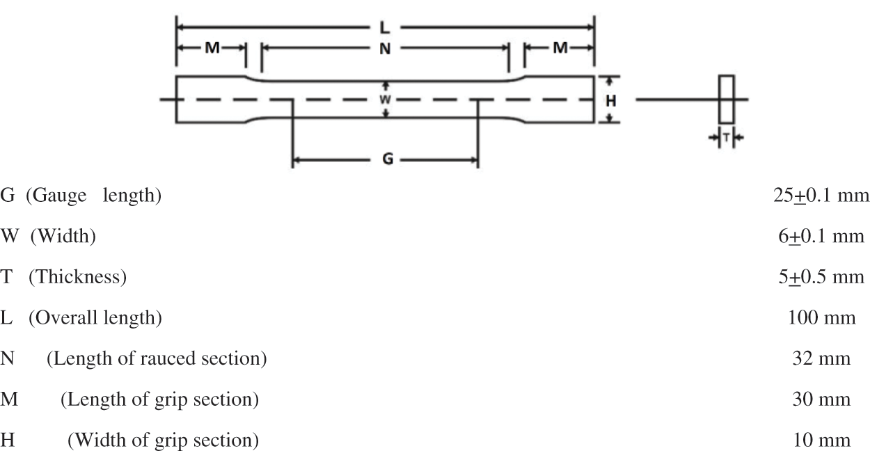
Figure 1: Sample size for tensile test
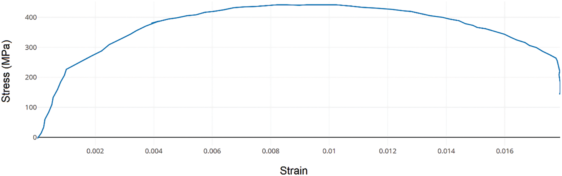
Figure 2: Stress-strain diagram of tensile test
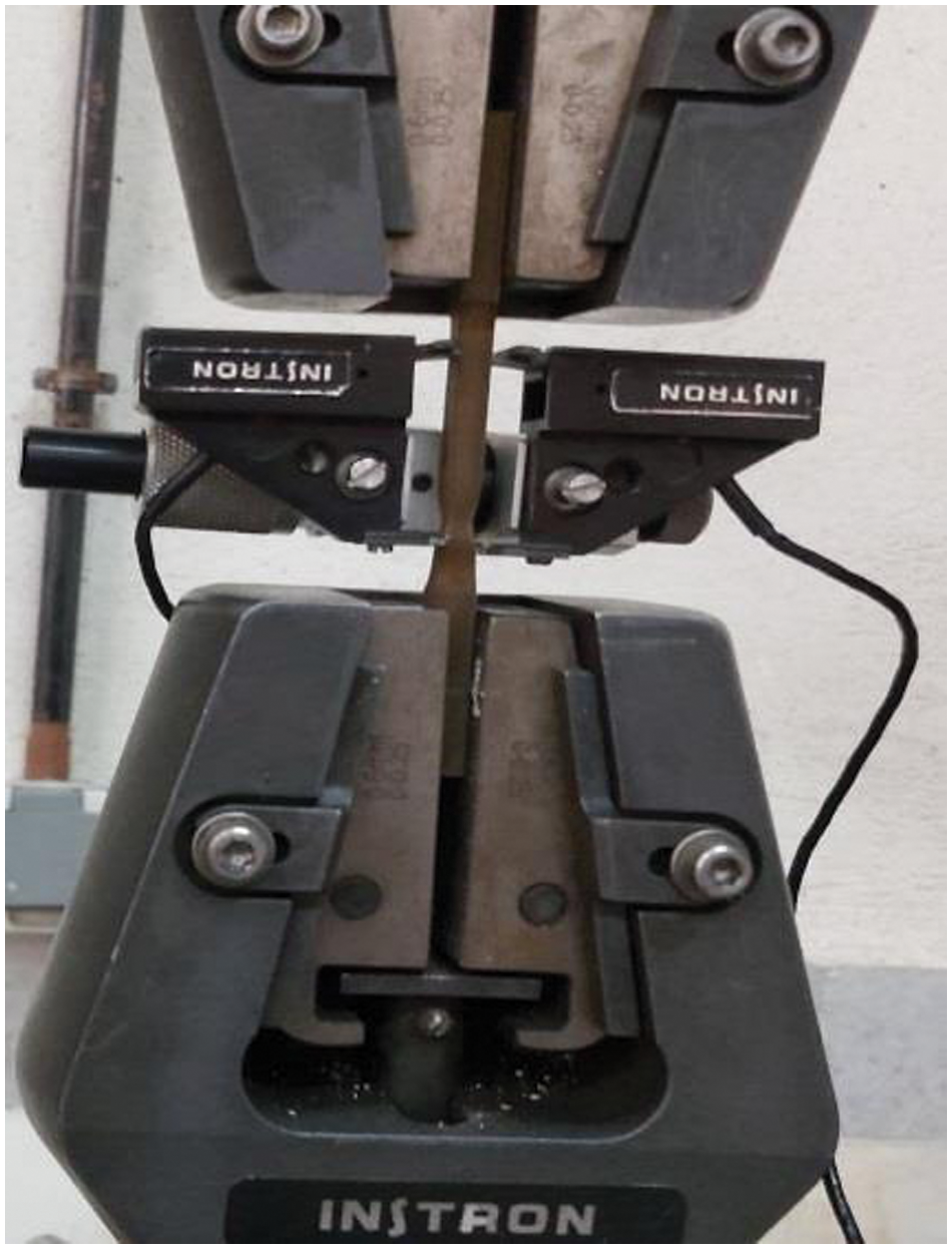
Figure 3: Tensile test on the sample
The experimental tests were performed by means of an electric hydraulic pump which is responsible for the pressure supply. The machine is capable of a maximum pressure of
During the first phase of the experiment, the intact vessel was connected to the hydraulic device and the internal pressure was increased. In the second phase, a defect was created on the outer surface of the pipe. The defect was designed according to the ASME PCC-2 [27] standard with a depth of 70% of the thickness. In Fig. 4a, sketch of the cavity geometry is shown. Also, an image of the defect can be seen in Fig. 5.
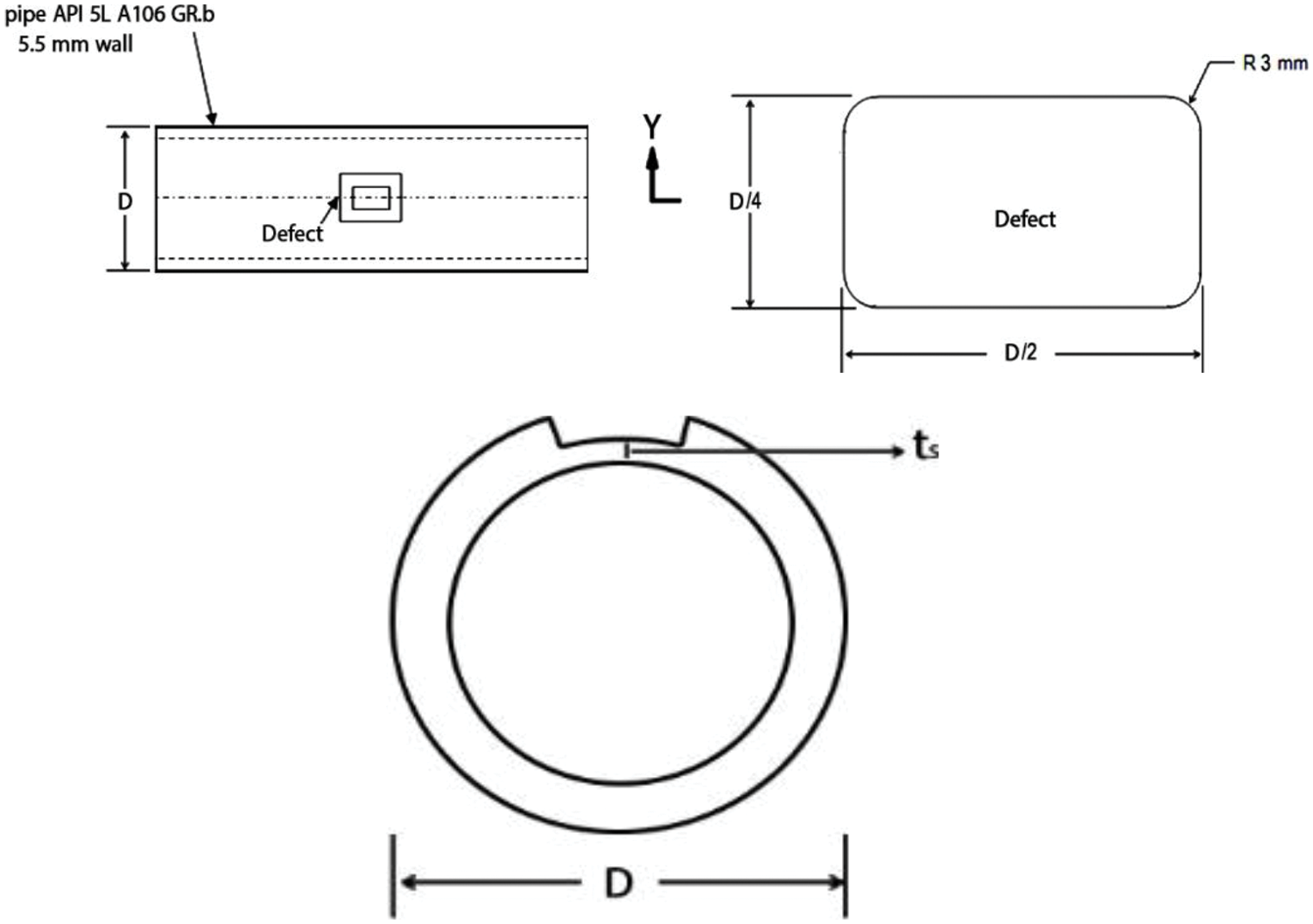
Figure 4: Defective pipe design
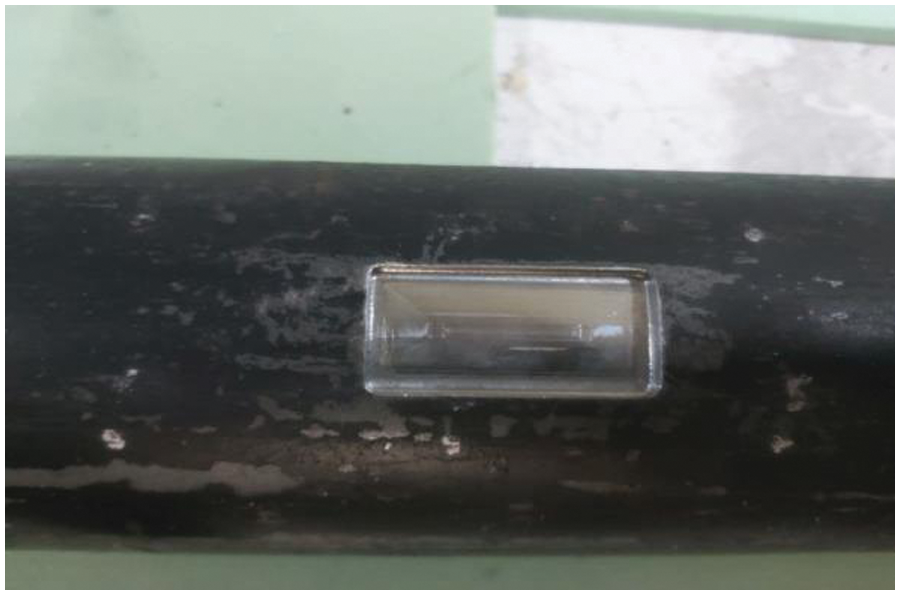
Figure 5: Defect created on the tank
Under testing conditions, a local increase of pressure is experienced by the vessel in the area surrounding the cavity due to the presence of the defect in the tank wall. This local increase of pressure leads to an increase in the local strain and eventually to a concentration of stress in this region with respect to the intact vessel test.
In order to measure the strain and the stress accordingly, the tank was equipped with strain gauges, as shown in Fig. 6. These were positioned on the outer skin of the pressurized tank and connected to a graphical user interface system. In this way, it was possible to monitor and register the stress level in the tank thickness in real-time during the experiments. According to the coordinates system of Fig. 6, the axial strain gauge A and the circumferential one B are positioned in the critical region near the defect, and the peripheral strain C is located at a distance of 70 mm from the defect, along the axial direction.
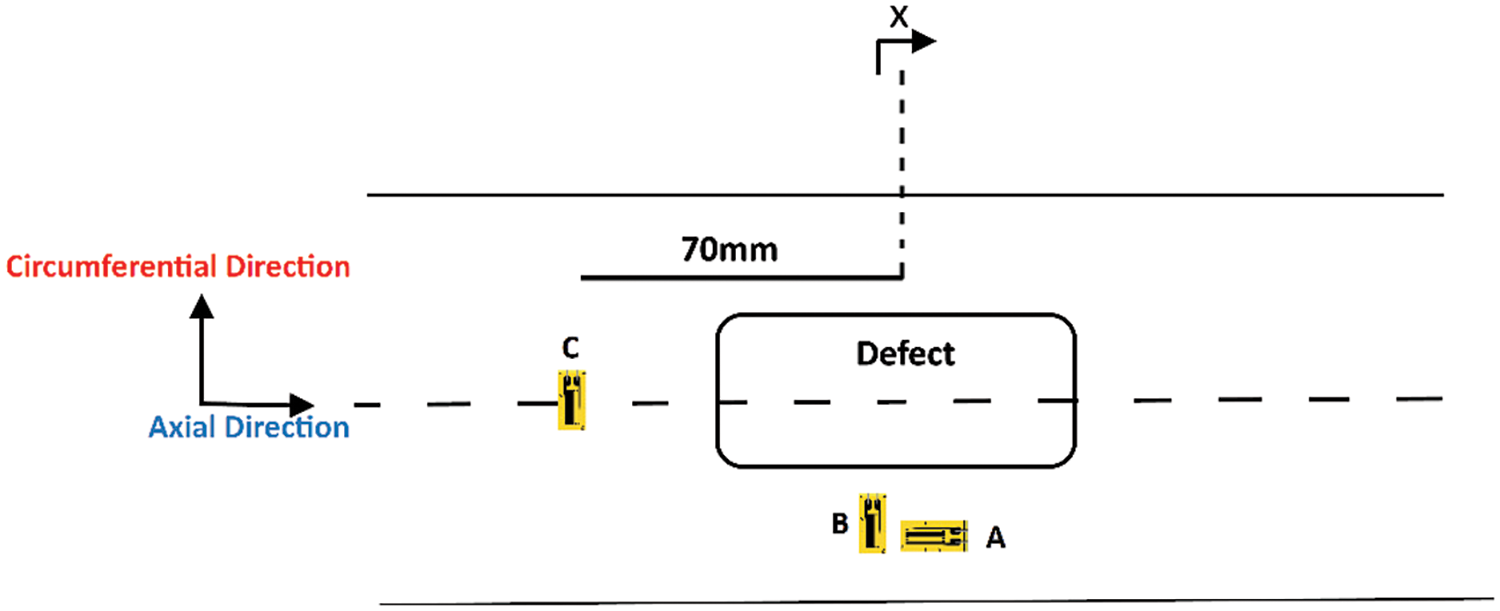
Figure 6: Strain gauge coordinates on the defective tank
Fig. 7 is a schematic representation of the experimental test rig. The tank is equipped with strain gauges which, in turn, are connected to the Data Logger through soldered wires. The tank is joined with the high-pressure hose of the hydraulic pump and filled with hydraulic oil. With this apparatus, it is possible to monitor the internal pressure of the oil as well as the stress and strain level of the tank on display. Fig. 8 shows the defective tank under test, fully equipped with the strain and pressure gauges.
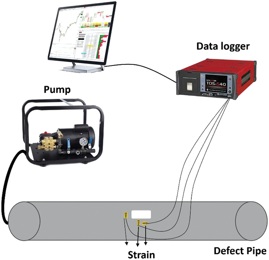
Figure 7: Schematic diagram of a defective pipe test
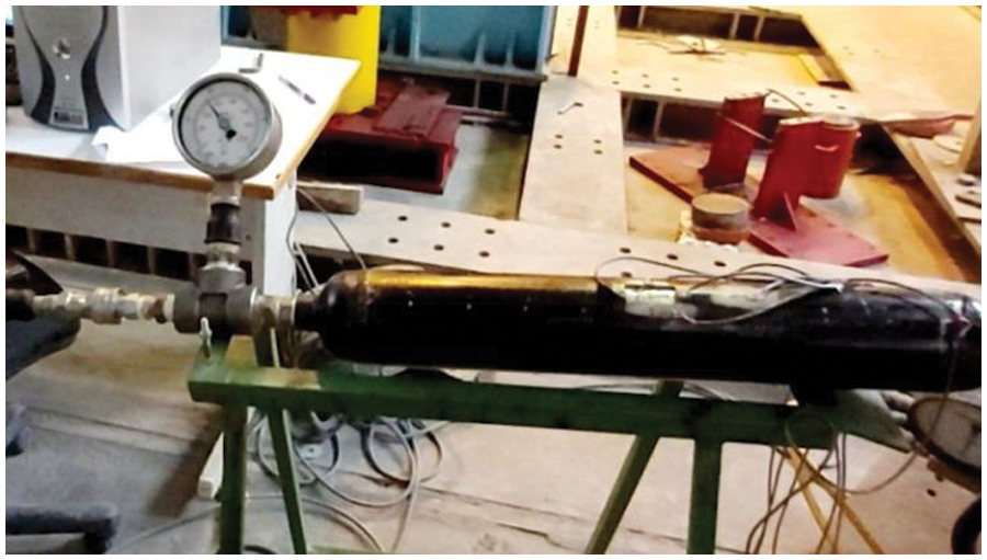
Figure 8: Defective pipe test
Fig. 9 shows the strain evolution during the test measured by the three strain gauges in the defective pipe. In areas close to the defect, due to geometric changes and non-uniformity of the area, the axial strain (gauge A) is higher than the peripheral strain (gauge B). In fact, the axial gauge detects tensile deformation whereas the circumferential one reveals a compressive deformation. The peripheral strain gauge positioned in C is stretched due to its distance from the defect.
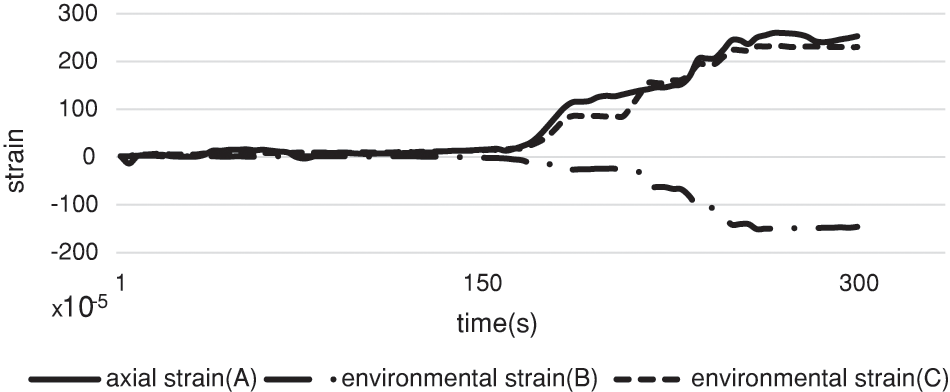
Figure 9: Axial and environmental strain measured during the experiment
As shown in Figs. 10–12, to repair the defective tank and reduce the strain and concentration of stress in the cavity area, first, the inside of the defect is filled with filler material and then the metal tank is repaired by screwing the composite fabric reinforced with glass fibers. Generally, the filler material is flexible and has a high compressive strength which enables the transmission of the internal stress from the pipe to the composite. In this study, for the first time, it was used as filler material, a mixture of resin and hardener. Next, the surface of the pipe and the composite layers are impregnated with the hardened resin mixture. Thereafter, the layered composite fabric is wrapped onto the defective pipe to reach the minimum thickness of the repair layer as designed by ISO-standards [15] and following the prescriptions of several ASME-standards [18,27–32].
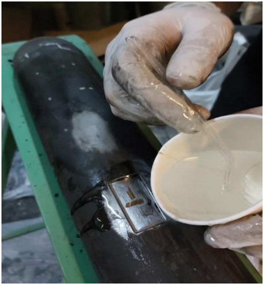
Figure 10: Filling the artificial defect with hardener resin
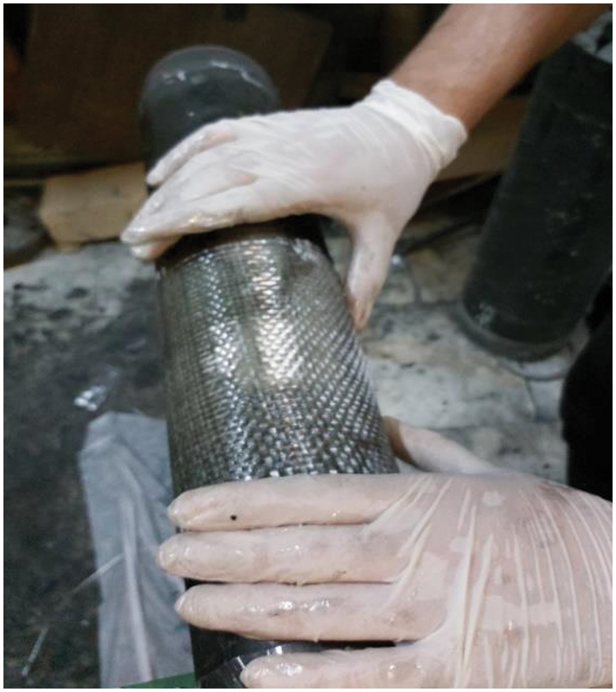
Figure 11: Impregnation of composite layers with resin
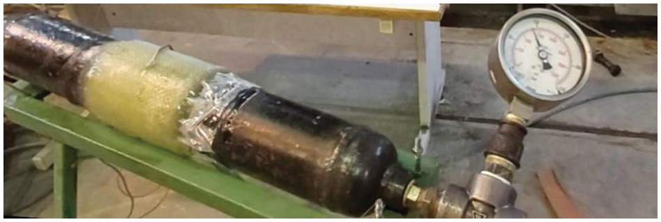
Figure 12: Pipe repaired with Glass Fiber Reinforced Polymer (GFRP) under internal pressure
Once the installation of the composite screw was finished, a perimeter strain gauge was attached to the composite fabric as shown in Fig. 13. This was needed to monitor the strain in the repaired area during the final test under the action of the internal pressure.
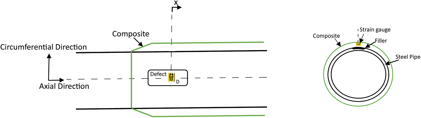
Figure 13: Strain gauge coordinates on the repaired tank
Fig. 14 is a diagram of the circumferential strain evolution of the repaired pipe. The hoop strain was tensile throughout the duration of the experiment, and it presented an increasing trend with the internal pressure. As the defect is repaired, the discontinuities are removed and the cylindrical relations between longitudinal and hoop strain are re-established with the hoop strain being greater than the axial one.
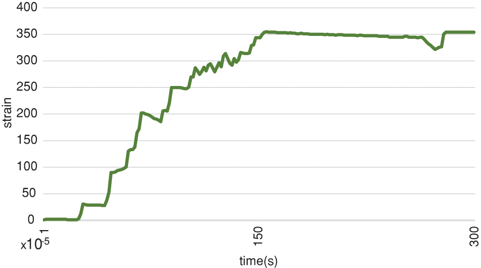
Figure 14: Peripheral strain diagram of the repaired tank
The maximum oil pressure applied in the three experiments was calculated by means of the von Mises yield criterion in order to not exceed the yield strength of the material. In a point of a cylindrical pressure vessel, the von Mises formula writes:
Given that the tank is thin-walled (
The latter equation suggests a maximum allowable internal pressure of
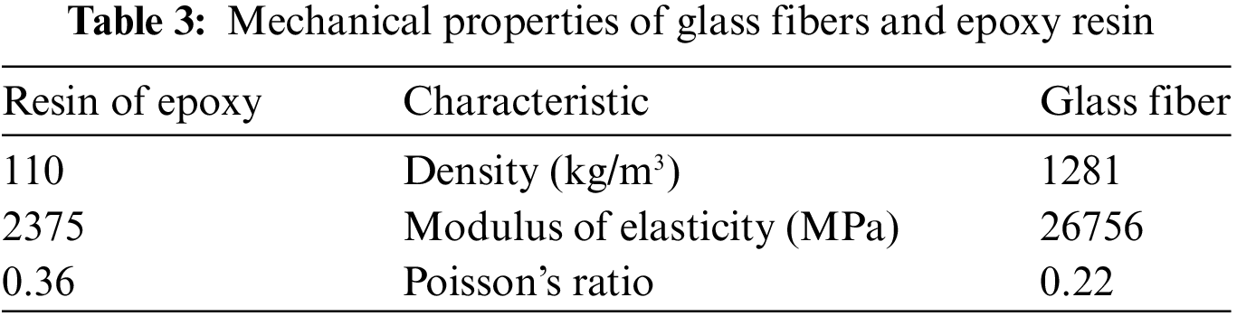
Knowing the mechanical properties for fabric and resin, the corresponding properties of each repair layer could be calculated according to micromechanical relationships reported below [33]:
In these expressions,
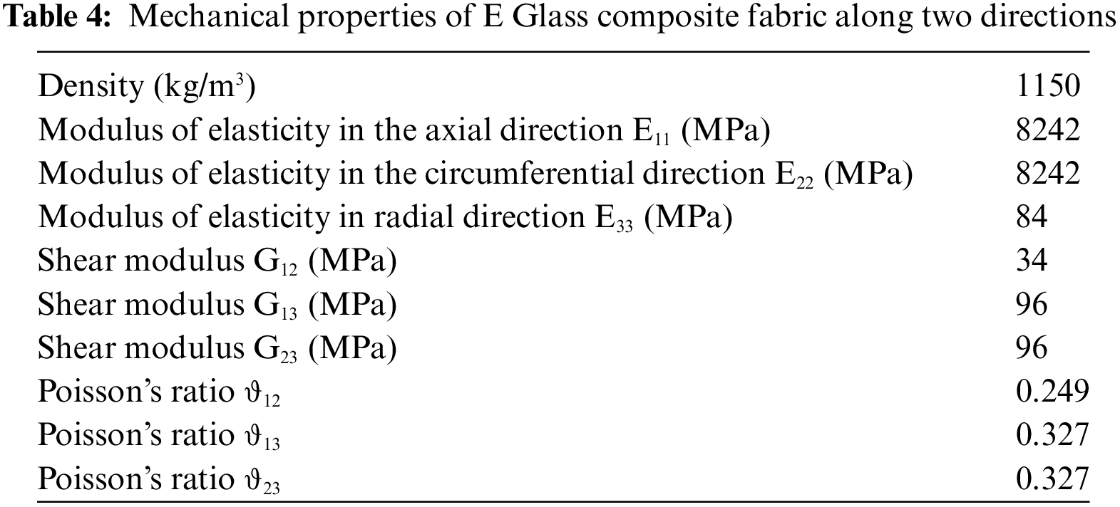
In the present study, the E-Glass composite fabric fibers were selected because of their high strength, corrosion resistance and good torsional stiffness. Fiberglass composite is, due to its considerably good mechanical properties and its low cost, one of the most widely used composites available. The bidirectional mechanical properties of the composite with glass fibers measured experimentally are given in Table 4. These values were used as material parameter for the numerical analyses.
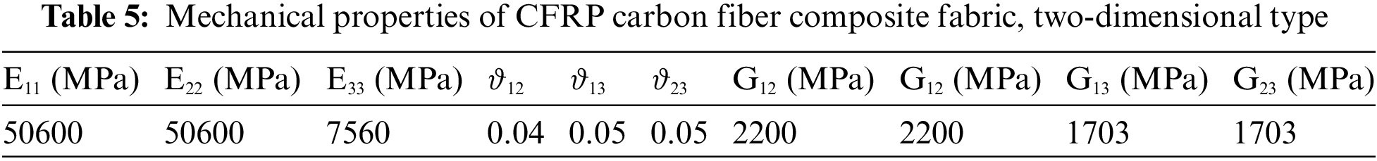
To observe the effect of the type of fiber in repairing defective pipes, the numerical model of the defective pipe was repaired with carbon fiber double-sided composite fabric (CFRP). The most important mechanical properties of carbon fiber composite are the very high tensile strength, the low weight and the high resistance in chemical and corrosive environments. The main mechanical properties of carbon fiber composite are reported in Table 5.
3.1 Calculation of the Minimum Thickness of the Repair Composite
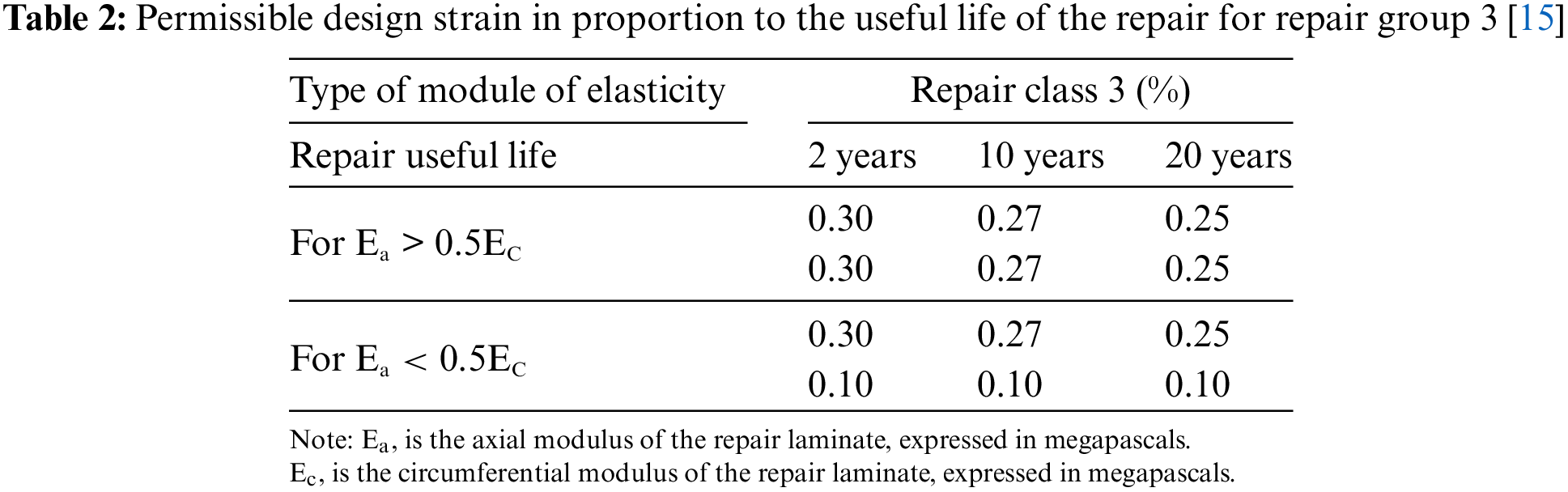
The minimum thickness of the composite screw on the tank is calculated according to ISO 24817 [15]. In the equations reported underneath,
3.2 Calculation of Repair Composite Length
The minimum amount of repair length of the composite screw was calculated according to ISO 24817 standard in [15]. The following equations were used to compute the minimum repair length and it resulted to be
The pipe sample used for the tests was modelled by means of the finite element software ABAQUS as shown in Fig. 15. First, the cylinder geometry and the two hemispherical caps were created and then merged together with a tie constraint. The mechanical properties were defined according to Table 3 and an internal pressure of
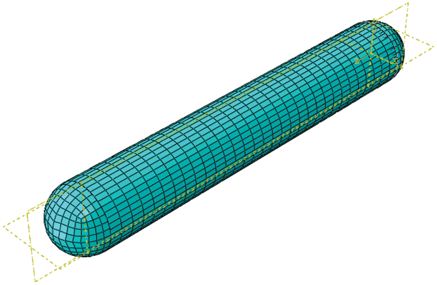
Figure 15: Pipe modeling in the mesh module
To simulate the defect in the tank, 70% of the pipe wall thickness, located at the middle pipe length as shown in Fig. 16, was removed in accordance with ISO 24817 standard. In accordance with the experimental test conditions, the internal pressure was set to
Figure 16: Tank corrosion in modeling
The geometry of the specimen was meshed using second-order hexahedral elements (C3D20). The final mesh was obtained after a convergence analysis, made on the number of elements required in the area surrounding the defect. The converged mesh was made up of 7581 20-node brick elements of type C3D20, as shown in Fig. 17.
Figure 17: Convergence of the element at the location of the pipe defect
In Fig. 18a, comparison of the von Mises stress distribution along the pipe length is presented for both intact and defective pipe. The portion of pipe under analysis is the area surrounding the defect along the axial direction. It can be seen that within the area of thickness reduction, the stress remarkably increases (by a factor of 4) with respect to the intact vessel. The area directly close to the outer edge of the defect faces a rapid reduction of the stress due to the sharp geometry change. Thus, the presence of the defect has only a local effect as the stress level reaches the non-defective stress level.
Figure 18: Comparison of stress diagrams in healthy and defective pipes
The repair was modelled by means of the finite element software as well as shown in Figs. 19 and 20. The filler resin was inserted in the defect and assembled through a tie-type constraint to the defective pipe geometry. On top of this, a layer of GFRP composite fabric, having a thickness calculated according to Eqs. (17) and (18), was modelled and tied to the global model. The mechanical properties of both the resin and the composite layer were defined according to Tables 3 and 5. The diagram of Fig. 21 shows the von Mises stress trend along the pipe’s axial direction for all the configuration under analysis: intact pipe, defective pipe, pipe reinforced with filler resin and pipe repaired with GFRP composite fabric. The diagram shows that the stress concentration decreases by 4% as consequence of the filler resin reinforcement; the reduction increases to 22% after the GFRP composite fabric insertion. A further enhancement of the repaired vessel is shown in Fig. 22. Here, it is visible the circumferential strain reduction by 62% with respect to the pipe configuration before the repair.
Figure 19: Placing the filler in the defect of the pipe
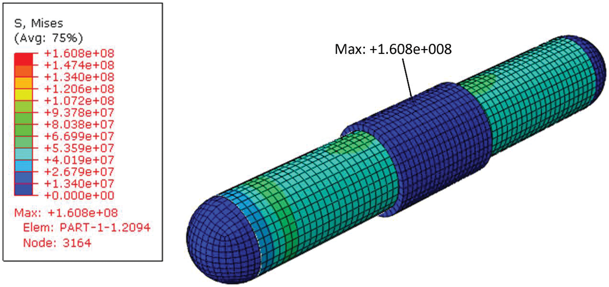
Figure 20: Final view of repairing a defective pipe with the help of composite in mesh module
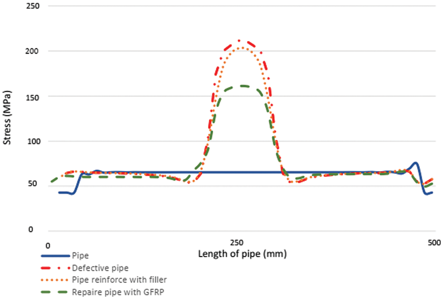
Figure 21: Comparison diagram of stress distribution in healthy, defective, filler-reinforced and composite-repaired pipe
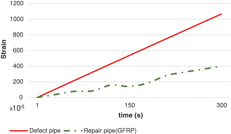
Figure 22: Peripheral strain diagram in the pipe before and after repair
In order to assess the effect caused by the use of a different woven composite fabric, it was created a numerical modelled of the pipe having an outer repair layer made of CFRP fibers instead of the GFRP one. The calculation of the minimum thickness of the layer required, performed as per Eq. (14), showed that the CFRP layer is more than 50% thinner than the GFRP layer. With the CFRP configuration, the simulation results showed a 12.5% reduction of the von Mises peak stress with respect to the GFRP one; in addition, also the circumferential strain presented a reduction of 25% in the supplementary configuration. The simulation image and its results can be seen in Figs. 23–27. In addition, a comparison of experimental and numerical strain of defective pipe and repaired pipe is shown in Table 6.
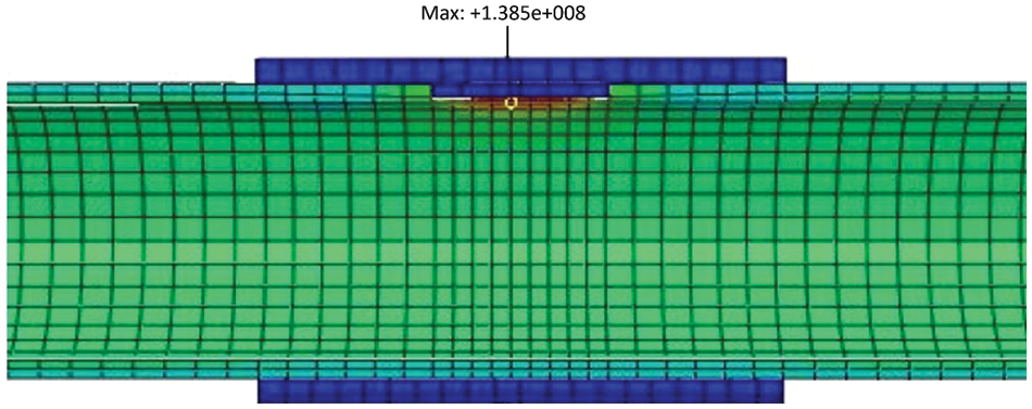
Figure 23: Stress in a pipe repaired with CFRP composite
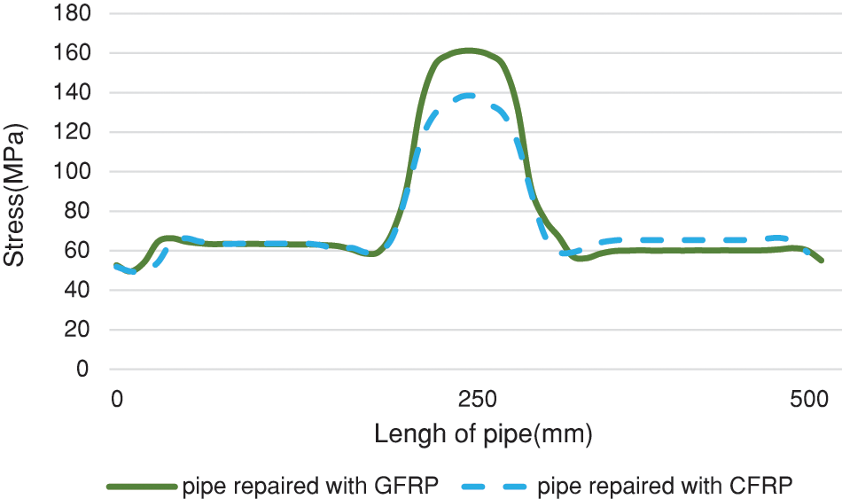
Figure 24: Comparison diagram of stress distribution in a pipe repaired by GFRP and CFRP composite fibers
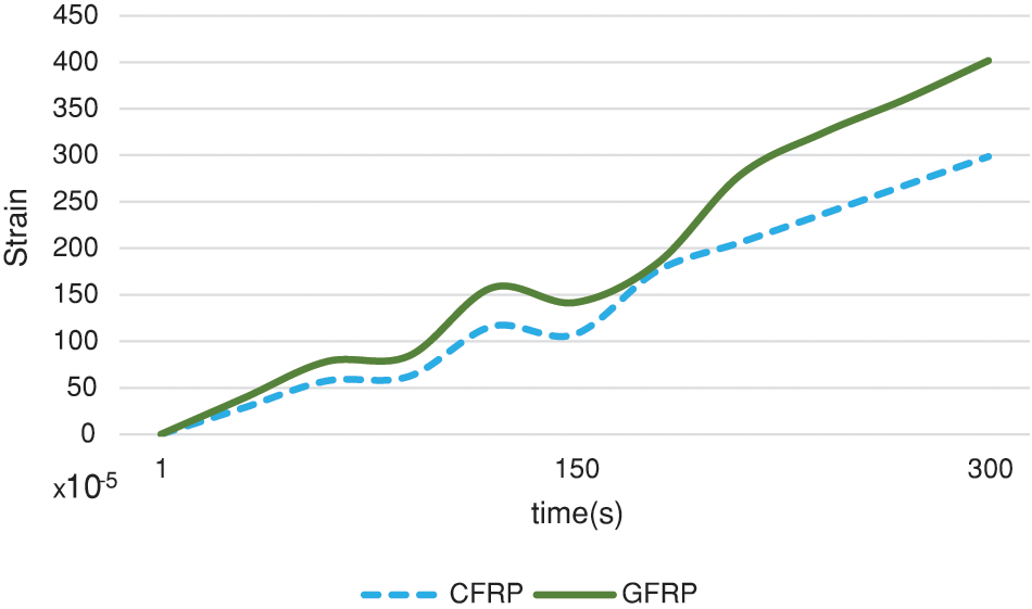
Figure 25: Comparison diagram of circumferential strain in a tank repaired with the help of composite with GFRP and CFRP fibers
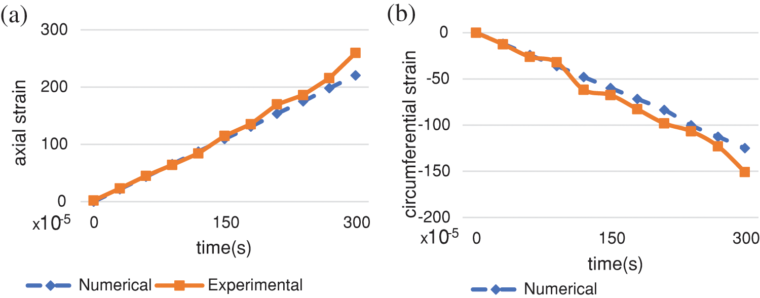
Figure 26: Comparison of experimental and numerical strain of defective pipe: (a) axial strain at point A (b) circumferential strain at point B
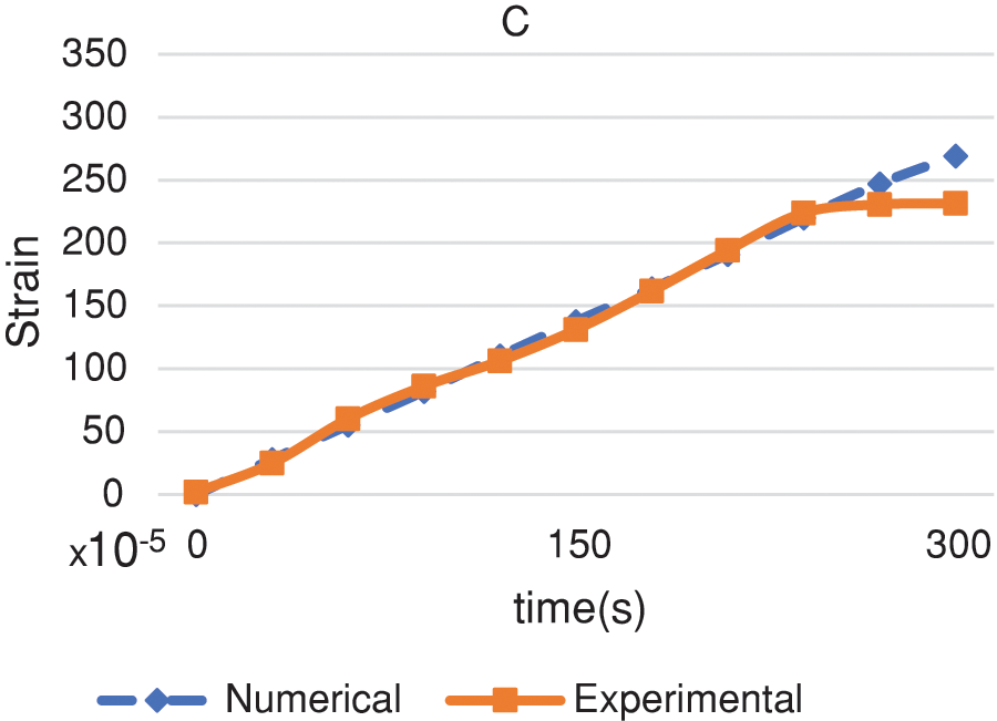
Figure 27: Comparison of experimental and numerical circumferential strain of defective pipe at point C
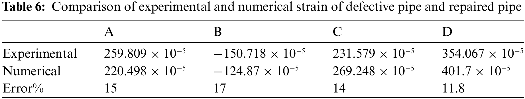
As can be observed from the diagram of Fig. 28, there is a very precise agreement between numerical and experimental results of the circumferential strain. In fact, the maximum difference detected, always at the highest-pressure levels, was 11.8%. This could be explained by the fact that the reparation reduces the non-linarites related to the sharp variation of the geometry and as a consequence attenuate the stress pick; this secondary effect is not detected by the FE-analysis of the numerical model. An other explanation is that the high level of the internal pressure caused a fluctuations in the strain gauges measurement.
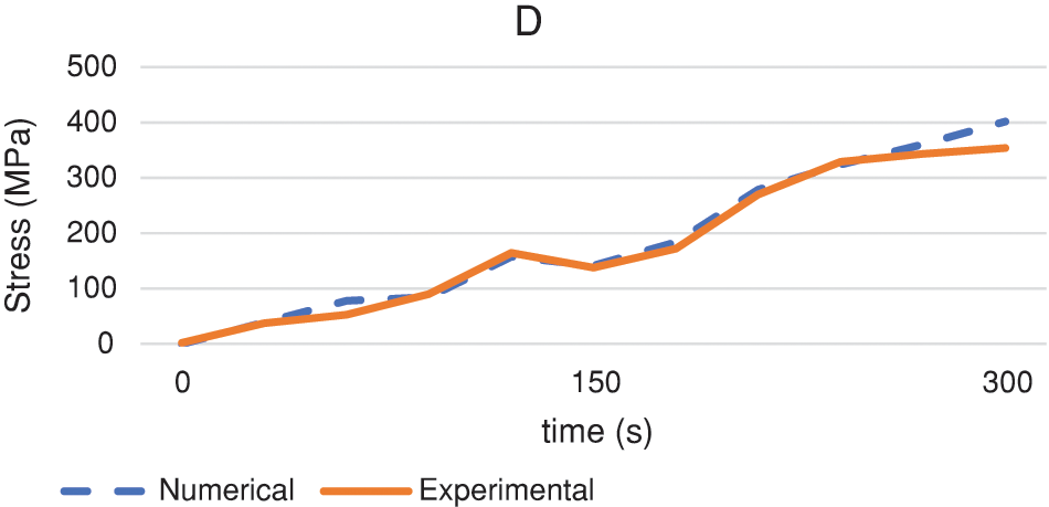
Figure 28: Comparison of experimental and numerical stress of repaired pipe at point D
In the experimental tests, the defective and repaired pipe were equipped with strain gauges to monitor the strain in the surrounding area as a function of the internal pressure applied to the pipe. Analogously to the tests, the same approach was followed for the numerical simulations. Consequently, the numerical results were compared with the test data to validate the numerical model. The results demonstrate quantitatively that the corroded pipeline reacquired its lifespan; in fact, it regained the resistance to internal pressure, flow capacity and deformation requirements almost as its pre-repair state.
The approach presented in this study demonstrates the potential of GFRP and CFRP composite fabrics for effectively repairing defective steel pipes. This method offers several advantages, including minimal disruption to existing infrastructure, relatively quick and cost-effective installation compared to traditional repair techniques, and improved structural integrity of the pipe by alleviating stress and strain concentrations. Further research could explore the application of this method to different types of pipe materials, defect geometries, and loading conditions. Investigating the long-term durability and fatigue performance of the repairs would also be crucial for ensuring their reliability and longevity in real-world applications.
The results of the finite element analyses demonstrate the substantial improvement in structural integrity achieved through the combined application of filler resin and GFRP composite fabric. As shown in Fig. 21, the stress pick is reduced by 4% due to the filler resin reinforcement. This reduction further increases to 22% following the GFRP composite fabric application. Fig. 22 further illustrates the effectiveness of the repair by showing a 62% reduction in circumferential strain compared to the unrepaired pipe.
Figs. 26 and 27 report the axial and circumferential strain comparison between tests data and numerical results. Due to the defect’s geometry, the axial gauge A and the circumferential one C detect a tensile and increasing trend during the experiment, whereas a compressive and downward trend occurs for the circumferential strain gauge B. The numerical analyses were able to reproduce the experiments both in terms of strain values and trend. The numerical-experimental agreement is complete in the initial part of the test whereas, during the second half of the experiment, a mismatch arises. The maximum error between experimental data and numerical results was detected by the circumferential strain gauge B, corresponding to a value of 17% as per Table 6. Also, in Fig. 26, the correspondence in the axial strain diagram, gauge B, between experiments and numerical analyses is spotless over the first 100 s of the test. According to the coordinates of the strain gauge in Fig. 27, it can be seen that the peripheral strain C is located at a distance of 70 mm from the center of the defect. As shown in Fig. 27, due to the distance of this strain gauge from the defect location-the peripheral strain C was located at a distance of 70 mm from the center of the defect- the nonlinear effects and deformation are less evident. From the beginning to the time of 250 s, the two curves, experimental and numerical, match entirely, but in the end of the test, when the internal pressure was 90 bar, a maximum difference of 14% arises.
The present study shows the superb capabilities of composite repair. Nevertheless further tests are needed to assess its endurance resistance. The long-term exposure to environmental stressors, such as fluctuating pressure and fatigue originated from cyclic loads demands careful consideration. Implementing a dedicated monitoring program, alongside routine maintenance schedules tailored for the unique characteristics of the repaired pipeline, will ensure its continued operational life.
In this study, a new method was proposed to repair defective steel pipelines in accordance with ISO 24817 standard (glass fiber composite thread). From the analysis of the comparison between numerical simulations and experiments, the following conclusions are drawn:
• By creating an axial defect to a depth of 70% of the thickness on the reservoir cylinder, the stress concentration is increased more than 3 times and the maximum stress is achieved at the inner edges of the defect.
• In the area surrounding the defect, the geometrical discontinuity makes the axial strain being higher than the circumferential one. This trend is inverted as the axial strain gauge is moved away from the defect location. Moreover, the presence of the defect causes a compressive circumferential strain and a tensile axial strain.
• The reparation with only filler material, a compound of resin and hardener, reduces the stress concentration by 4% with respect to the defective pipe. The addition of a GFRP composite fabric layer reduces the maximum von Mises stress by 22% and the circumferential strain by 62%. Furthermore, it was proven that the use of a different composite fiber layer has an influence on the repair. In fact, the use of a Carbon Fiber-Reinforced plastic (CFRP) fiber, in place of GFRP fiber, was beneficial not only in terms of thickness (more than 50%-layer reduction) but also in terms of local stress and strain reduction and global redistribution.
Acknowledgement: None.
Funding Statement: The authors received no specific funding for this study.
Author Contributions: Conceptualization, visualization, S.A.S.; methodology, G.H.R.; software, S.M.R.A.; validation, investigation, writing—original draft preparation, S.M.R.A.; resources, L.F.; writing—review and editing, H.A., D.A. and G.S.; supervision, S.A.S. and G.H.R.; project administration, S.A.S.
Availability of Data and Materials: The data that support the findings of this study are available upon reasonable request.
Conflicts of Interest: The authors declare that they have no conflicts of interest to report regarding the present study.
References
1. Ansari Sadrabadi, S., Nayebi, A., Rahimi, G. (2016). Behavior of FGM spherical vessels under internal pressure and temperature difference. Amirkabir (Journal of Science and Technology), 47(2), 43–50. https://doi.org/10.22060/mej.2016.375 [Google Scholar] [CrossRef]
2. Efraim, E., Eisenberger, M. (2006). Exact vibration frequencies of segmented axisymmetric shells. Thin-Walled Structures, 44(3), 281–289. https://doi.org/10.1016/j.tws.2006.03.006 [Google Scholar] [CrossRef]
3. Mally, T. S., Johnston, A. L., Chann, M., Walker, R. H., Keller, M. W. (2013). Performance of a carbon-fiber/epoxy composite for the underwater repair of pressure equipment. Composite Structures, 100, 542–547. https://doi.org/10.1016/j.compstruct.2012.12.015 [Google Scholar] [CrossRef]
4. Rohem, N. R., Pacheco, L. J., Budhe, S., Banea, M. D., Sampaio, E. M. et al. (2016). Development and qualification of a new polymeric matrix laminated composite for pipe repair. Composite Structures, 152, 737–745. https://doi.org/10.1016/j.compstruct.2016.05.091 [Google Scholar] [CrossRef]
5. Abdelghany, A., Taha, I., Ebeid, S. (2016). Failure prediction of fiber reinforced polymer pipes using FEA. International Journal of Engineering and Technical Research, 4, 115–120. [Google Scholar]
6. Noor, N., Azraai, S. N. A., Lim, K. S., Yahaya, N. (2015). An overview of corroded pipe repair techniques using composite materials. International Journal of Chemical, Molecular, Nuclear, Materials and Metallurgical Engineering, 10, 19–25. [Google Scholar]
7. Mehditabar, A., Razmkhah, S., Sadrabadi, S. A., Peng, X., Yuan, S. et al. (2023). Three-dimensional thermoelastic analysis of a functionally graded truncated conical shell with piezoelectric layers. International Journal of Computational Materials Science and Engineering, 12(3), 2350003. https://doi.org/10.1142/S2047684123500033 [Google Scholar] [CrossRef]
8. Mehditabar, A., Ansari Sadrabadi, S., Walker, J. (2023). Thermal buckling analysis of a functionally graded microshell based on higher-order shear deformation and modified couple stress theories. Mechanics Based Design of Structures and Machines, 51(5), 2812–2830. https://doi.org/10.1080/15397734.2021.1908145 [Google Scholar] [CrossRef]
9. Mehditabar, A., Ansari Sadrabadi, S., Sepe, R., Armentani, E., Walker, J. et al. (2020). Influences of material variations of functionally graded pipe on the bree diagram. Applied Sciences, 10(8), 2936. https://doi.org/10.3390/app10082936 [Google Scholar] [CrossRef]
10. Sadrabadi, S. A., Rahimi, G. H. (2014). Yield onset of thermo-mechanical loading of FGM thick walled cylindrical pressure vessels. International Journal of Mechanical, Aerospace, Industrial and Mechatronics Engineering, 8(7), 1317–1321. https://doi.org/10.5281/zenodo.1096845 [Google Scholar] [CrossRef]
11. Ansari Sadrabadi, S., Rahimi, G. H. (2016). Elasto-plastic behavior analysis and yield onset in FG cylindrical tubes under mechanical and thermal loads. Mdrsjrns, 16(2), 159–166. [Google Scholar]
12. Baranowski, P., Mazurkiewicz, Ł., Małachowski, J., Tomaszewski, M., Yukhymets, P. (2017). Performance of steel pipe reinforced with composite sleave. Composite Structures, 183, 199–211. https://doi.org/10.1016/j.compstruct.2017.02.032 [Google Scholar] [CrossRef]
13. Brenner, N. (2022). Nord stream repair no easy matter. Energy Intelligence. Noah Brenner, London. https://www.energyintel.com/00000183-85f4-d9e7-a3fb-cdf6c6270000 (accessed on 10/03/2023). [Google Scholar]
14. Saeed, N., Ronagh, H. R. (2015). Design of fibre-reinforced polymer overwraps for pipe pressure. In: Rehabilitation of pipelines using fiber-reinforced polymer (FRP) composites, pp. 211–223. Cambridge, UK, Elsevier-Hanley and Belfus Inc. https://doi.org/10.1016/B978-0-85709-684-5.00010-2 [Google Scholar] [CrossRef]
15. ISO (2017). ISO 24817: Petroleum, petrochemical and natural gas industries—Composite repairs for pipework—Qualification and design, installation, testing and inspection. https://www.iso.org/standard/70958.html (accessed on 10/03/2023). [Google Scholar]
16. Abd-Elhady, A. A., Sallam, H. -D. M., Mubaraki, M. A. (2017). Failure analysis of composite repaired pipelines with an inclined crack under static internal pressure. Procedia Structural Integrity, 5, 123–130. https://doi.org/10.1016/j.prostr.2017.07.077 [Google Scholar] [CrossRef]
17. de Barros, S., Budhe, S., Banea, M. D., Rohen, N. R., Sampaio, E. M. et al. (2018). An assessment of composite repair system in offshore platform for corroded circumferential welds in super duplex steel pipe. Frattura ed Integrità Strutturale, 12(44), 151–160. [Google Scholar]
18. ASME (2022). B31.8S: Managing system integrity of gas pipelines. https://www.asme.org/codes-standards/find-codes-standards/b31-8s-managing-system-integrity-gas-pipelines/2022/drm-enabled-pdf (accessed on 10/03/2023). [Google Scholar]
19. Lim, K. S., Azraai, S. N. A., Yahaya, N., Noor, N. M., Zardasti, L. et al. (2019). Behaviour of steel pipelines with composite repairs analysed using experimental and numerical approaches. Thin-Walled Structures, 139, 321–333. [Google Scholar]
20. Chandra Khan, V., Balaganesan, G., Kumar Pradhan, A., Sivakumar, M. S. (2017). Nanofillers reinforced polymer composites wrap to repair corroded steel pipe lines. Journal of Pressure Vessel Technology. https://doi.org/10.1115/1.4036534 [Google Scholar] [CrossRef]
21. Leong, K. E., Lim, K. S., Sulaiman, A. S., Chin, S. C., Yahaya, N. (2020). Effect of defect width upon burst capacity of composite repaired pipe. IOP Conference Series: Materials Science and Engineering, vol. 712, 012018. [Google Scholar]
22. Armentani, E., Caputo, F., Esposito, R., Godono, G. (2004). Evaluation of energy release rate for delamination defects at the skin/stringer interface of a stiffened composite panel. Engineering Fracture Mechanics, 71(4), 885–895. https://doi.org/10.1016/S0013-7944(03)00045-6 [Google Scholar] [CrossRef]
23. Canale, G., Kinawy, M., Sathujoda, P., Maligno, A., Citarella, R. G. (2020). Moisture absorption in thick composite plates: Modelling and experiments. Multidiscipline Modeling in Materials and Structures, 16(3), 439–447. [Google Scholar]
24. Ansari Sadrabadi, S., Dadashi, A., Yuan, S., Giannella, V., Citarella, R. (2022). Experimental-numerical investigation of a steel pipe repaired with a composite sleeve. Applied Sciences, 12(15), 7536. https://doi.org/10.3390/app12157536 [Google Scholar] [CrossRef]
25. Abd-Elhady, A. A., Sallam, H. E. D. M., Alarifi, I. M., Malik, R. A., El-Bagory, T. M. (2020). Investigation of fatigue crack propagation in steel pipeline repaired by glass fiber reinforced polymer. Composite Structures, 242, 112189. [Google Scholar]
26. Toragay, O., Silva, D. F., Vinel, A., Shamsaei, N. (2022). Exact global optimization of frame structures for additive manufacturing. Structural and Multidisciplinary Optimization, 65(3), 97. https://doi.org/10.1007/s00158-022-03178-0 [Google Scholar] [CrossRef]
27. ASME (2022). PCC-2: Repair of pressure equipment and piping. https://www.asme.org/codes-standards/find-codes-standards/pcc-2-repair-pressure-equipment-piping (accessed on 10/03/2023). [Google Scholar]
28. The American Society of Mechanical Engineers (2012). ASME B31G-Manual for determining the remaining strength of corroded pipelines. https://www.asme.org/getmedia/7336b61b-5762-47ca-bdcb-8a4e0de6f162/33501.pdf (accessed on 10/03/2023). [Google Scholar]
29. ASME (2021). BPVC section VIII-rules for construction of pressure vessels division 1. https://www.asme.org/codes-standards/find-codes-standards/bpvc-viii-1-bpvc-section-viii-rules-construction-pressure-vessels-division-1/2023/print-book (accessed on 10/04/2023). [Google Scholar]
30. Peters, P. E. D. T., Ritter, E. R. (2019). ASME boiler and pressure vessel code section VIII, division 3: Example problem manual. https://www.asme.org/codes-standards/find-codes-standards/ptb-5-asme-section-viii-division-3-example-problem-manual (accessed on 10/04/2023). [Google Scholar]
31. ASME (2023). BPVC section II-materials-part D-properties-(Metric). https://www.asme.org/codes-standards/find-codes-standards/bpvc-iid-bpvc-section-ii-materials-part-d-properties-(1)/2023/print-book (accessed on 02/02/2023). [Google Scholar]
32. ASME (2022). B31.8: Gas transmission and distribution piping systems. https://www.asme.org/codes-standards/find-codes-standards/b31-8-gas-transmission-distribution-piping-systems (accessed on 10/04/2023). [Google Scholar]
33. Kaw, A. K. (2005). Mechanics of composite materials, 2nd edition. Boca Raton, CRC Press. https://doi.org/10.1201/9781420058291 [Google Scholar] [CrossRef]
Cite This Article
 Copyright © 2024 The Author(s). Published by Tech Science Press.
This work is licensed under a Creative Commons Attribution 4.0 International License , which permits unrestricted use, distribution, and reproduction in any medium, provided the original work is properly cited.
 Downloads
 Citation Tools