 Open Access
ARTICLE
Study on Chaotic Characteristics of the Friction Process between High Hardness Alloy Steel and Cemented Carbide under C60 Nanoparticle Fluid Lubrication
School of Aerospace Engineering, Xiamen University, Xiamen, 361005, China
* Corresponding Author: Bin Yao. Email:
(This article belongs to the Special Issue: Vibration Control and Utilization)
Computer Modeling in Engineering & Sciences 2024, 138(1), 525-550. https://doi.org/10.32604/cmes.2023.029675
Received 02 March 2023; Accepted 11 May 2023; Issue published 22 September 2023
Abstract
Friction and wear phenomenon is a complex nonlinear system, and it is also a significant problem in the process of metal cutting. In order to systematically analyze the friction and wear process of tool material-workpiece material friction pair in the cutting process of high hardness alloy steel under different lubrication conditions, the chaotic characteristics of friction process between high hardness alloy steel and cemented carbide under the lubrication C60 nano-particles fluid are studied based on the chaos theory. Firstly, the friction and wear experiments of the friction pair between high hardness alloy steel and cemented carbide tool are carried out based on the ring-block friction and wear tester, and the results of friction force signal in time domain and wear width are obtained. Then, the friction signals in time domain are processed and transformed based on phase space reconstruction and recurrence plot theory, and the recurrence plots of different experimental groups under different lubrication conditions are generated. The evolution law of recurrence plot is further observed and studied, and the recursive quantitative index is analyzed. Finally, the cutting experiments of tool wear are carried out. The results show that the proposed method can intuitively and accurately reveal the wear evolution process and the wear feature identification law of the tool material-high hardness alloy steel pair under different lubrication conditions. Meanwhile, it is found that when the concentration of C60 nanoparticles is 200~300 ppm, the stability of the friction pair system is best. The proposed method can provide a strategy for wear prediction in cutting process, and provide a theoretical basis and technical support for antifriction lubrication methods in practical cutting applications.Keywords
In recent years, the performance of key gear materials used in mechanical transmission systems has been continuously improved. Cr-Co-Mo-Ni high hardness alloy steel with high hardness and high strength is widely used in the transmission system of automobile, ship and other fields. However, the cutting of high hardness aviation gear steel belongs to heavy load cutting, which has a great impact on cutting tools and serious friction. Tool wear will lead to poor surface roughness and low forming accuracy. What’s more, tool tipping will lead to a series of problems, such as workpiece scrap, prolonged processing cycle, increased processing costs and so on. Therefore, it is of great significance for the cutting technology of high hardness gear steel to optimize the antifriction lubrication in the cutting process, reduce tool wear, master the evolution law of tool wear and predict the wear failure life [1–5].
At present, the research on cutting friction and tool wear focuses on improving lubrication and cooling conditions [6–8], tool wear mechanisms [9–11], and tool wear monitoring [12–14]. The contact friction system between the tool and the workpiece in the cutting process is a nonlinear chaotic dynamic system. It exhibits strong nonlinearities due to frictional interface asperity contact mechanics, thermal and surface oxidation [15]. Many experts and scholars have studied the complex behavior of friction and wear based on nonlinear theory. Ding et al. [16] carried out a friction test and extracted the friction noise generated during the friction process. The phase trajectories and chaotic parameters of the friction noise are obtained by phase space reconstruction, and the evolution process of the attractor is analyzed. Oleksowicz et al. [17] established the friction model of automobile disc brake using chaos theory tools. He revealed the generation mechanism of the noise generated by the brake disc, and proposed the method of noise suppression through chaos control. Zhou et al. [18] studied the evolution law of friction temperature based on chaos theory, calculated the correlation and Lyapunov exponents, and found the chaotic attractor in the process of sliding friction. He also studied the dynamic evolution law of friction temperature signal and friction force signal in running-in process, analyzed and summarized the nonlinear properties of friction coefficient in lubricated sliding friction [19]. Lang et al. [20] explored the boundedness, stability and dynamic characteristics of friction signals under different working conditions through the chaotic representation method, and realizes state identification, wear prediction and quantitative design control.
At present, it still focuses on the direct interpretation of the characteristics from the system signal in the field of cutting friction and wear, but lacks the quantitative analysis using the quantitative analysis method of chaotic dynamics analysis. Meanwhile, the system signal of cutting field is seriously disturbed by the environment, and the characteristics of tool wear signal are difficult to identify directly.
Recursion theory is a powerful tool for solving nonlinear problems. At present, recurrence plot or recursive quantitative analysis is widely used in many fields, especially in pattern recognition and anomaly detection. Xing et al. [21] proposed a method to identify the friction state of sliding bearing based on the recurrence characteristics of friction vibration, and the results show that the recurrence diagram of friction vibration is closely related to the friction state and can reflect the change of sliding bearing from boundary friction to liquid friction. Zaldivar et al. [22] proposed a state change detection method for environmental time series based on recursion theory, and verified its effectiveness through specific examples. Zamen et al. [23] revealed the complex behavior of frictionally coupled Lamb waves through a recursive analysis method, and successfully detected the mode conversion in multimode Lamb waves with the help of a recursive diagram. Ziaei-Halimejani et al. [24] proposed an unsupervised learning fault diagnosis method for chemical process missing data based on joint recursive quantitative analysis, and verified the sensitivity and robustness of the proposed method through experiments. Xiao et al. [25] combined recursive quantitative analysis and Gaussian mixture model to realize gear fault diagnosis. Fan et al. [26] proposed a fault diagnosis method for the unbalanced exciting force of mechanical linear vibrating screen by combining recursive quantitative parameters and variational modal decomposition.
In this paper, the chaotic characteristics of friction process between high hardness alloy steel and cemented carbide under the lubrication of C60 nanoparticles fluid are studied. The friction and wear experiments are carried out and the friction signals in time domain are obtained. Then the friction time domain signal is transformed by using phase space reconstruction and recurrence plot theory. On this basis, the evolution law of the recurrence diagram and the change of quantitative index are analyzed, and the wear evolution process and wear characteristic identification law of tool material-high hardness alloy steel pair under different lubrication conditions are explored. The proposed method can provide a strategy for the wear prediction in the cutting process, and provide a theoretical basis and technical preparation for the antifriction lubrication in the actual cutting application.
2 Friction and Wear Experiments
In order to study the friction contact between the tool surface and the workpiece/chip surface in the cutting process, a ring-block friction pair contact mode is adopted, and the friction process of the tool/workpiece is simplified into a plastic contact friction problem between an elastic cylinder and an infinite width half-plane. The experiment is carried out on the MM-2HB ring-block sliding friction and wear tester. The schematic diagram of the friction pair and the physical drawings of the ring-block sample, the rectangular block sample and the tester are shown in Fig. 1.
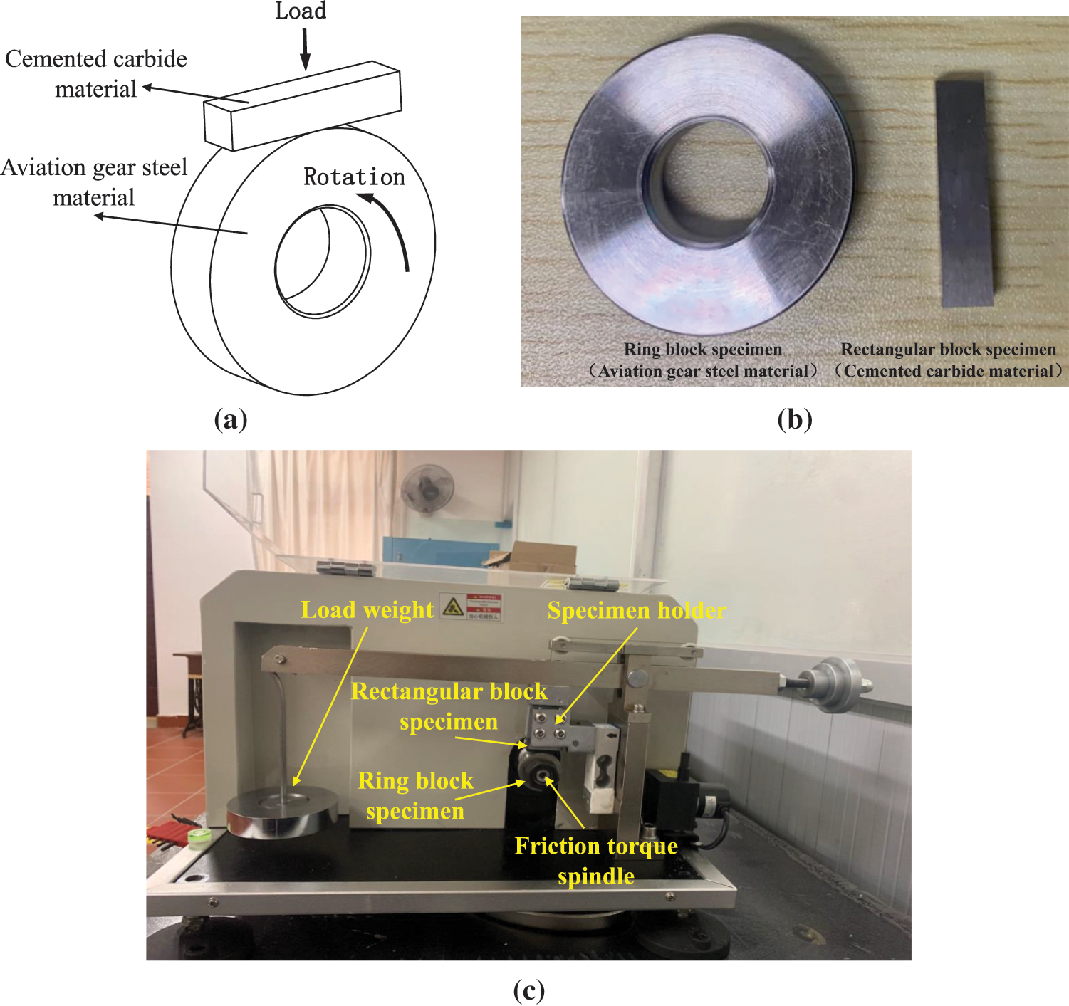
Figure 1: Ring-block friction and wear test device (a) Schematic diagram of friction pair (b) Material sample (c) Physical drawing of testing machine
The material of the ring block is high hardness gear steel 15Cr14Co12Mo5Ni2WA, and the material of the rectangular block is slotting tool material K44UF hard alloy. The whole process of the test is controlled by the industrial computer of the testing machine, and the test process is monitored by the system software in real time, and the related test parameters such as load, speed, test time and so on are recorded. The change of friction force and tool material sample wear with friction distance under different lubrication conditions was obtained. 6 C60 nanoparticle cutting fluids with different C60 particle mass concentrations were prepared as the experimental group, and HM32 cutting oil was set as the control group to compare and analyze the effect of C60 nanoparticle concentration on the friction performance of cemented carbide/high strength gear steel friction pair. The lubrication condition parameters of the experimental groups are shown in Table 1. The test load is 200 N and the speed is 200 rpm. During the test, the temperature nephogram of the friction area was obtained by the infrared thermometer, and the worn surface morphology of the rectangular test block was obtained by Dino-Lite microscope and super-depth-field 3D microscope.

3 The Theory of Recursive Analysis
In order to systematically compare and analyze the friction history between the tool pair and the workpiece pair, the friction time domain signal is transformed by using the phase space reconstruction and recurrence plot theory. The evolution law of the recurrence diagram is analyzed on this basis, and the wear evolution process and wear characteristics identification law of the tool material-High-hardness Gear Steel material pair are explored. This method can provide theoretical basis and technical preparation for practical cutting applications.
Nonlinear signals contain high dimensional information. The time series signals measured in the experiment are reconstructed into a high-dimensional space, and the system is recursively analyzed in the new space. This reconstruction process is called phase space reconstruction [27]. Firstly, the friction time domain signals collected from the friction and wear experiment of the material pair are filtered to filter out white noise and environmental interference signals, and the friction time domain signal
where
where
In order to highlight the clarity of the recurrence diagram, the points with values of 1 or 0 are represented by yellow points and blue points respectively in this paper. The two-dimensional point diagram obtained by taking
Although the observation and analysis method based on recurrence plot can directly display the evolution of friction process and running-in wear from the two-dimensional recurrence plot, it cannot quantitatively analyze the friction and wear results under different lubrication conditions. Therefore, in order to quantitatively express the friction and wear signal of the workpiece-tool material friction pair, the recurrence rate related parameters are introduced.
(1) ENT (Entropy) represents the Shannon information in the recurrence diagram, which can be used to represent the stability of the friction pair system of the work-tool material. The more complex the structure of the system is, the higher the ENT is [29,30].
(2) ADL (Average diagonal line length), which represents the average length of the diagonal structure in the recurrence plot and represents the periodicity of the system [31].
where
The variation curves of friction coefficient with friction time under lubrication conditions of different experimental groups are shown in Fig. 2. It can be seen from Fig. 2 that the friction coefficient of the dry friction experimental group is large and shows a non-linear growth trend with the increase of friction distance. Although the friction coefficient of the HM32 experimental group is much lower than that of the dry friction experimental group, the friction coefficient is still large and has an unstable fluctuation trend with the increase of friction distance. However, the average friction coefficients of the cutting fluids with 6 different concentrations of C60 particles are significantly lower than those of the HM32 control group, and the friction coefficient curves under the lubrication of C60 nanoparticles cutting fluids were more stable. The results show that the addition of C60 nanoparticles can effectively reduce the friction coefficient of K44UF cemented carbide/15Cr14Co12Mo5Ni2WA gear steel friction pair, and greatly reduce the friction force and friction fluctuation. The friction force and the fluctuation of the friction force are greatly reduced, and the average value of the friction force is reduced by more than 45%. When the concentration of C60 particles is 200 ppm, the friction coefficient is the smallest and the effect is the best. When the concentration of C60 particles is 200 ppm, the friction coefficient is the smallest, and the average friction force decreases by 56.0%.
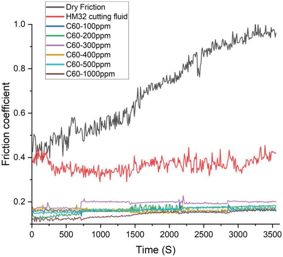
Figure 2: Friction coefficient curves under different experimental group lubrication conditions
In order to further determine the friction and wear performance, the wear width and the wear depth of the tool material test block surface under different friction distances are extracted by super-depth-field 3D microscope, and the preliminary wear evaluation are obtained. The wear width of the tool material test block under the lubrication conditions of different experimental groups is shown in Fig. 3. It can be seen from Fig. 3 that the wear width of the test block under the lubrication of HM32 cutting fluid is slightly lower than that under dry friction. However, the wear width shows a nonlinear and rapid growth trend with the increase of friction length under the lubrication of HM32 cutting fluid.
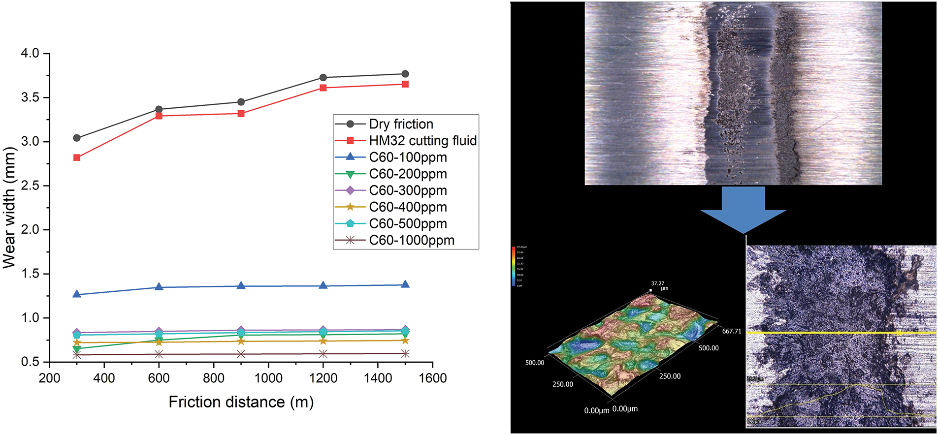
Figure 3: Wear width curves under different experimental group lubrication conditions
With the addition of C60 nanoparticles to the original cutting fluid, the wear width at different friction distances decreased significantly, and the wear width showed a nonlinear and slow growth trend. When the concentration of C60 nanoparticles reaches 200 ppm and above, the wear width is further reduced to less than 1.0 mm. The change trend of wear curve with friction distance is similar to that of friction coefficient curve under different experimental conditions. When the concentration of C60 is too low, the improvement of friction and wear properties is limited. However, when the concentration of C60 is increased to 200 ppm, the lubrication performance is significantly improved. Compared with HM32 cutting fluid, C60 nano-particle cutting fluid can greatly reduce the wear of tool material. The average value of wear width decreased by 62.36%–83.65%, and the average value of the wear depth decreased by 43.14%–71.15%.
It can be seen from the changing process of friction coefficient and wear that the friction pair composed of tool and workpiece material has nonlinear characteristics with the change of friction distance. Meanwhile, the comparative analysis shows that the addition of C60 nanoparticles cutting fluid can reduce the friction coefficient of the workpiece/tool friction pair and the wear of the tool material. It can provide a certain reference value for the improvement of the actual cutting process.
Firstly, the friction signal data of the ring-block friction and wear test is filtered and denoised, and the processed time domain signal is reconstructed in phase space and the corresponding recurrence plot is calculated. The delay time
In the process of friction and wear, 5 groups of course tests with a friction distance of 300 m and a friction time of 720 s are carried out continuously under the conditions of each experimental group. The first 600 s in each group of course tests are analyzed and the corresponding recurrence plots are constructed. The recurrence plots of five courses are generated in each experimental group. By analyzing the recurrence plot and nonlinear characteristics of friction signals under different lubrication conditions, the nonlinear characteristics of the system and the evolution process of friction process and wear can be reflected [35].
The evolutions of the recurrence plots of the friction signal under different experimental groups are shown in Figs. 4 to 11.
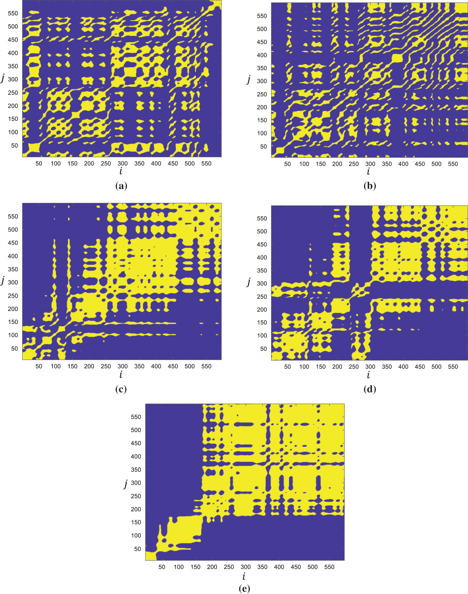
Figure 4: Recurrence plots of different courses under dry friction condition friction distance = (a) 0~300 m (b) 300~600 m (c) 600~900 m (d) 900~1200 m (e) 1200~1500 m
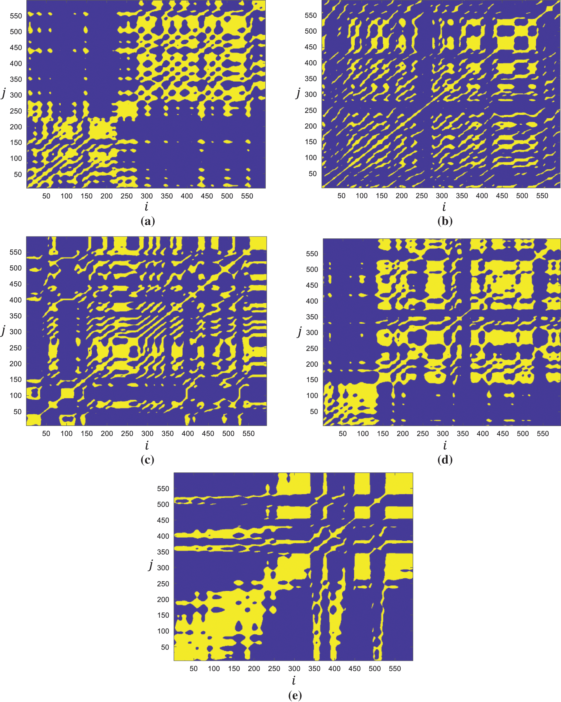
Figure 5: Recurrence plots of different courses under HM32 cutting fluid lubrication condition friction distance = (a) 0~300 m (b) 300~600 m (c) 600~900 m (d) 900~1200 m (e) 1200~1500 m
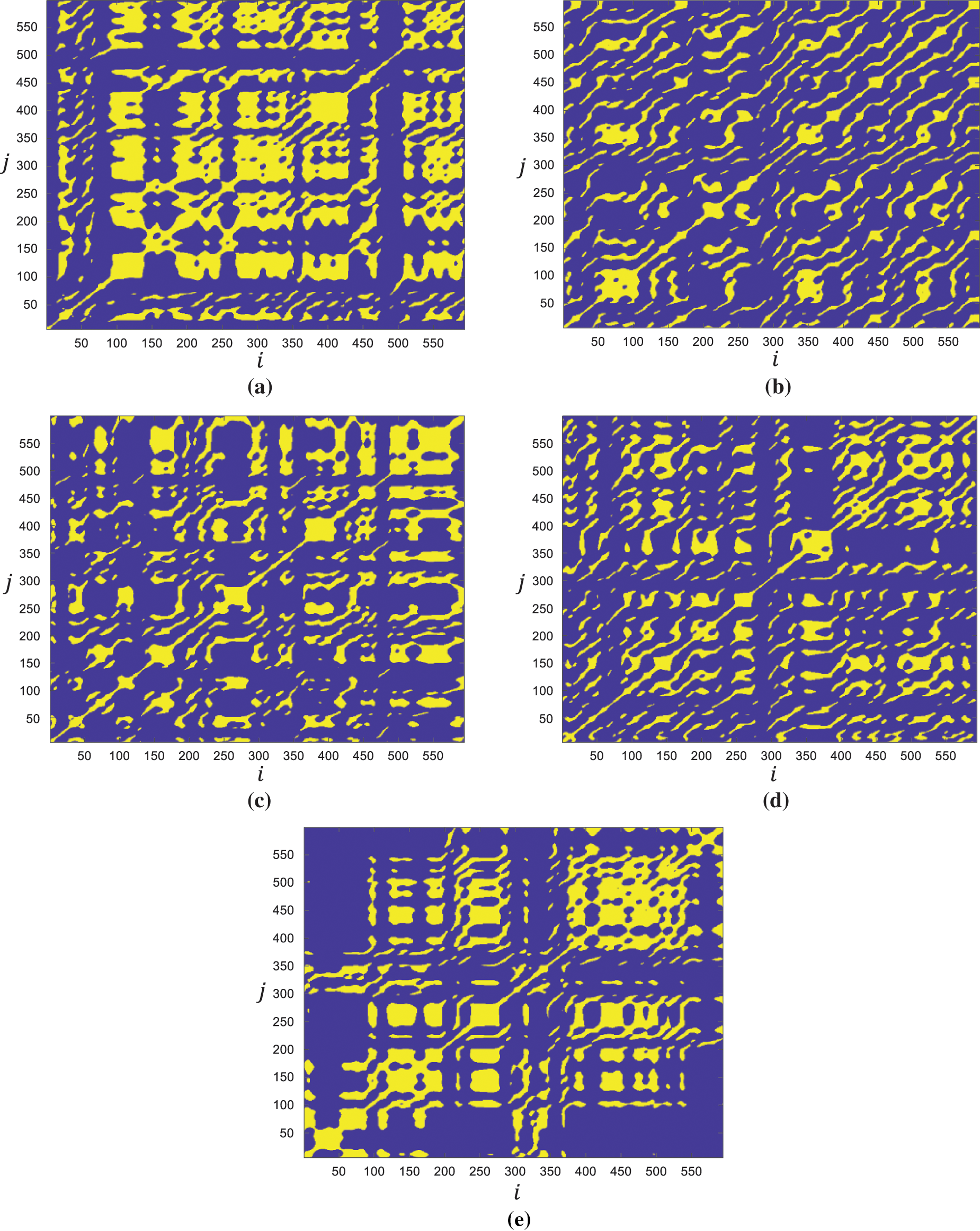
Figure 6: Recurrence plots of different courses under 100 ppm C60 nanoparticle cutting fluid lubrication friction distance = (a) 0~300 m (b) 300~600 m (c) 600~900 m (d) 900~1200 m (e) 1200~1500 m
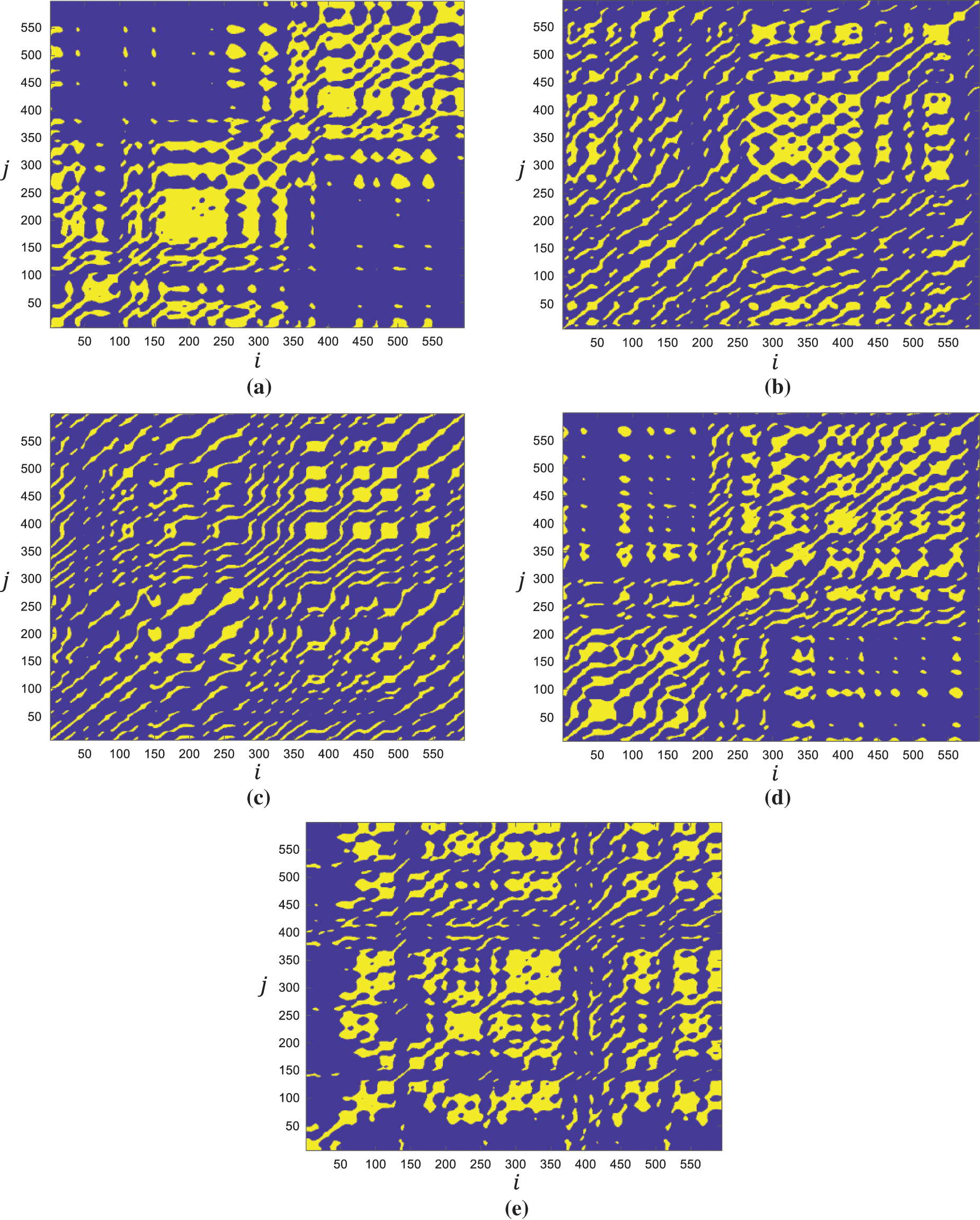
Figure 7: Recurrence plots of different courses under 200 ppm C60 nanoparticle cutting fluid lubrication friction distance = (a) 0~300 m (b) 300~600 m (c) 600~900 m (d) 900~1200 m (e) 1200~1500 m
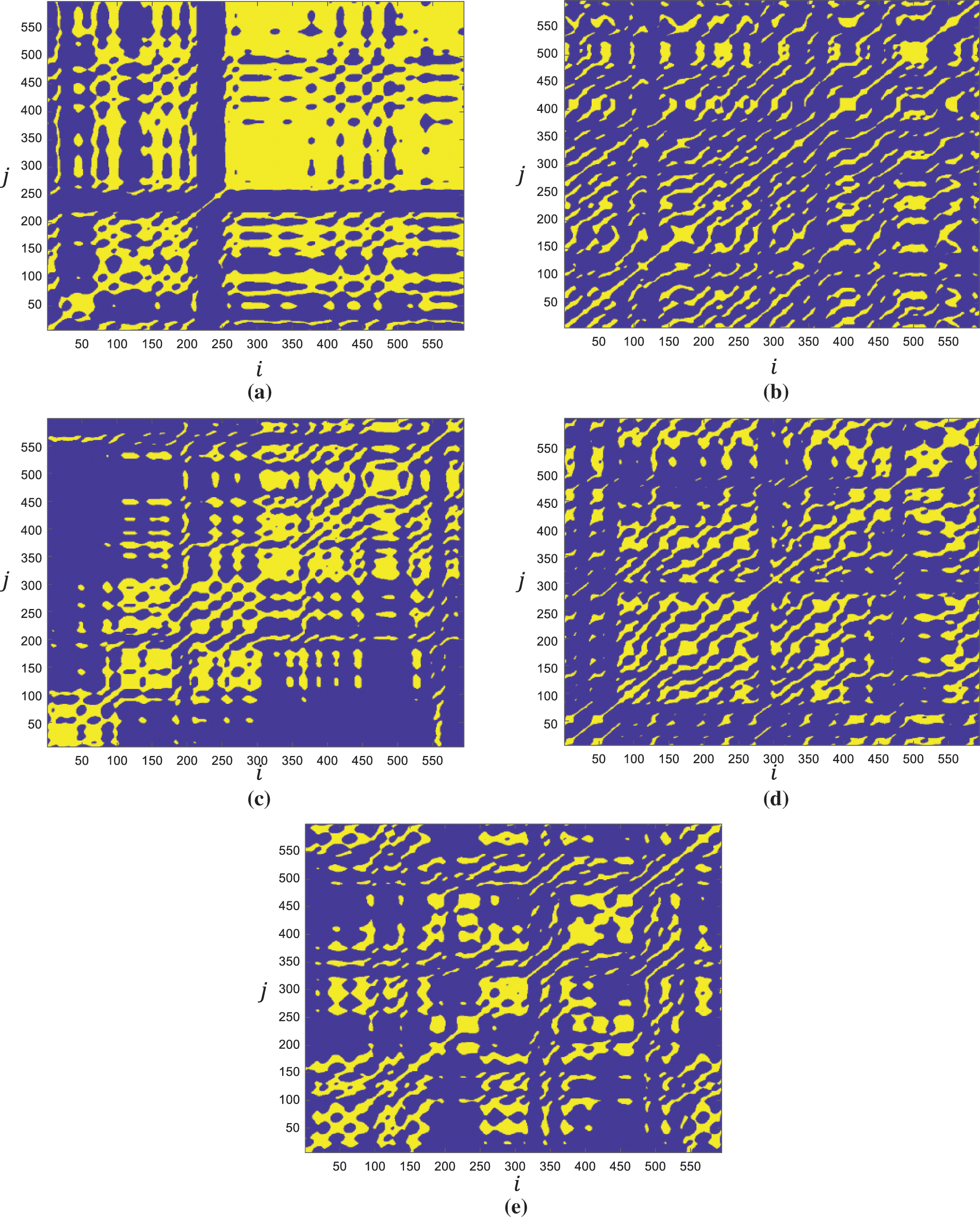
Figure 8: Recurrence plots of different courses under 300 ppm C60 nanoparticle cutting fluid lubrication friction distance = (a) 0~300 m (b) 300~600 m (c) 600~900 m (d) 900~1200 m (e) 1200~1500 m
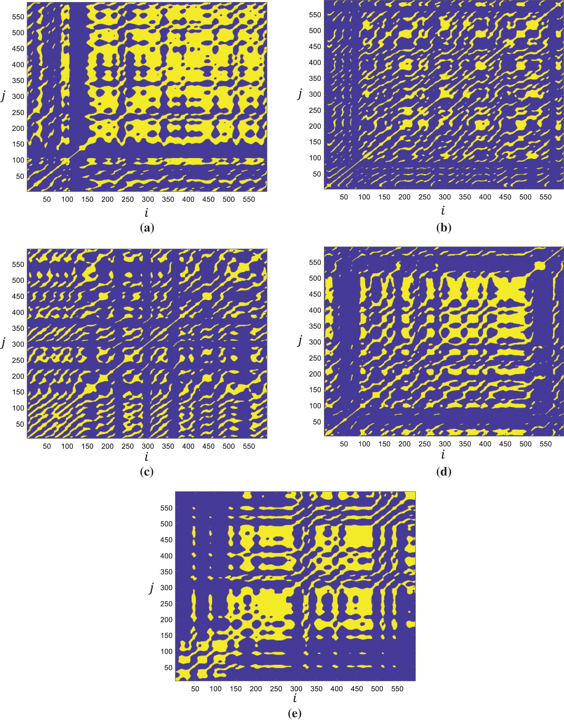
Figure 9: Recurrence plots of different courses under 400 ppm C60 nanoparticle cutting fluid lubrication friction distance = (a) 0~300 m (b) 300~600 m (c) 600~900 m (d) 900~1200 m (e) 1200~1500 m
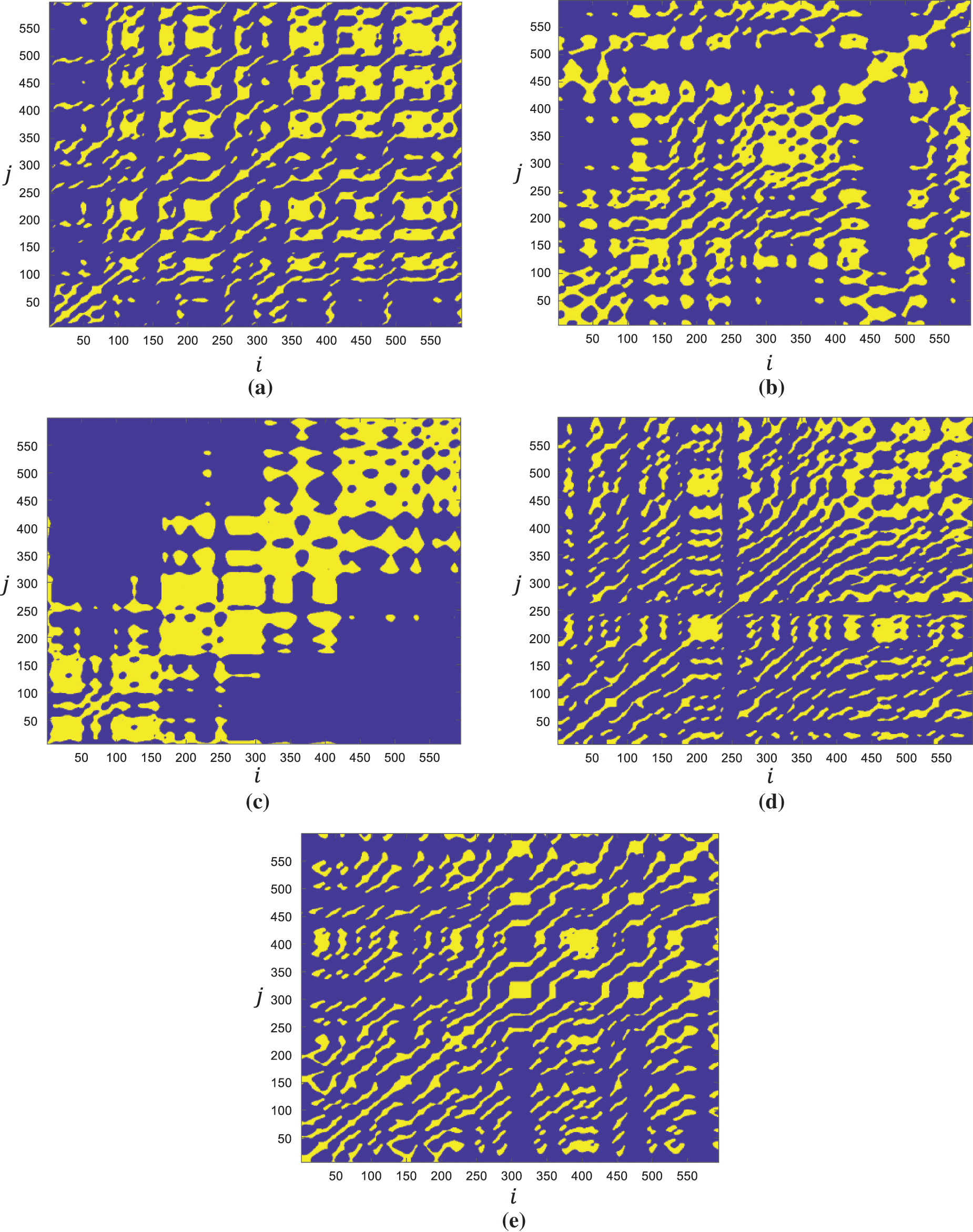
Figure 10: Recurrence plots of different courses under 500 ppm C60 nanoparticle cutting fluid lubrication friction distance = (a) 0~300 m (b) 300~600 m (c) 600~900 m (d) 900~1200 m (e) 1200~1500 m
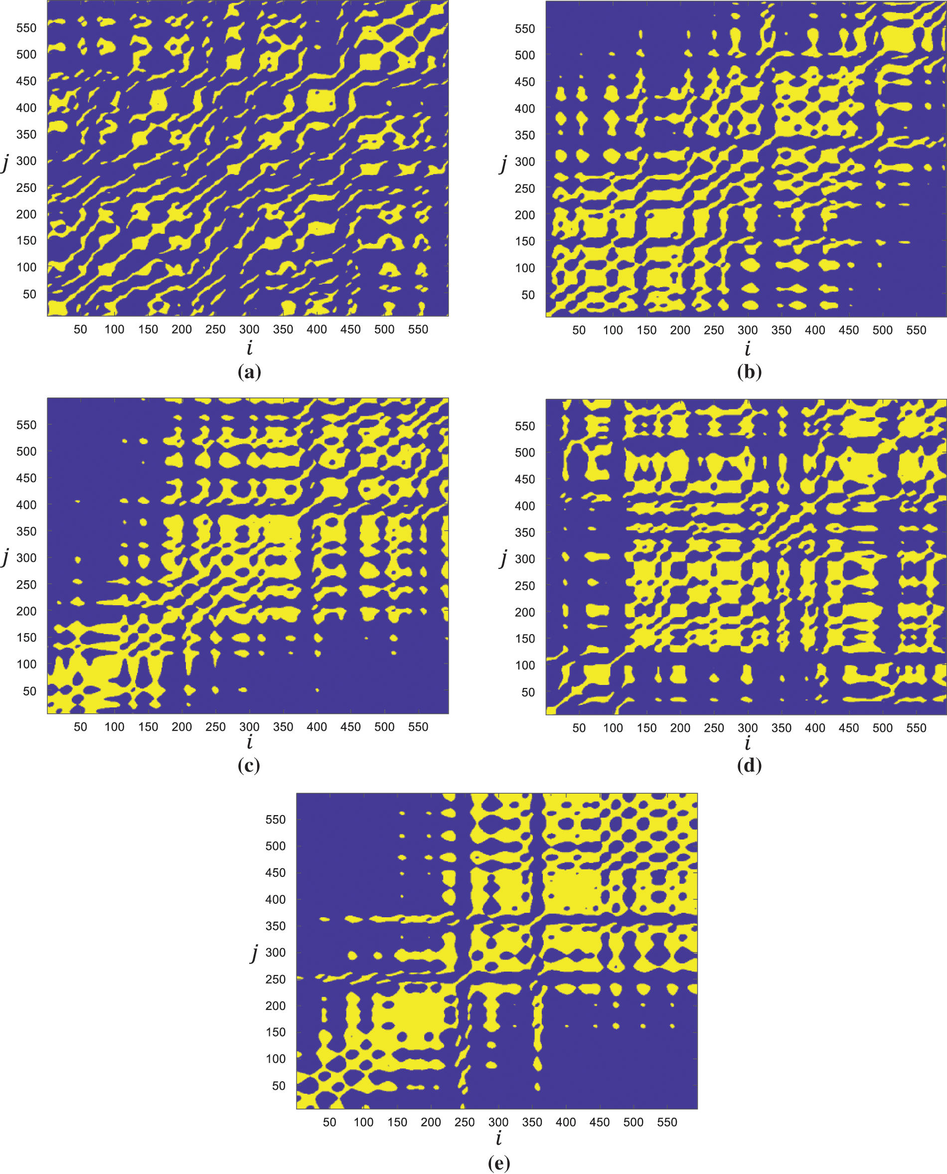
Figure 11: Recurrence plots of different courses under 1000 ppm C60 nanoparticle cutting fluid lubrication friction distance = (a) 0~300 m (b) 300~600 m (c) 600~900 m (d) 900~1200 m (e) 1200~1500 m
It can be seen from Fig. 4 that in the initial stage of 0~300 and 300~600 m friction distance in the dry friction condition, there are large yellow spots in the recurrence diagram. However, the overall distribution of yellow dots is relatively uniform, indicating that the state is relatively stable and there is no sudden change in friction and wear. As the friction distance reaches 600~900 m, larger yellow blocks appear in the recurrence plot than that in the initial stage, and the distribution of color blocks is uneven, indicating that the state of the friction and wear system is gradually unstable and sudden changes occur. When the friction distance further reaches the stage of 900~1200 and 1200~1500 m, the yellow blocks in the recurrence plot further expand. Meanwhile, the distribution of color blocks is extremely uneven, and the area of the whole rectangular yellow block even reaches half of the recurrence plot. which indicates that the friction and wear system is extremely unstable, in the stage of sudden and severe friction and wear, and the system wear is serious. It shows that the friction and wear system is extremely unstable and is in the stage of sudden severe friction and wear.
In the initial stage of the friction distance of 0~300 m under the HM32 cutting fluid lubrication condition, there are slightly large yellow spots in the recurrence plot. Although the overall distribution of yellow blocks is uneven, the overall friction and wear system is still in a stable state. When the friction distance is extended to 300~600 and 600~900 m, the yellow spots on the recurrence plot are evenly distributed and diffuse like water droplets. It indicates that the system has stepped into a stable wear stage and is in a chaotic and unpredictable stable state. However, when the friction distance is further extended to 300~600 and 600~900 m, rectangular yellow blocks appear in the recurrence plot, the area of rectangular yellow blocks gradually increases, and the overall distribution of yellow blocks is uneven. It indicates that the friction and wear system transits from the stable wear stage to the severe friction and unstable stage.
In the initial stage of the friction distance of 0~300 m under the 100 ppm C60 nano-particle cutting fluid lubrication condition, although there are rectangular yellow spots in the recurrence diagram, the overall distribution of yellow spots is relatively uniform. It shows that the system has a slight fluctuation in the initial stage, but the whole system is in a stable state. When the friction distance is extended to 300~600, 600~900 and 900~1200 m, the yellow spots in the recurrence plot are more evenly distributed, and the yellow spots are like the diffusion phenomenon of water droplets. It indicates that the system has stepped into a stable wear stage and is in a chaotic and unpredictable stable state. As the friction distance continues to extend to 1200~1500 m, rectangular yellow blocks reappear in the recurrence plot, and the area of yellow blocks becomes slightly larger, but the overall distribution is still relatively uniform. It shows that the system transits from the stage of stable wear to the stage of intensified friction, but the degree of intensified friction and wear of the system is not large, and it still maintains a relatively stable state.
In the initial stage of the friction distance of 0~300 m under the 200 ppm C60 nano-particle cutting fluid lubrication condition, the corresponding recurrence plot also shows the distribution of rectangular yellow dots, but the overall distribution of yellow dots is relatively uniform. It shows that the system fluctuates slightly in the initial stage of friction and wear, but the whole system is still in a stable state. When the friction distance is extended to 300~600 and 600~900 m, the yellow spots in the recurrence plot are more evenly distributed, and the yellow spots diffuse like water droplets melting water, which indicates that the system has entered a stable wear stage and is in a chaotic and unpredictable stable state. As the friction distance continues to extend to 900~1200 and 1200~1500 m, the yellow spots continue to diffuse and distribute evenly in the recurrence plot, and there is no phenomenon that the yellow spots become larger and unevenly distributed. It shows that the system does not transit from the stable wear stage to the severe friction stage, and continues to maintain a stable state of stable wear.
In the initial stage of the friction distance of 0~300 m under the 300 ppm C60 nano-particle cutting fluid lubrication condition, the corresponding recurrence plot also shows the distribution of rectangular yellow dots, but the overall distribution of yellow dots is relatively uniform. It shows that the system fluctuates slightly in the initial stage of friction and wear, but the whole system is still in a stable state. As the friction distance continues to extend to 300~1200 m, the distribution of yellow spots in the recurrence plot becomes more uniform, and the yellow spots diffuse like water droplets. It indicates that the system maintains a steady wear phase and is in a chaotic and unpredictable steady state. It is consistent with the lubrication condition of 200 ppm C60 nano-particle cutting fluid, it does not transit from the stable wear stage to the severe friction stage, and it continues to maintain a stable state of stable wear.
In the initial stage of the friction distance of 0~300 m under the 400 ppm C60 nano-particle cutting fluid lubrication condition, the corresponding recurrence plot shows the distribution of rectangular yellow spots, but the overall distribution of yellow spots is relatively uniform. It indicates that the system fluctuates slightly in the initial stage of friction and wear, but the overall system is still in a stable state. As the friction distance continues to extend to 300~600, 600~900, 900~1200 m, the yellow spots in the recurrence plot are more evenly distributed, and the yellow spots diffuse like water droplets. It indicates that the system maintains a steady wear phase and is in a chaotic and unpredictable steady state. However, as the friction distance continues to extend to 1200~1500 m, smaller rectangular yellow blocks appear in the recurrence plot, but the overall distribution of yellow blocks in the recurrence plot is relatively uniform. It shows that the system does not transit from the stage of stable wear to the stage of intensified friction, but the degree of intensified friction and wear of the system is not large, and it still maintains a relatively stable state.
In the initial stage of the friction distance of 0~300 m under the 500 ppm C60 nano-particle cutting fluid lubrication condition, the yellow spots in the recurrence diagram are uniformly distributed in the initial stage of friction distance from 0 to 300 m and from 300 to 600 m, and the yellow spots diffuse like water droplets melted water. It shows that the system is in a chaotic and unpredictable stable state. When the friction distance reaches 600~900 m, rectangular yellow dots appear in the recurrence plot, and the distribution of yellow dots is uneven. It shows that the system transits from the stable wear stage to the intensified friction stage, and is in an unstable state of severe friction and sudden fluctuation. However, as the friction distance continues to extend to 900~1200 and 1200~1500 m, the rectangular yellow blocks of the recurrence plot disappear, and the yellow spots redistribute evenly, such as the diffusion of water droplets. It indicates that the system is again in the transition to the stable wear stage and in the chaotic and unpredictable stable state.
In the initial stage of the friction distance of 0~1000 m under the 500 ppm C60 nano-particle cutting fluid lubrication condition, the yellow spots of the recurrence diagram are uniformly distributed, and the yellow spots diffuse like water droplets. It shows that the system is in a chaotic and unpredictable stable state. When the friction distance reaches 300~600 and 600~900 m, rectangular yellow dots appear in the recurrence plot, and the distribution of yellow dots is uneven. It shows that the system transits from the stable wear stage to the intensified friction stage, and is in an unstable state of severe friction and sudden fluctuation. Although when the friction distance is extended to 900~1200 m, the area of the rectangular yellow dot color block in the recurrence diagram becomes smaller and the distribution of the color block is gradually uniform, the system tends to be stable. However, when the friction distance continues to extend to 1200~1500 m, rectangular yellow dots appear again in the recurrence plot, and the distribution of yellow dots is uneven. The results show that the stable wear stage of the system disappears and transits to the intensified friction stage again, and the system is in an unstable state of severe friction and sudden fluctuation.
Based on the above analysis of the recurrence plots under different lubrication conditions, it can be seen that the evolution law of friction and wear can be obtained intuitively after the recurrence plot transformation from the friction time domain signal. The recurrence plots under different lubrication conditions are similar in that the textures are clustered on the main diagonal, indicating strong chaos. In the initial stage of friction and wear, the wear is unstable and fluctuates, and the recurrence plot will show mutation patterns. In the stable stage of friction and wear, the recurrence diagram will show a pattern similar to the uniform distribution of droplets. When the stable wear stage transits to the severe wear stage, the quasi-periodic pattern will appear in the intermediate transition stage, and when the severe wear occurs, it will become a sudden change pattern again.
However, the recurrence plots under different lubrication conditions also have many differences. Under the dry friction condition, the recurrence plot in the initial stage shows a fluctuating and unstable mutation pattern. With the increase of friction distance, the recurrence plot keeps the mutation pattern of uneven distribution of yellow blocks, the area of yellow blocks becomes larger, and the degree of uneven distribution becomes more serious.
Under the lubrication condition of the HM32 cutting fluid, the recurrence plot at the initial stage also shows uneven distribution of yellow patches and abrupt changes in the pattern. When the friction distance is extended to 300~600 and 600~900 m, the yellow spots in the recurrence plot are evenly distributed and diffuse like water droplets. The system is in a chaotic and unpredictable stable state. However, as the friction distance continues to extend to 900~1200 and 1200~1500 m, the recurrence plot again shows uneven distribution of yellow blocks and sudden changes in the pattern. The system changes from a stable friction and wear stage to a sudden change and unstable severe friction and wear stage.
Under the lubrication condition of 100 ppm C60 nano-particle cutting fluid, the recurrence plot at the initial stage also shows uneven distribution of yellow blocks and abrupt changes in the pattern. When the friction distance is extended to 300~1200 m, the recurrence plot keeps the uniform distribution of yellow spots for a long time, and the system is in a chaotic and unpredictable stable state. As the friction distance continues to extend to 1200~1500 m, the recurrence diagram shows the uneven distribution of yellow blocks, but the degree of friction and wear aggravation and mutation is not high.
Under the two lubrication conditions of 200 ppm C60 nano-particle cutting fluid and 300 ppm C60 nano-particle cutting fluid, the recurrence plots at the initial stage show uneven distribution of yellow blocks and slight mutation of patterns. When the friction distance continues to extend to 300~1500 m, the recurrence plots keep the uniform distribution of yellow spots for a long time, and the system is in a chaotic and unpredictable stable state. Compared with the later stage under the 100 ppm C60 nano-particle cutting fluid lubrication condition, there is no sudden change pattern.
As the concentration of C60 nanoparticles cutting fluid increases to 400, 500 and 1000 ppm, the recurrence plots at the initial stage also show uneven distribution of yellow blocks and slight mutation of patterns. When the friction distance continues to extend, the recurrence plots remain in a chaotic and unpredictable stable state for a period of time. However, in the later stage when the friction distance continues to extend, the uneven distribution of yellow blocks and the sudden change of patterns appear repeatedly in the recurrence plots. It indicates that the instability of the friction and wear system is intensified.
4.4 Quantitative Recursive Analysis
From the two-dimensional recurrence plots, the evolution of friction and wear under different lubrication conditions was analyzed. In order to further quantitatively analyze the friction and wear of the tool material-workpiece material friction pair under different lubrication conditions, the ENT and ADl indexes in the above recurrence plots are extracted for comparative analysis.
The ENT and ADL plots for different lubrication conditions are shown in Figs. 12 and 13, respectively. By comparing the two figures, it can be seen that with the extension of the friction distance, the curve trends of ENT and ADL are similar. The larger the ENT value is, the worse the stability of the system is, and the system is in a state of mutation and complexity. This also means that the larger the cycle length shown in the 2D recurrence plot, the larger the ADL value. It indicates that the larger the ENT and ADL values, the worse the stability of the system.
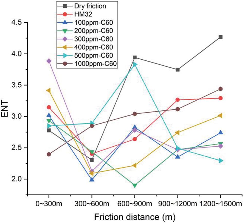
Figure 12: ENT at different friction distances under different lubrication conditions
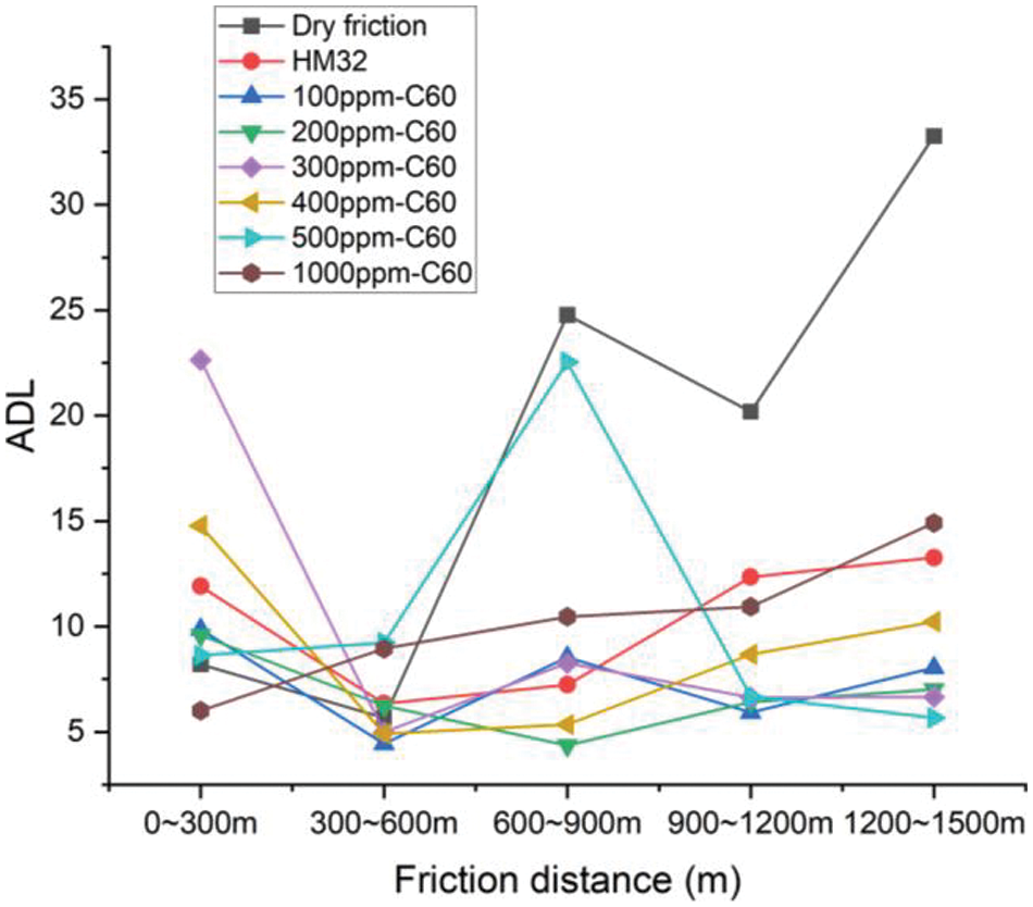
Figure 13: ADL at different friction distances under different lubrication conditions
By comparing the variation trends of ENT and ADL under different lubrication conditions, it can be seen that the values of ENT and ADL under dry friction condition are the highest, and the growth trend and fluctuation degree are the most significant, which indicates that the friction and wear of the system are intense and extremely unstable. The ENT and ADL values under the lubrication condition of HM32 original cutting fluid are lower than those under the dry friction condition, but the ENT and ADL values continue to grow with the increase of friction distance in the later period. It indicates that the system still has an increasing trend of instability. The ENT and ADL values of 100 ppm C60 nano-particle cutting fluid under the lubrication condition are lower than those of HM32 cutting fluid under the lubrication condition, and the ENT and ADL values have no continuous growth trend for a long time with the increase of friction distance in the later stage, and have a slight growth trend until the final stage.
Under the lubrication conditions of 200 ppm C60 nano-particle cutting fluid and 300 ppm C60 nano-particle cutting fluid, the ENT and ADL values are further reduced compared with those under the lubrication conditions of 100 ppm C60 nano particle cutting fluid, and the ENT and ADL values are stable for a long time and do not show an increasing trend with the increase of friction distance in the later period. The results show that the stability of the friction and wear system is the best and the lubrication effect is the best. With the increase of the nano-particle cutting fluid concentration to 400, 500 and 1000 ppm, the ENT and ADL values are low in the early stage when the friction distance is short, but the ENT and ADL values fluctuate again and continue to grow with the increase of the friction distance in the later stage. It shows that the high concentration of C60 nanoparticles will also cause the decrease of the stability of the friction and wear system and the decline of the lubricating effect. The conclusion of the overall comparative analysis is consistent with the conclusion of the observation analysis based on the two-dimensional recurrence plot in the previous section.
Based on the above analysis results, it can be seen that the friction and wear stability under the liquid lubrication is higher than that under the dry friction condition. Meanwhile, the friction and wear stability of C60 nano-particle cutting fluid is higher than that of HM32 cutting fluid. Based on the comparative analysis of different concentrations of C60 nano-particle cutting fluid lubrication conditions, it can be seen that when the concentration of C60 is too low, the improvement of system stability and lubrication performance is low. When the concentration of C60 reaches 200~300 ppm, the stability and lubrication performance of the friction and wear system reach the best. When the concentration of C60 increases to 400 ppm or above, the stability and lubrication performance of the system decrease. Therefore, it can be concluded that the stability and anti-friction and wear resistance of the workpiece-tool material friction pair system can be optimized under the lubrication of 200~300 ppm C60 nano-particle cutting fluid.
In order to verify the conclusions of the friction and wear experiments and the recursive analysis, the milling experiments were carried out. The physical drawing of the milling experimental platform and related test instruments is shown in Fig. 14. The milling machine is FEELER VMP-40A vertical machining center. The experimental process parameters are shown in Table 1. Dry cutting group, HM32 cutting fluid lubrication group and C60 nanoparticle cutting fluid lubrication group (C60 concentration is 200 ppm) are set up in the experiment. 15 steps are performed in each experimental group. The milling force and tool wear after the cutting step are detected during the machining process.
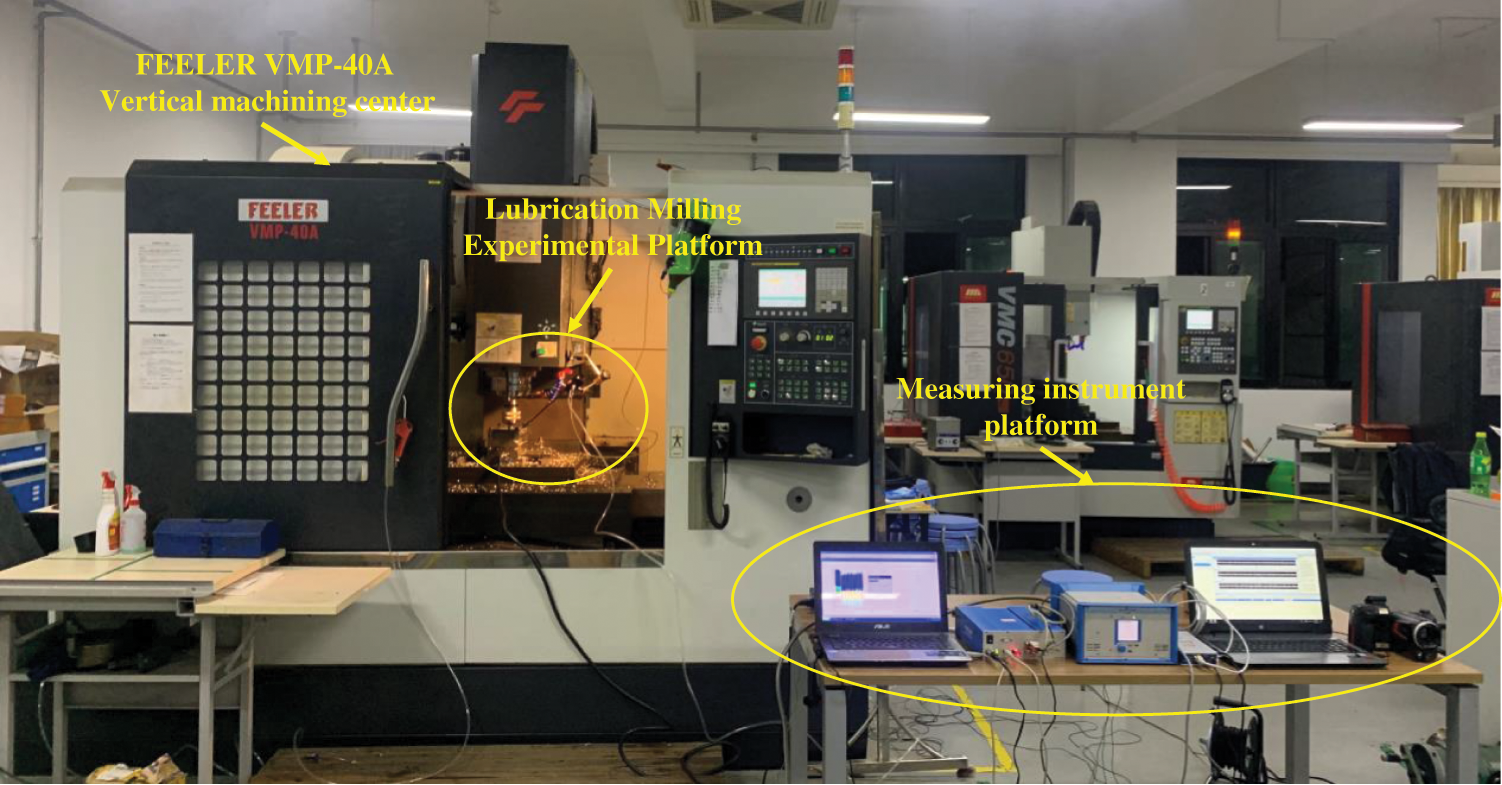
Figure 14: Milling experimental processing platform
The milling force under different lubrication conditions is shown in Fig. 15. Compared with the dry cutting test group, the milling force peak value under the HM32 cutting fluid lubrication decreased by 48.43%, and the milling force mean value decreased by 36.59%; However, the milling force peak value decreases by 56.66% and the milling force mean value decreases by 43.88% under the lubrication of C60 nanoparticle cutting fluid; Meanwhile, the milling force curve lubricated by the HM32 cutting fluid has an unstable fluctuation and a slow growth trend; However, the cutting force under the C60 nano-particle cutting fluid lubrication is relatively stable and has no increasing trend.
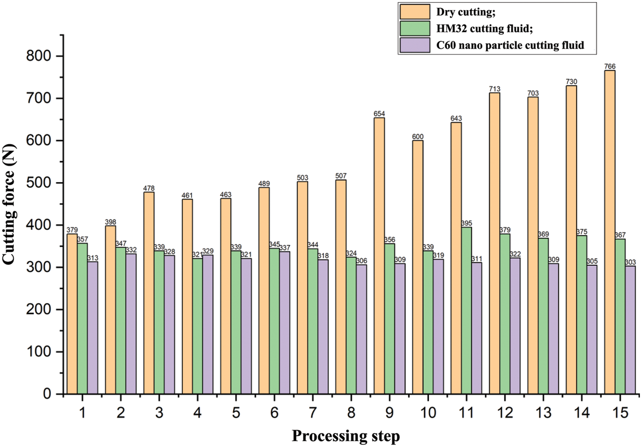
Figure 15: Milling force under different experimental lubrication condition groups
The flank wear width of four inserts in the milling tool is measured and counted under different experimental conditions and different working steps. The flank wear width under different lubrication conditions is shown in Fig. 16. Compared with the dry cutting condition, the wear width under the HM32 cutting fluid lubrication and the C60 nanoparticle cutting fluid lubrication is significantly reduced. After the fifth process step, the wear width of the inserts under the HM32 cutting fluid lubrication is reduced by 41.27% on average, and the wear width of the inserts under C60 nanoparticle cutting fluid lubrication is reduced by 50.79% on average; After the tenth process step, the wear width of the inserts under the HM32 cutting fluid lubrication is reduced by 45.57%, and the wear width of the inserts under C60 nanoparticle cutting fluid lubrication is reduced by 58.23% on average; After the 15th process step, the wear width of the insert under the HM32 cutting fluid lubrication is reduced by 32.98%, and the average reduction of wear width is 62.77% under the 60 nanoparticle cutting fluid lubrication. Compared with the HM32 cutting fluid, the wear width under C60 nano-particle cutting fluid lubrication is significantly reduced.
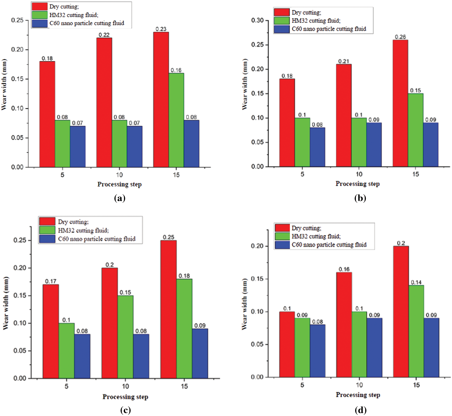
Figure 16: The flank wear width of four inserts in milling cutter under different lubrication conditions (a) Insert 1 (b) Insert 2 (c) Insert 3 (d) Insert 4
Meanwhile, the tool wear width under the HM32 cutting fluid lubrication condition has an obvious upward trend with the increase of working steps. However, the wear width does not increase under the C60 nanoparticle cutting fluid lubrication condition, and the wear width is maintained below 0.09 mm. It indicates that C60 nanoparticles cutting fluid plays a significant role in antifriction and lubrication in the cutting process. It increases the wear resistance and the cutting tool life, and promotes the stability of the cutting process and the accuracy retention of the workpiece. Based on the comparison and analysis of the cutting test results under different lubrication conditions, the results show that compared with the dry cutting condition and the original cutting fluid lubrication condition, the cutting force and tool wear under the C60 nanoparticle cutting fluid lubrication are significantly reduced. The wear resistance and tool life of cutting tools are increased, and the stability of the cutting process and the accuracy retention of workpieces are improved. It verifies the analysis conclusion of the friction and wear characteristics of the tool-workpiece material friction pair based on the recursion theory in the above section, and provides a technical basis for the cutting application of high hardness alloy steel.
In order to systematically compare and analyze the friction history between the tool pair and the workpiece pair, the friction time domain signal is transformed by using phase space reconstruction and recurrence plot theory. On this basis, the evolution law of the recurrence plot was analyzed, and the wear evolution process and wear feature identification law of the tool material-high hardness alloy steel pair were explored. The proposed method in this paper can provide a theoretical basis and technical preparation for practical cutting applications.
(1) The wear signals under dry friction conditions, HM32 cutting fluid lubrication and C60 nano-particle cutting fluid lubrication with different concentrations are recursively analyzed, and the one-dimensional wear signals which are difficult to analyze are transformed into high-dimensional features which are easy to analyze. It can more intuitively and accurately reflect the friction and wear situation of the friction pair of the high hardness alloy steel-hard alloy tool material.
(2) The friction and wear of the friction pair lubricated by C60 nano-particle cutting fluid are more stable than that lubricated by HM32 cutting fluid at different friction distances, and the fluctuation is smaller.
(3) When the concentration of C60 nanoparticles is too low or too high, the friction and wear of friction pairs still have the trend of aggravation and fluctuation. When the concentration of C60 nanoparticles is 200~300 ppm, the stability of the friction pair system is best. It can provide a theoretical basis and technical preparation for the practical cutting application of high hardness alloy steel.
(4) The cutting experiments under different lubrication conditions are carried out. The results show that C60 nanoparticles cutting fluid can significantly improve and reduce the cutting force and tool wear, and increase the wear resistance of cutting tools and tool life. It verifies the accuracy of the proposed method for the friction and wear characteristics of the tool-workpiece material friction pair based on the recursive theory, and provides a technical basis for the actual cutting application of high hardness alloy steel.
Acknowledgement: The work is financially supported by National Natural Science Foundation of China, National Key Research and Development Project, Natural Science Foundation of Guangdong Province, China, Natural Science Foundation of Fujian Province, China, the Aero-nautical Science Foundation of China, and the Fundamental Research Funds for the Central Universities.
Funding Statement: The work is financially supported by National Natural Science Foundation of China (No. 51605403), National Key Research and Development Project (2020YFB1713503), Natural Science Foundation of Guangdong Province, China (No. 2015A030310010), Natural Science Foundation of Fujian Province, China (No. 2016J01012), the Aero-nautical Science Foundation of China (No. 20183368004), and the Fundamental Research Funds for the Central Universities under Grant (No. 20720190009).
Author Contributions: The authors confirm contribution to the paper as follows: study conception and design: Jingshan Huang, Bin Yao; data collection: Jingshan Huang, Qixin Lan, Zhirong Pan; analysis and interpretation of results: Jingshan Huang, Bin Yao; draft manuscript preparation: Jingshan Huang, Zhirong Pan. All authors reviewed the results and approved the final version of the manuscript.
Availability of Data and Materials: The raw/processed data required to reproduce the above findings cannot be shared at this time as the data also forms part of an ongoing study.
Conflicts of Interest: The authors declare that the research was conducted in the absence of any commercial or financial relationships that could be construed as a potential conflict of interest.
References
1. Wang, X., Zhao, J., Gan, Y. (2022). Cutting performance and wear mechanisms of the graphene-reinforced Al2O3-WC-TiC composite ceramic tool in turning hardened 40Cr steel. Ceramics International, 48(10), 13695–13705. [Google Scholar]
2. Karlsson, P., Gaard, A., Krakhmalev, P. (2012). Galling resistance and wear mechanisms for cold-work tool steels in lubricated sliding against high strength stainless steel sheets. Wear, 286, 92–97. [Google Scholar]
3. Li, Y., Zheng, G., Zhang, X. (2019). Cutting force, tool wear and surface roughness in high-speed milling of high-strength steel with coated tools. Journal of Mechanical Science and Technology, 33, 5393–5398. [Google Scholar]
4. Yin, Q., Li, C., Dong, L. (2018). Effects of the physicochemical properties of different nanoparticles on lubrication performance and experimental evaluation in the NMQL milling of Ti-6Al–4V. The International Journal of Advanced Manufacturing Technology, 99, 3091–3109. [Google Scholar]
5. Sharma, A. K., Singh, R. K., Dixit, A. R. (2017). Novel uses of alumina-MoS2 hybrid nanoparticle enriched cutting fluid in hard turning of AISI 304 steel. Journal of Manufacturing Processes, 30(12), 467–482. [Google Scholar]
6. Sharma, K., Tiwari, A. K., Dixit, A. R. (2018). Novel uses of alumina/graphene hybrid nanoparticle additives for improved tribological properties of lubricant in turning operation. Tribology International, 119, 99–111. [Google Scholar]
7. Huang, J. S., Sun, H., Yao, B. (2021). Study on dispersion stability and friction characteristics of C60 nano-microsphere lu-bricating additives for improving cutting conditions in manufacturing process. Mathematical Problems in Engineering, 10, 2724743–2724753. [Google Scholar]
8. Lian, Y. S., Chen, H. F., Mu, C. L. (2019). Performance of microtextured tools fabricated by inductively coupled plasma etching in dry cutting tests on medium carbon steel workpieces. International Journal of Precision Engineering and Manufacturing-Green Technology, 6(2), 175–188. [Google Scholar]
9. Gowthaman, P. S., Jeyakumar, S., Saravanan, B. A. (2020). Machinability and tool wear mechanism of Duplex stainless steel—A review. Materials Today: Proceedings, 26, 1423–1429. [Google Scholar]
10. Jamil, M., He, N., Gupta, M. K. (2022). Tool wear mechanisms and its influence on machining tribology of face milled titanium alloy under sustainable hybrid lubri-cooling. Tribology International, 170, 107497. [Google Scholar]
11. Seved, H. M., Behnam, D., Seyed, A. N. (2019). Effects of reinforced nanofluid with nanoparticles on cutting tool wear morphology. Journal of Central South University, 26(5), 1050–1064. [Google Scholar]
12. Mohanraj, T., Shankar, S., Rajasekar, R. (2020). Tool condition monitoring techniques in milling process—A review. Journal of Materials Research and Technology, 9(1), 1032–1042. [Google Scholar]
13. Cao, X. C., Chen, B. Q., Yao, B. (2019). Combining translation-invariant wavelet frames and convolutional neural network for intelligent tool wear state identification. Computers in Industry, 106, 71–84. [Google Scholar]
14. Kuntoğlu, M., Sağlam, H. (2021). Investigation of signal behaviors for sensor fusion with tool condition monitoring system in turning. Measurement, 173, 108582. [Google Scholar]
15. Zhu, H., Lu, B. B., Li, J. Q. (2010). Nonlineartheory and methods of researching tribological problems. Journal of Mechanical Engineering, 46(15), 82–88. [Google Scholar]
16. Ding, C., Zhu, H., Sun, G. (2018). Chaotic characteristics and attractor evolution of friction noise during friction process. Friction, 6, 47–61. [Google Scholar]
17. Oleksowicz, S., Polak, A. (2011). Modeling of the friction process in a frictional pair using chaos theory tools. Tribology Letters, 41, 495–501. [Google Scholar]
18. Zhou, Y., Zhu, H., Zuo, X. (2014). Chaotic characteristics of measured temperatures during sliding friction. Wear, 317(1–2), 17–25. [Google Scholar]
19. Zhou, Y., Zhu, H., Zuo, X. (2015). The nonlinear nature of friction coefficient in lubricated sliding friction. Tribology International, 88, 8–16. [Google Scholar]
20. Lang, S., Zhu, H., Wei, C. L. (2023). Study on the boundedness, stability and dynamic characteristics of friction system based on fractal and chaotic theory. Tribology International, 180, 108228. [Google Scholar]
21. Xing, P. F., Li, G. B., Gao, H. T. (2022). Experimental study on friction state identification of sliding bearing based on friction vibration recurrence characteristics. Vibration and Shock, 41(15), 1–8. [Google Scholar]
22. Zaldivar, I. M., Strozzi, F., Dueri, S. (2008). Characterization of regime shifts in environmental time serieswith recurrence quantification analysis. Ecological Modelling, 210(1–2), 58–70. [Google Scholar]
23. Zamen, S., Dehghan-Niri, E., Ilami, M. (2022). Recurrence analysis of friction based dry-couplantultrasonic Lamb waves in plate-like structures. Ultrasonics, 120, 106635. [Google Scholar] [PubMed]
24. Ziaei-Halimejani, H., Nazemzadeh, N., Zarghami, R. (2021). Fault diagnosis of chemical processes based on joint recurrence quantification analysis. Computers & Chemical Engineering, 155, 107549. [Google Scholar]
25. Xiao, H., Li, Y. R., Lv, Y. (2011). Gear fault recognition based on recursive quantitative analysis and gaussian mixture model. Journal of Vibration Engineering, 24(1), 84–88. [Google Scholar]
26. Fan, W., He, Y. Z., Wang, Y. (2021). Fault diagnosis of exciting force imbalance of linear vibrating screen based on VMD-ROa. Vibration and Shock, 40(18), 25–32. [Google Scholar]
27. Zhao, H., Gao, Z. Y., Gao, J. M. (2016). A multi-source data fusion method based on phase space reconstruction. Journal of Xi’an Jiaotong University, 50(8), 84–89. [Google Scholar]
28. Zhou, B. C., Li, X. Q., Zhai, Y. H. (2001). Application of takens theory and wavelet analysis in nonlinear prediction. Journal of Jilin University (Science), 3, 21–28. [Google Scholar]
29. Sun, G., Zhu, H., Ding, C. (2017). Multifractal detrend-ed fluctuation analysis on friction coefficient during the friction process. Journal of Tribology, 140(1), 011601. [Google Scholar]
30. Huang, N. E., Shen, Z., Long, S. R. (1998). The empirical mode decomposition and Hilbert spectrum for non-linear and non-stationary time series analysis. Proceedings of the Royal Society of London A, 454, 903–995. [Google Scholar]
31. Arcentales, A., Giraldo, B. F., Caminal, P. (2011). Recurrence quantification analysis of heart rate variability and respiratory flow series in patients on weaning trials. Annual International Conference of the IEEE Engineering in Medicine and Biology Society (EMBC), 4, 2724–2727. [Google Scholar]
32. Wang, M. Q., Guo, H., Zhang, Y. A. (2019). Study on recurrence plot characteristics of friction and wear signals of porous titanium. Journal of Jiangsu University of Science and Technology: Natural Science Edition, 33(5), 46–51. [Google Scholar]
33. Lin, J. Y., Wang, Y. K., Huang, Z. P. (1999). Selection of time delay in phase space reconstruction of speech signal: Complex autocorrelation method. Signal Processing, 15(3), 220–225. [Google Scholar]
34. Arya, S. (1998). An optimal algorithm for approximate nearestneighbor searching fixed dimensions. Journal of the ACM, 45(6), 891–923. [Google Scholar]
35. Liu, Z. Q. (2018). Optimization design of broach for turbine disk mortise and study on its broaching performance. China: Harbin Institute of Technology. [Google Scholar]
Cite This Article
 Copyright © 2024 The Author(s). Published by Tech Science Press.
This work is licensed under a Creative Commons Attribution 4.0 International License , which permits unrestricted use, distribution, and reproduction in any medium, provided the original work is properly cited.


 Submit a Paper
 Propose a Special lssue
 View Full Text
 Download PDF
 Downloads
 Citation Tools