
 Submit a Paper
 Propose a Special lssue
 Open Access
ARTICLE
Strain-Rate Dependency of a Unidirectional Filament Wound Composite under Compression
1
Skolkovo Institute of Science and Technologies, Center for Materials Technologies, Moscow, Russia
2
National Research Lobachevsky State University of Nizhny Novgorod, Nizhny Novgorod, Russia
3
Dipartimento di Ingegneria Civile, Ambientale e Architettura (DICAAR), Università degli Studi di Cagliari, Cagliari (CA), Italy
4
Mechanical Engineering Department, Faculty of Engineering, Shahid Chamran University of Ahvaz, Ahvaz, Iran
5
Drilling Center of Excellence and Research Center, Shahid Chamran University of Ahvaz, Ahvaz, Iran
* Corresponding Authors: Hamid M. Sedighi. Email: ;
Computer Modeling in Engineering & Sciences 2023, 137(3), 2149-2161. https://doi.org/10.32604/cmes.2023.028179
Received 02 December 2022; Accepted 22 March 2023; Issue published 03 August 2023
 View Full Text
 Download PDF
Abstract
This article presents the results of experimental studies concerning the dynamic deformation and failure of a unidirectional carbon fiber reinforced plastic (T700/LY113) under compression. The test samples were manufactured through the filament winding of flat plates. To establish the strain rate dependencies of the strength and elastic modulus of the material, dynamic tests were carried out using a drop tower, the Split Hopkinson Pressure Bar method, and standard static tests. The samples were loaded both along and perpendicular to the direction of the reinforcing fiber. The applicability of the obtained samples for static and dynamic tests was confirmed through finite element modeling and the high-speed imaging of the deformation and failure of samples during testing. As a result of the conducted experimental studies, static and dynamic stress-strain curves, time dependencies of deformation and the stress and strain rates of the samples during compression were obtained. Based on these results, the strain rate dependencies of the strength and elasticity modulus in the strain rate range of 0.001–600 1/s are constructed. It is shown that the strain rate significantly affects the strength and deformation characteristics of the unidirectional carbon fiber composites under compression. An increase in the strain rate by 5 orders of magnitude increased the strength and elastic modulus along the fiber direction by 42% and 50%, respectively. Perpendicular loading resulted in a strength and elastic modulus increase by 58% and 50%, respectively. The average strength along the fibers at the largest studied strain rate was about 1000 MPa. The obtained results can be used to design structural elements made of polymer composite materials operating under dynamic shock loads, as well as to build models of mechanical behavior and failure criteria of such materials, taking into account the strain rate effects.Keywords
Nomenclature
| CFRP | Carbon fiber-reinforced composites |
| DIC | Digital image correlation |
| FRP | Fiber-reinforced composites |
| SHPB | Split Hopkinson Pressure Bar |
| UD | Unidirectional |
Despite recent advances, there is still ongoing research on the high-strain rate behavior of fiber-reinforced plastics, where the testing of unidirectional FRPs is the most challenging. As a rule, testing employed during research utilizes the Split Hopkinson Bar setup for strain rates of 102 to104 s−1, where uniform deformation of the sample is assumed, the theory for which has been comprehensively explained by George et al. [1]. This assumption is justified for the compressive loading of cubic or cylindrical FRP specimens, like in the works of Jia et al. [2] or Tang et al. [3]. Such specimens are prone to damage initiation at loading surfaces, resulting in the material strength being underestimated. One way of dealing with this is to implement this inevitable damage on the surface into experimental models, the approach being very difficult from practical and theoretical points of view. Such experiments require FE-analysis and a detailed comparison of FE and experimental outcomes, which is difficult in practice. In turn, from a theoretical point of view, the range of mechanisms and parameters involved is overwhelming. Factors that need to be taken into account include, but are not limited to, preliminary failure at the fiber-matrix interface of discontinuous fibers at specimen edges (both with and without loading), the influence of surface roughness, subsequent mixed-mode crack propagation and the influence of layup. Last, but not least, none of the aforementioned mechanisms is expected to be strain-rate independent, which adds a variety of unknown variables. Further reading on this vast scope of topics can be found in [4–6].
In order to overcome the problem of damage on the contact surfaces, Ploeckl et al. [7] used thin and long specimens glued in a slotted accessory with a 10 mm long gauge section for combined compressive loading, allowing for the decrease of stress concentration and implementation of the standard configuration described in ASTM D6641 [8] for the SHPB test. Apart from achieving a valid failure mode, providing a wide strain-rate range is the second principal task. For example, Li et al. [9] have achieved strain rates up to 1800 s−1 for short rectangular specimens, while only 120 s−1 was achieved for the long specimens by Ploeckl et al. Woven glass and carbon fiber composites with a balanced layup in a thermoplastic matrix were subjected to dynamic compression by Ramirez et al. [10]. It was found that carbon fiber composites showed a weak strain rate dependence, whereas glass fiber composites demonstrated a 38% increase for compressive strength for strain rates between 10−3 to 103 s−1. Glass fiber unidirectional (UD) thermoplastic composites were tested as rectangular bricks up to 800 s−1 by Kim et al. [11]. They observed a 40% increase of compressive strength and a 60% decrease of failure strain when loaded along the fibers and a 65% increase and 60% decrease, correspondingly, in perpendicular loading. Carbon/carbon woven 3D needle-punched composites studied by Li et al. [9] also showed a noticeable strain rate dependence of compressive properties. They showed that longitudinal modulus increased by 112% and failure stress by 26% with strain rates increasing from 700 to 1800 s−1. Zhu et al. [12] analyzed ultra-high-molecular-weight polyethylene cross-ply laminates with a polyurethane matrix at strain rates of 4 * 10−3 to 2.3 * 103 s−1. They observed a 177% increase for in-plane compressive strength and a 60% decrease of failure strain. The attempt of the present study is to propose SHPB outlines that provide both a valid compressive failure mode and a wide range of strain rate for UD specimens.
CFRP plates, with the dimensions of 300 mm × 290 mm × 4 mm, were fabricated according to the standard ISO 1268-5:2001 [13]. The carbon fiber used was Toray 700 and the matrix was Huntsman Renlam LY113 epoxy resin. The obtained average values for density, fiber volume fraction and porosity were 1.45 g/cm3, 60% and 1% accordingly. The test specimens were cut from the plates using a Shtalmark CNC-machine. A ⌀2.5 mm diamond-coated corn milling cutter was selected as the milling bit. The plates were fixed on a chipboard plate with a glue gun and screws. The machine cut the contours of the specimens with breaks that served as tabs that hold the specimens throughout the process. The specimens were removed by manually cutting the tabs with a Dremel™ cutter.
The dimensions of the specimens for the static tension, compression and shear tests corresponded accordingly to the requirements of ASTM D3039, D6641 and D7078/D7078M. The static tests were carried out on an Instron 5969 machine. Strain measurements were taken using the digital image correlation system Vic-3D (Correlated Solution, Inc., Irmo, South Carolina). The obtained material properties are given in Table 1 for loading both along (L) and perpendicular (T) to the fiber direction. The experimental setup is shown on Fig. 1a.
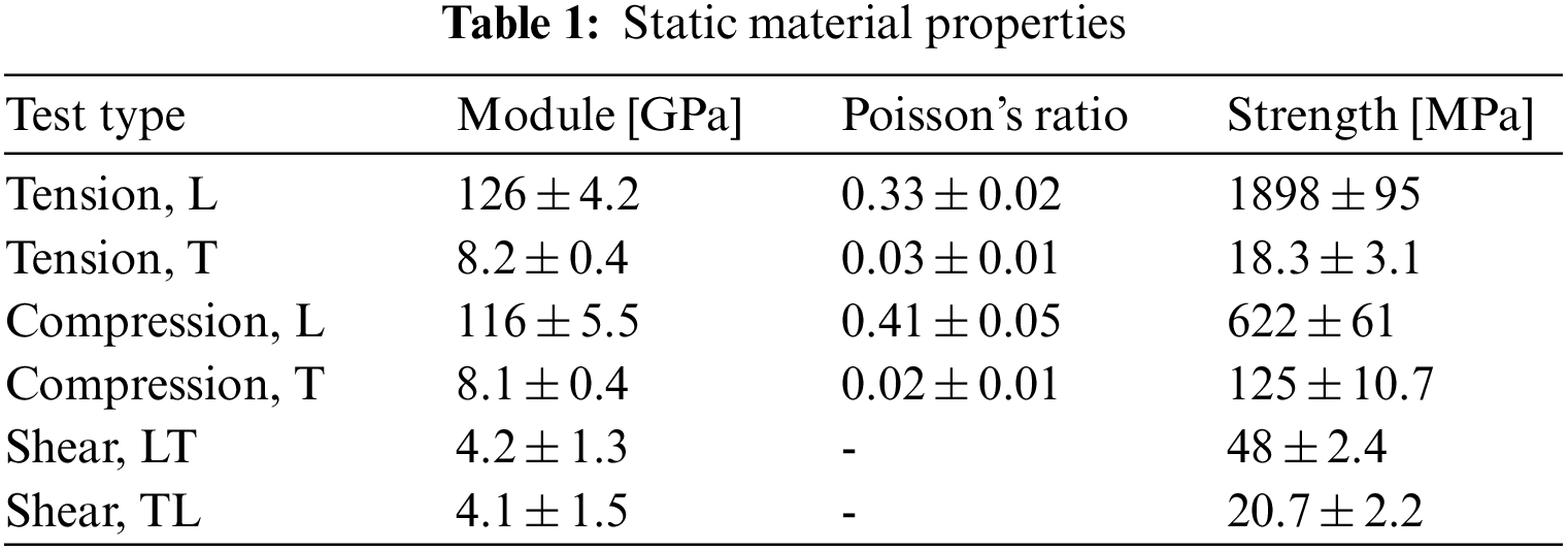
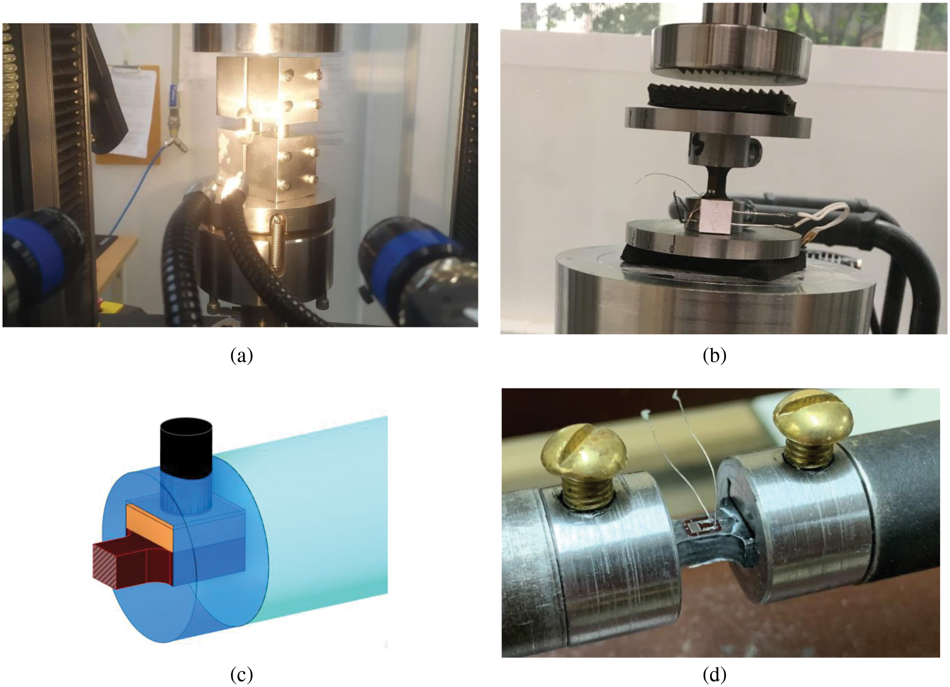
Figure 1: Configurations of compression tests at quasi-static strain-rate (a), intermediate, performed by copra (b) and SHPB (d) with a model of SHPB accessory shown separately (c)
The SHPB tests were performed by a research group at the Research Institute of Mechanics of the Lobachevsky Nizhniy Novgorod State University. For testing of the unidirectional CFRP specimens, a steel incident and aluminum transmitted bar were utilized for the variation of the loading amplitude. See Fig. 2 for the details of the setup. A copper insert was placed at the incident bar as a pulse shaper. Strain pulses in the bars and specimen were measured by strain gauges and recorded using Agilent DSO5014A oscilloscopes. The raw test data was processed by software developed in the LabVIEW environment. Additionally, the specimen deformation was observed by a high-speed camera setup, Phantom VEO 710L, with an acquisition frequency of 100000 fps.
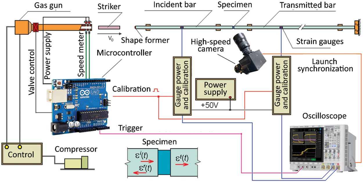
Figure 2: SHPB facility scheme
The specimen dimensions for compressive loading along (a) and perpendicular (b) to the fibers are shown in Fig. 3. The dimensions of the samples were determined to ensure the uniformity of the stress-strain state and the correctness of the failure modes in the gauge area. The specimen–tooling assembly is freely inserted between the bars, Figs. 1c and 1d. Such tooling constrains lateral expansion of the specimen ends and, therefore, prevents damage initiation and localization outside of the gauge length of the specimen.
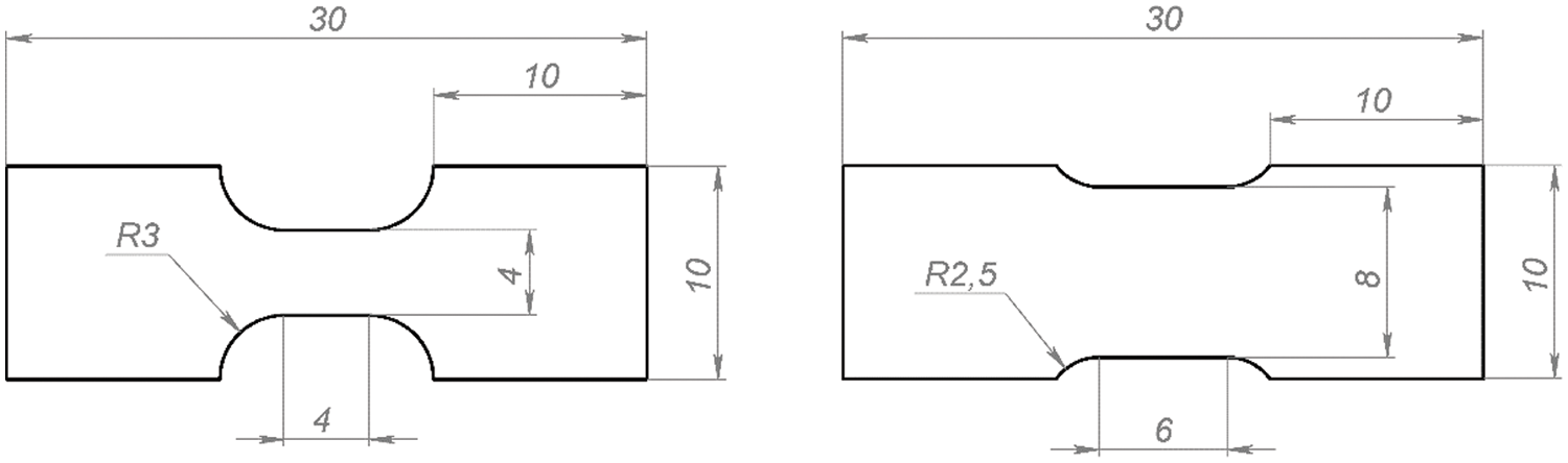
Figure 3: Unidirectional FRP specimens for compression testing by SHPB
Insofar as the SHPB relationships, given by George et al. [1] and shown in Eqs. (1)–(3), which arise from the force equilibrium conditions at the specimen ends, the tooling has to provide an equality of the sum of the incident
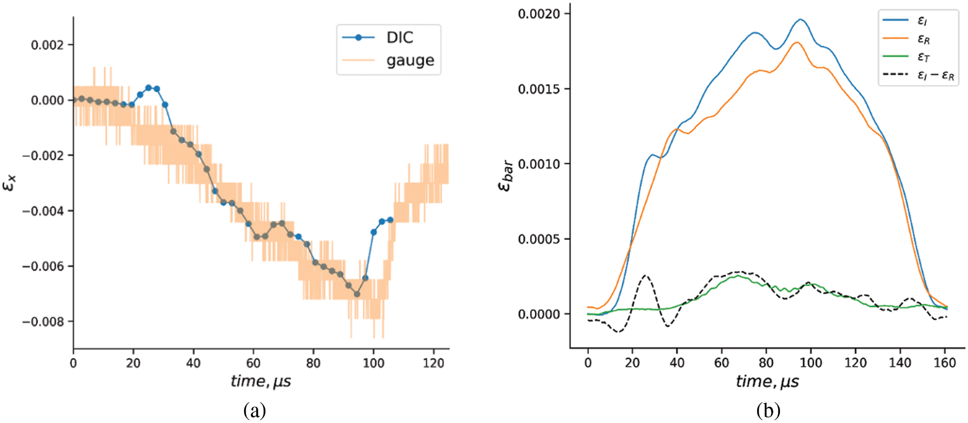
Figure 4: The specimen strains measured by a strain gage and DIC (a), and synchronization of the strain pulses in the measuring bars (b)
The specimen strain
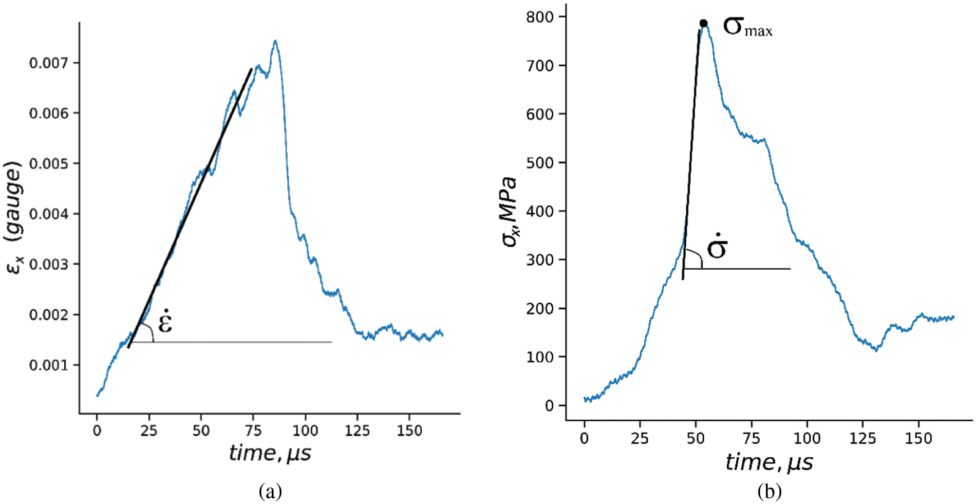
Figure 5: Stress and strain data processing
The deformation of the specimens was simulated in order to justify the dimensions applicable for the SHPB compression tests. The simulation was performed using ABAQUS finite element software. Transversal isotropic material models for elastic behavior and criteria, originally proposed by Hashin [14] for damage analysis, were applied utilizing the material properties given in Table 1 (without consideration of strain rate effects). Hashin’s parameter α from the fiber tensile failure criterion was set to zero since tension does not take place in this experiment. The outline of the FE model is given in Fig. 6. The specimen (1) was placed in the steel tooling (2) between the steel incident (3) and aluminum transmitted (4) bars. Both bars had a diameter of 20 mm and their behavior was considered fully elastic. The plastic behavior of the copper cylinder set at the impacted end of the incident bar as a pulse shaper was simulated by the Johnson-Cook model, as described by Burley et al. [15]. The SHPB system was loaded by a steel impactor, 20 mm in diameter and 150 mm in length. As a result, stress, strain, strain rates and damage parameters throughout the gauge length of the specimens were calculated and compared with the ones calculated by the Eqs. (1)–(3), where the calculated reflected and transmitted pulses were substituted.
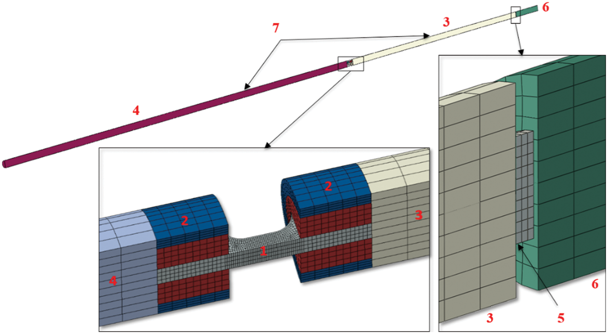
Figure 6: Finite element model of the SHPB outline (cross-section view). 1–specimen, 2–fixture, 3–transmitted bar, 4–incident bar, 5–copper pulse shaper, 6–striker, 7–locations of elements from which strain pulses εI, εT and εR were taken
As an example of the FEA results, Fig. 7 shows the distribution of the fiber compressive damage parameter in the UD specimen subjected to loading along the fibers. Negligible damage is noticed at the loaded face and damage localization is observed in the transition zone to the gauge length of the specimen at the beginning of the loading pulse, 230 μs from the impact (Fig. 7a). The damage at the loaded face is preserved without worsening until the end of the loading pulse (500 μs). The damage in the gauge section is shown to be the prevailing damage, thus the specimen failure appears to be valid (Fig. 7b). In order to further validate specimen geometry, the shapes of the two stress pulses were compared, the first of which was extracted directly from the gauge area of the specimen (Fig. 8, solid curve) and the second was calculated by relationship (1) based on the strain value extracted from one element on the transmitted bar (Fig. 8, dashed curve).
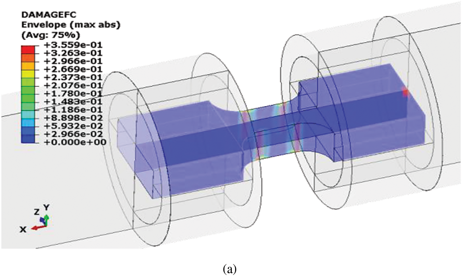
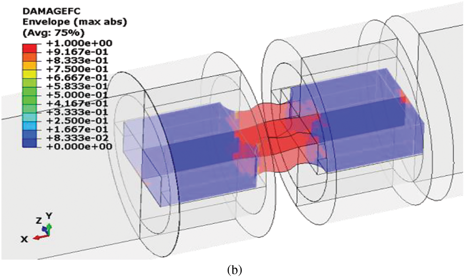
Figure 7: Distribution of the fiber compressive damage parameter in the specimen at damage initiation (a) and after complete failure (b)
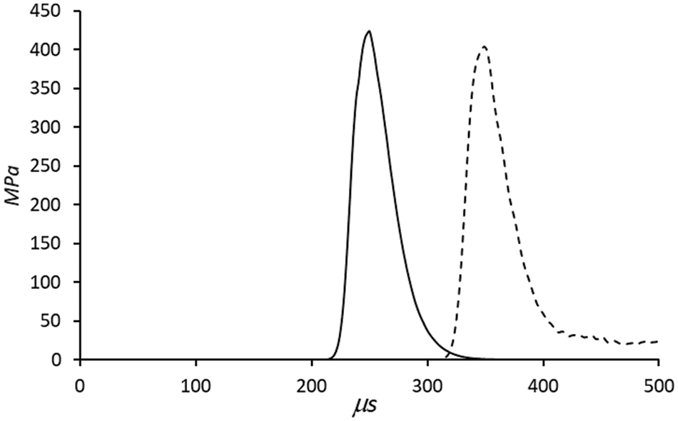
Figure 8: Stress taken from FEA. The solid line shows the average longitudinal stress in the specimen gauge section, the dashed line is calculated from the longitudinal strain in one element in the transmitted bar according to Eq. (1)
4 Experimental Results and Discussion
Fig. 9 shows the characteristic deformation diagrams obtained by compressing unidirectional carbon fiber samples in the direction along (a) and perpendicular (b) to the reinforcing fibers. When loading samples along the fibers, an increase in the strain rate from 0.0001 to 580 s−1 leads to an increase in the stress and deformation of fracture initiation by 42% and 35%, respectively. Qualitatively similar results were obtained in earlier work of Hsiao et al. [16] and presented in later works summarized in the review by Perry et al. [17]. As noted by Hsiao et al. [16], such an increase in the stress and deformation of fracture initiation relative to the values obtained during static tests may be due to the limitation of the development of shear deformation in the plane of the sample due to inertial effects and changes in the shape of the fracture of the sample.
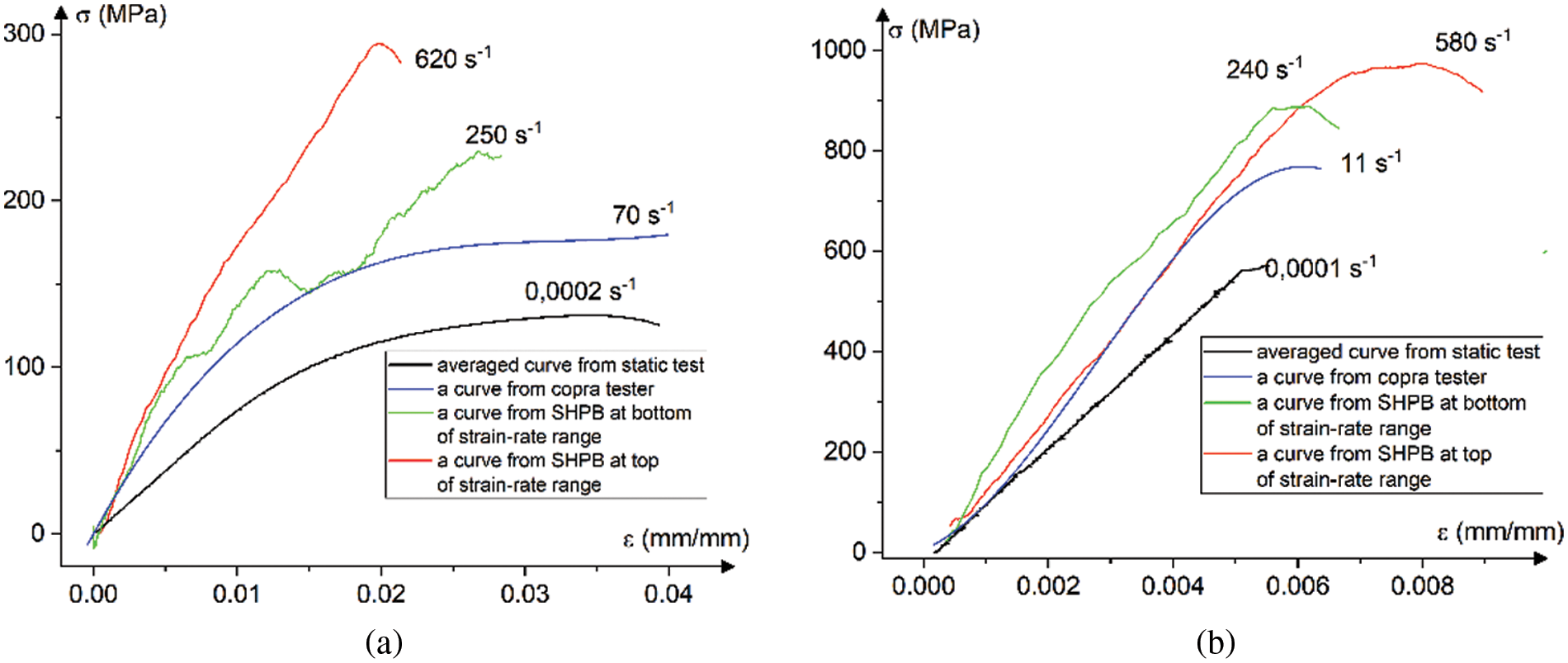
Figure 9: Characteristic deformation diagrams obtained by compressing unidirectional carbon fiber samples in the direction along (a) and perpendicular (b) to the reinforcing fibers
Experimental strain rate dependencies of failure stress under compression for specimens loaded along Xc and across Yc fibers are shown in Fig. 10. Red circles correspond to static values (ST), black squares correspond to the results of tests on copra (С), and blue triangles represent the results of dynamic tests using SHPB. A strain rate increases of up to 500 s−1 leads to more than a 50% increase of the strength for specimens loaded along the fibers (Fig. 9a). The strain rate dependencies of Young modulus under compression along EL and across ET the fiber directions are shown in Fig. 11. The strain rate dependencies of the elastic modulus are rather qualitative in nature, since determiningthe magnitude of the modulus during dynamic tests is associated with significant difficulties due to the accuracy of synchronization of the stress and strain pulses, which, as a rule, are recorded independently as discussed in Ganzenmüller et al. [18].
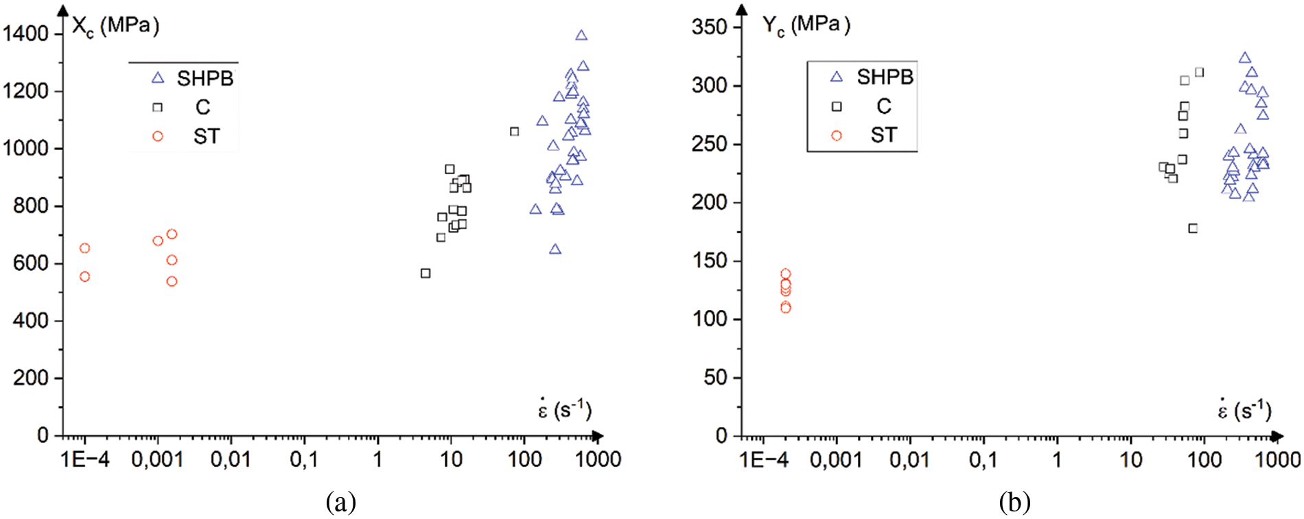
Figure 10: Strain rate dependence of ultimate stresses for specimens loaded along fibers (a) and across fibers (b)
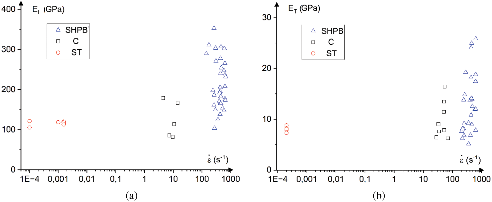
Figure 11: Strain rate dependence of Young modulus for specimens loaded along fibers (a) and across fibers (b)
Fig. 12 shows the development of the process of destruction of the sample under loading in the direction along the fibers. The image capture was carried out in two mutually perpendicular planes (top and side). As a rule, the fracture was initiated in the transition region from the fillets to the working part of the sample and developed within ∼100 microseconds before the loss of the sample resistance to the loading pulse. Fig. 13 compares the specimen stress from the experiment and in the FE-model. Both in the experiment and simulation, stresses are calculated from strains in one of the elements of the transmitted bar according to Eq. (1).
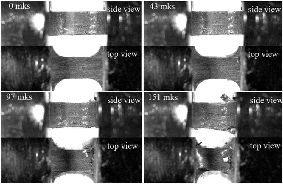
Figure 12: Video registration of specimen deformation process
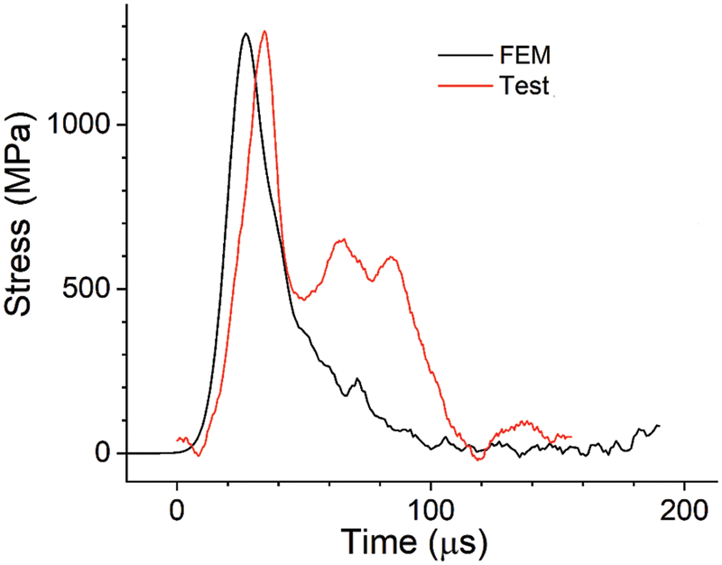
Figure 13: Comparison of specimen stress from the experiment and FE-model
A modification of the SHPB outline was proposed for the dynamic compressive testing of unidirectional FRPs. The dimensions of the specimens were established to ensure specimen strain rates between 100–1500 s−1, providing uniformity of stresses and strains in the gauge area of the specimen during impulse loading. Applicability of this modification was justified by finite element analysis of the stress, strain, strain rate and damage parameters of the specimens. Using the proposed tooling, the strain rate dependencies of the strength of the unidirectional filament wound T700/L113 composite were obtained under compression along and across the fibers.
The following experimental results have been obtained:
1. Compressive strength and elastic modulus increased by 42% and 50%, respectively, when loaded along the fibers.
2. Compressive strength and elastic modulus increased by 58% and 50%, respectively, when loaded across the fibers.
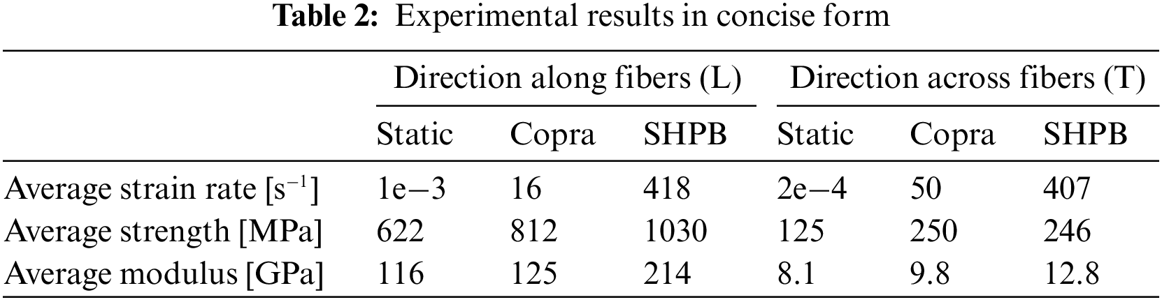
3. The obtained average values for every strain-rate subrange are summed up in Table 2.
A direct comparison of the stress pulses obtained in the experiments and simulations (see Fig. 13) is a good example of how useful a FEM simulation of a real experiment can be. Since this study aims at the process of obtaining a strain-rate dependent model, we implemented a classic Hashin model where the strength value has been chosen to fit the particular specimens, as shown in Fig. 13. The shapes of the pulses are shown to coincide, which leads to the conclusion that the model has been processed correctly. The “trail” visible in the experimental data, as seen in Fig. 13 (minor peaks after the first peak), is related to the presence of debris created during sample failure and is not seen in the modelling results since no such obstacles to complete breakage are produced by the elements.
Acknowledgement: The authors thank Mr. Sergey Gusev, a senior engineer of the Composite Materials and Structures Laboratory of the Centre for Materials Technologies.
Funding Statement: This research was supported by the Russian Science Foundation (Grant No. 21-19-00563, https://rscf.ru/en/project/21-19-00563/). H. M. Sedighi is grateful to the Research Council of Shahid Chamran University of Ahvaz for its financial support (Grant No. SCU.EM1401.98).
Conflicts of Interest: The authors declare that they have no conflicts of interest to report regarding the present study.
References
1. Gray III, G. T. (2000). Classic split-hopkinson pressure bar testing. In: Mechanical testing and evaluation, pp. 462–476. Ohio, USA: ASM International. https://doi.org/10.31399/asm.hb.v08.a0003296 [Google Scholar] [CrossRef]
2. Jia, S., Wang, F., Zhou, J., Jiang, Z., Xu, B. (2021). Study on the mechanical performances of carbon fiber/epoxy composite material subjected to dynamical compression and high temperature loads. Composite Structures, 258, 113421. https://doi.org/10.1016/j.compstruct.2020.113421 [Google Scholar] [CrossRef]
3. Tang, Z. R., Ma, D. W., Zhou, K. D., Zhong, J. L., Ren, J. et al. (2022). The strain rate effect on the compression properties of Basalt/Carbon fiber reinforced composites. Applied Composite Materials, https://doi.org/10.1007/s10443-021-09997-6 [Google Scholar] [CrossRef]
4. Muflikhun, M. A., Higuchi, R., Yokozeki, T., Aoki, T. (2020). Delamination behavior and energy release rate evaluation of CFRP/SPCC hybrid laminates under ENF test: Corrected with residual thermal stresses. Composite Structures, 236, 111890. https://doi.org/10.1016/j.compstruct.2020.111890 [Google Scholar] [CrossRef]
5. Muflikhun, M. A., Yokozeki, T. (2021). Experimental and numerical analysis of CFRP-SPCC hybrid laminates for automotive and structural applications with cost analysis assessment. Composite Structures, 263, 113707. https://doi.org/10.1016/j.compstruct.2021.113707 [Google Scholar] [CrossRef]
6. Muflikhun, M. A., Fiedler, B. (2022). Failure prediction and surface characterization of GFRP laminates: A study of stepwise loading. Polymers, 14(20), 4322. https://doi.org/10.3390/polym14204322 [Google Scholar] [PubMed] [CrossRef]
7. Ploeckl, M., Kuhn, P., Grosser, J., Wolfahrt, M., Koerber, H. (2017). A dynamic test methodology for analyzing the strain-rate effect on the longitudinal compressive behavior of fiber-reinforced composites. Composite Structures, 180, 429–438. https://doi.org/10.1016/j.compstruct.2017.08.048 [Google Scholar] [CrossRef]
8. ASTM-D6641-09 (2009). Standard test method for compressive properties of polymer matrix composite materials using a combined loading compression (CLC) test fixture, vol. 8. ASTM International. https://doi.org/10.1520/D6641_D6641M-16E02 [Google Scholar] [CrossRef]
9. Li, D. S., Duan, H. W., Wang, W., Ge, D. Y., Jiang, L. et al. (2017). Strain rate and temperature effect on mechanical properties and failure of 3D needle-punched carbon/carbon composites under dynamic loading. Composite Structures, 172, 229–241. https://doi.org/10.1016/j.compstruct.2016.11.082 [Google Scholar] [CrossRef]
10. Ramirez, C., Reis, V., Opelt, C., Santiago, R., Almeraya, F. et al. (2019). High strain rate characterization of thermoplastic fiber-reinforced composites under compressive loading. In: Aerospace engineering, pp. 1–24. London, UK: IntechOpen. https://doi.org/10.5772/intechopen.82215 [Google Scholar] [CrossRef]
11. Kim, D. H., Kang, S. Y., Kim, H. J., Kim, H. S. (2019). Strain rate dependent mechanical behavior of glass fiber reinforced polypropylene composites and its effect on the performance of automotive bumper beam structure. Composites Part B: Engineering, 166, 483–496. https://doi.org/10.1016/j.compositesb.2019.02.053 [Google Scholar] [CrossRef]
12. Zhu, Y., Zhang, X., Xue, B., Liu, H., Wen, Y. et al. (2020). High-strain-rate compressive behavior of UHMWPE fiber laminate. Applied Sciences, 10(4), 1505. https://doi.org/10.3390/app10041505 [Google Scholar] [CrossRef]
13. ISO 1268-5:2001 (2001). Fibre-reinforced plastics—Methods of producing test plates—Part 5: Filament winding. [Google Scholar]
14. Hashin, Z. (1980). Failure criteria for unidirectional fiber composites. Journal of Applied Mechanics, 47(2), 329–334. https://doi.org/10.1115/1.3153664 [Google Scholar] [CrossRef]
15. Burley, M., Campbell, J. E., Dean, J., Clyne, T. W. (2018). Johnson-Cook parameter evaluation from ballistic impact data via iterative FEM modelling. International Journal of Impact Engineering, 112, 180–192. https://doi.org/10.1016/J.IJIMPENG.2017.10.012 [Google Scholar] [CrossRef]
16. Hsiao, H. M. M., Daniel, I. M. M. (1998). Strain rate behavior of composite materials. Composites Part B: Engineering, 29(5), 521–533. https://doi.org/10.1016/S1359-8368(98)00008-0 [Google Scholar] [CrossRef]
17. Perry, J. I., Walley, S. M. (2022). Measuring the effect of strain rate on deformation and damage in fibre-reinforced composites: A review. Journal of Dynamic Behavior of Materials, 8, 178–213. https://doi.org/10.1007/s40870-022-00331-0 [Google Scholar] [CrossRef]
18. Ganzenmüller, G. C., Plappert, D., Trippel, A., Hiermaier, S. (2019). A split-hopkinson tension Bar study on the dynamic strength of basalt-fibre composites. Composites Part B: Engineering, 171, 310–319. https://doi.org/10.1016/J.COMPOSITESB.2019.04.031 [Google Scholar] [CrossRef]
Cite This Article
 Copyright © 2023 The Author(s). Published by Tech Science Press.
This work is licensed under a Creative Commons Attribution 4.0 International License , which permits unrestricted use, distribution, and reproduction in any medium, provided the original work is properly cited.
 Downloads
 Citation Tools