
 Submit a Paper
 Propose a Special lssue
 Open Access
ARTICLE
Experimental and Numerical Investigation on High-Pressure Centrifugal Pumps: Ultimate Pressure Formulation, Fatigue Life Assessment and Topological Optimization of Discharge Section
1 School of Engineering, University of Québec in Abitibi-Témiscamingue (UQAT), Rouyn-Noranda, Québec, J9X 5E4, Canada
2 National Engineering School of Monastir, LGM, University of Monastir, Monastir, 5019, Tunisia
3 Department of Applied Mechanical Engineering, College of Applied Engineering, Muzahimiyah Branch, King Saud University, Riyadh, 11421, Saudi Arabia
* Corresponding Author: Haykel Marouani. Email:
(This article belongs to the Special Issue: Structural Design and Optimization)
Computer Modeling in Engineering & Sciences 2023, 137(3), 2845-2865. https://doi.org/10.32604/cmes.2023.030777
Received 22 April 2023; Accepted 10 July 2023; Issue published 03 August 2023
 View Full Text
 Download PDF
Abstract
A high percentage of failure in pump elements originates from fatigue. This study focuses on the discharge section behavior, made of ductile iron, under dynamic load. An experimental protocol is established to collect the strain under pressurization and depressurization tests at specific locations. These experimental results are used to formulate the ultimate pressure expression function of the strain and the lateral surface of the discharge section and to validate finite element modeling. Fe-Safe is then used to assess the fatigue life cycle using different types of fatigue criteria (Coffin-Manson, Morrow, Goodman, and Soderberg). When the pressure is under 3000 PSI, pumps have an unlimited service life of 107 cycles, regardless of the criterion. However, for a pressure of 3555 PSI, only the Morrow criterion denotes a significant decrease in fatigue life cycles, as it considers the average stress. The topological optimization is then applied to the most critical pump model (with the lowest fatigue life cycle) to increase its fatigue life. Using the solid isotropic material with a penalization approach, the Abaqus Topology Optimization Module is employed. The goal is to reduce the strain energy density while keeping the volume within bounds. According to the findings, a 5% volume reduction causes the strain energy density to decrease from 1.06 to 0.66 106 J/m3. According to Morrow, the fatigue life cycle at 3,555 PSI is 782,425 longer than the initial 309,742 cycles.Keywords
Pumps are of great importance and have applications in various industries. All types of pumps have the same functional purpose: adding energy to the liquid to move it along the pipe and increasing the pressure to overcome the force of gravity. They are classified into two major groups: dynamic and positive displacement pumps. Dynamic pumps, such as centrifugal (axial flow, mixed flow, or peripheral) and special-effect (jet or electromagnetic), maintain a steady fluid flow. Positive displacement pumps, such as reciprocating (piston and plunger, or diaphragm) and rotary (single or multiple rotors), contain individual portions of fluid enclosed before moving along. Despite the high diversity of types of pumps, centrifugal pumps have far more applications than the other types. For instance, over 80% of petrochemical units are centrifugal [1]. They are widely used in many other industries, such as food and beverages, chemistry, pulps, slurry, agriculture and power generation [2]. They work far better and have a wider operating range than other pumps. Indeed, where centrifugal pumps are ineffective, such as when pumping biphasic or high-viscosity fluids, the other various types of pumps are then utilized [3,4]. By employing centrifugal force to accelerate the liquid, centrifugal pumps first create pressure before lowering it internally. Before passing through the impeller blades, the fluid first enters the suction nozzle, then flows towards the impeller eye. The impeller transfers energy to the fluid moving from the impeller’s eye through the vane channel in the direction of the impeller’s outer diameter as it rotates at a rate corresponding to the driver (electric motor, turbine, or diesel generator) of the pump. Various standards have been developed for centrifugal pumps, such as API 610, API 685, ANSI/ASME B 73.1, ANSI/ASME B 73.2, ISO 5199, DIN 24255... These standards are devoted to the design, selection, testing and operation conditions of centrifugal and other pumps.
Despite these standards and due to extreme and variable work conditions, some mechanical parts of pumps fail. Indeed, fatigue failure is part of industrial machinery, and pump parts are no exception [5]. Therefore, estimating the fatigue life in pump elements is essential to avoid unexpected failure. For these reasons, researchers have studied centrifugal pumps theoretically and experimentally, as well as through numerical simulation, and produced valuable research findings that have successfully aided in the advancement of centrifugal pumps technology and products [6–11]. Fatigue life prediction approaches have been continuously improved in response to the requirement for accurate structure life forecasts and the growing understanding of the fatigue phenomenon. These approaches can be categorized according to three major criteria [12]. The first ones are based on stress formulation, such as the models developed by Gerber (1874), Basquin (1910), Goodman (1930), Soderberg (1930), Morrow (1965), Walker (1970)... Stress criteria are applicable in high-cycle fatigue life prediction work. If the material enters the yield stage, the results predicted by the stress criteria tend to be conservative. The second ones are based on strain formulation, such as the models developed by Coffin and Manson (1954), Morrow (1969), Manson and Halford (1981)... The strain life criteria are classically used for low cycle fatigue when the stress level is high and the number of cycles to failure is low. The third ones are based on energetic formulations or stress/strain criteria such as SWT (1970), Lorenzo and Laird (1984), Golos (1987), Zhu (2012), Ince (2015), Correia (2017)... Energy criteria consider that the damage to the material is caused by the accumulation of strain energy in the material. When the critical value of energy is reached, the material fails.
Fatigue life assessment highlights the weak section of the part or structure that harmfully decreases its life cycle. Fortunately, alternatives exist to fix these shortcomings by oversizing the part, changing the body material, or optimizing the shape by topology optimization. Oversized parts are linked to more volume, weight, expense, and probably less performance. Swapping the part material is not an obvious decision because of manufacturing process constraints and mechanical and thermal property requirements. The actual efforts investigated by engineering are focused on topology optimization. In order to maximize defined system performance, a mathematical technique optimizes material placement inside a given design space for a particular combination of loads, boundary conditions, and constraints. In contrast to shape and sizing optimization, topology optimization deals with the design's ability to take on any shape within the design space rather than dealing with predefined configurations. There are different topology optimization methods in the literature, including the Solid Isotropic Material with Penalization (SIMP) method [13,14], the ground structure method [15,16], the bidirectional evolutionary structural optimization method [17,18], the level-set method using a shape derivative [19,20], the parameterized level-set method using radial basis functions [21,22], the topological derivative method [23,24] and the phase-field approaches [25,26]. With the help of these methods, some ‘on-demand’ mechanical properties (such as strength or deflection) can be improved concerning defined constraints (such as volume). Over the past decade, researchers have proposed different methodologies by adapting or combining some characteristics of these strategies [27]. Nonetheless, each of them still has some restrictions.
In this paper, we present our investigation work to improve the fatigue life of industrial centrifugal pumps. Our work focuses on a specific pump component, which is the discharge section of the pump, which is made of ductile iron. First, experimental measurements and numerical simulation allow us to formulate a generic expression of the limit pressure of the pump as a function of the pressure and the geometry of the discharge section. Then, the numerical modeling allows us to analyze the fatigue life of this discharge section according to different criteria. Finally, topological optimization is used to modify the geometry of the relief section in order to improve fatigue life.
2 Experimental Set-Up and Analysis Methodology
The industrial partner for this study is called Technosub (https://www.technosub.net). It is a benchmark company in Canada for pumping solutions. It has the expertise to design and fabricate parts and complete packages for the specific needs of its customers. Their products range from submersible pumps, engine-driven pumps, end-suction centrifugal pumps, vertical turbine pumps, submersible motors, booster pump systems, barges for pumps, water treatment systems, and multistage high-pressure pumps. In this work, we strive to improve the fatigue life cycle of the MH-series of multistage high-pressure pumps by defining an ultimate pressure model, investigating the fatigue life cycle under different criteria, and making a topological optimization.
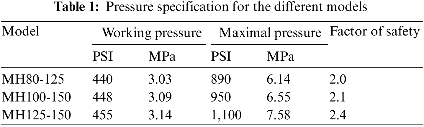
This study focuses on three configurations of high-pressure multistage centrifugal pumps, referred to as MH80-125, MH100-150, and MH125-150 (Fig. 1). The first digits refer to the suction diameter, and the last refer to the discharge diameters. Table 1 resumes the working pressure and the maximal allowed pressure. As recommended by different standards, the factor of safety, i.e., the ratio of working pressure by maximal pressure, should be greater than 2.
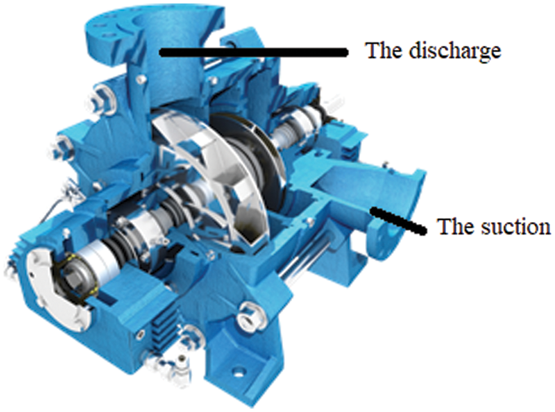
Figure 1: Sectional view of Technosub high-pressure multistage pump (MH series)
The experimental, analytical and numerical methodologies are described in the following flowchart (Fig. 2). For each MH pump, we start with the definition of the design parameters. We identify the critical parts to be investigated (subject to fatigue crack or bursting) according to the company feedback. The selected components are subject to mechanical testing to collect their mechanical properties. As only the selected parts will be numerically simulated, we investigate the boundary and load equivalent conditions (pressure on bolts, assembly conditions, water pressure...). The first step concludes that the discharge module is to be investigated.
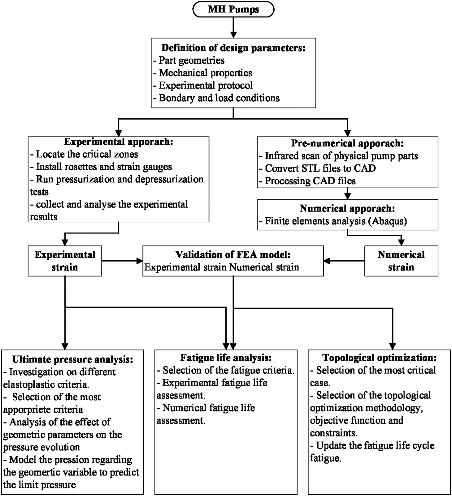
Figure 2: Investigation methodology flowchart
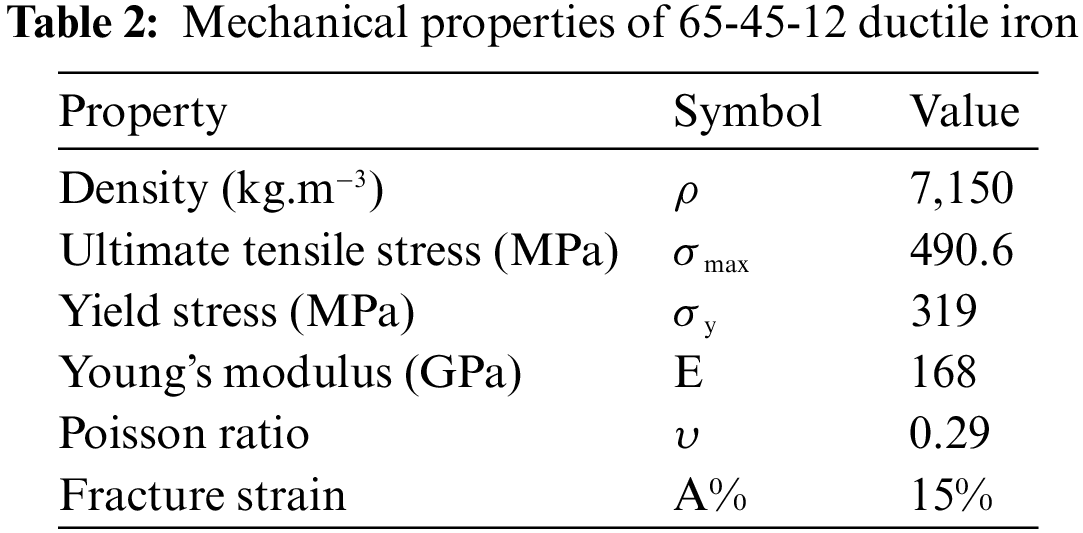
The discharge section is made of a ductile iron designed as grade 65-45-12 according to the ASTM A536 standard. Grade 65-45-12 is iron with nodular graphite and small amounts of pearlite. It has great machinability, good surface finishes, impact strength, and good fatigue properties. Tensile tests are performed to assess the mechanical properties according to the ASTM A370 standard (Mechanical Testing of Steel Products). The material properties are resumed in Table 2.
The second step in our investigation protocol is to collect the experimental strain in some specific location to validate the finite element analysis later. For this purpose, critical zones on the discharge part body are identified. We then install rosettes and strain gauges to collect the experimental strain (Fig. 3). Finally, different pressurization and depressurization tests are made.
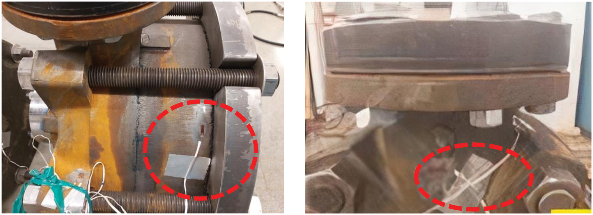
Figure 3: Strain gauge and rosette placement in discharge module
During the pressurization and depressurization tests, the experimental strain of the pumps in several directions and at different pressure conditions are determined from the pressure cycles imposed on its discharge sections. The pump is run under dynamic loads at a rotational speed of 1,800 rpm, a flow rate ranging from 151 to 3,785 liters per minute, and a pressure ranging from 1 to 19.45 MPa. The pressure starts at 1 MPa and is doubled plus 10% each next minute (Fig. 4). The depression follows a linear decrease at the end of the cycle. The choice of pressure cycle is based on the experimental protocol developed by combining many standards usually applied for the sizing of pumps, such as ANSI/API 610:1995, ASME B73.1:2001, ISO 9906:2012, and ISO 19688:2019.

Figure 4: Pressurization and depressurization cycle
The third step is to prepare the finite element analysis by assessing the 3D draft of the discharge part body. Infrared scans are performed, and the corresponding STL files are converted to STP files. This extension is supported by Abaqus, and the process sometimes requires some manual correction to fix the surface generation problems that may occur.
The fourth step is to perform a finite element analysis and to compare the numerical results with the experimental ones (see Section 3). Once the numerical model is validated, three types of investigation are done. The first one is the ultimate pressure modeling (Section 4), the fatigue life analysis (Section 5), and the topological optimization (Section 6).
Instead of using the CAD files of the designed pump before manufacturing, an infrared scan of each pump part is used to have more accurate dimensions. Indeed, the casting process and some finishing operations slightly affect the initial dimensions of the pumps and induce some dimensional errors. The scan files (.STL) are converted to an STP format that can be used by Abaqus software. The boundary conditions (Fig. 5) are applied following the actual conditions in terms of pressure applied for closing the shaft cover, the tightening torque, the bolt torque... According to the literature [28] and numerical trials, the ten-node tetrahedral element with four integration points, C3D10, offers the best results (Fig. 6). The mesh sizes are 17, 18, and 22 mm for the MH80-125, MH100-150, and MH125-150 pumps, respectively.

Figure 5: Summary of boundary conditions

Figure 6: MH80-125 meshing
In order to validate the finite element model, a comparison between the numerical strain and the experimental one at the strain gauge locations is performed. For example, Fig. 7 shows the equivalent location of one strain gauge used in experiments. The numerical results show a strain of 0.000579758 at 1,500 PSI (10.342 MPa), which perfectly matches the experimental value of 0.000579. The comparison of different data shows a good accordance between experiments and numerical results with an error of less than 2%.

Figure 7: (a) Experimental location of the strain gauge (b) numerical results (pressure = 1500 PSI)
This section describes the ultimate pressure assessment using three different elastoplastic criteria: The Tresca yield, the equivalent plastic strain, and the strain energy density.
The Tresca yield criterion (Eq. (1)) is based on the maximum shear stress theory. It is also called the maximum shear stress criterion. This theory predicts the failure of a material to occur when the absolute maximum shear stress (τmax) reaches the stress that causes the material to yield in a simple tension test.
where
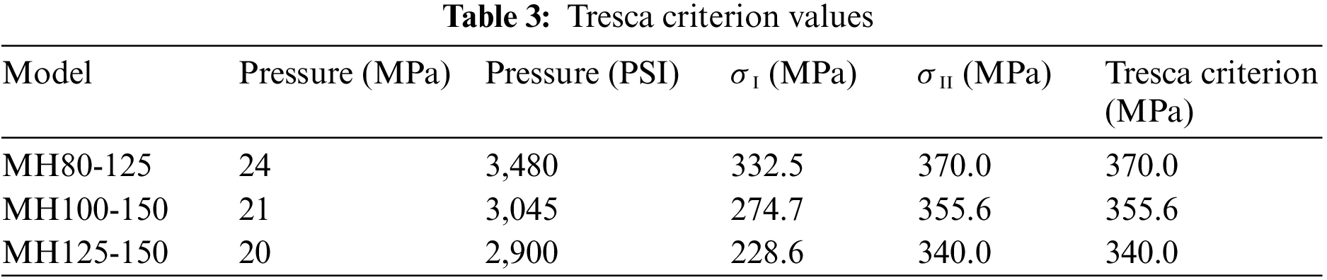
Fig. 8 shows a 2D stress distribution in the discharge sections of the investigated pumps based on the Tresca criterion and the experimental results. The maximum values are 370.02 MPa at 24.5 MPa, 355.56 MPa at 21 MPa, and 339.97 MPa at 20 MPa for MH80-125, MH100-150, and MH125-150, respectively (Table 3). The hexagon represents the threshold stresses that can be reached at the beginning of the operation. These out-values can be explained by the plastic strain of the structure caused by both shear stresses and the motion of the planes of atoms. Similar observations were made by the previous author in [29].
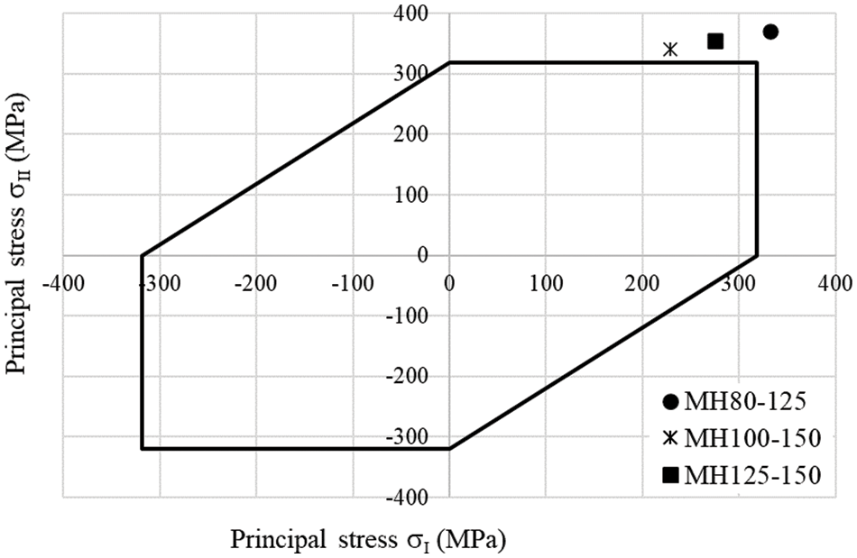
Figure 8: In-plane stress distribution according to Tresca yield criterion
The equivalent plastic strain criterion [30,31] is based on the specific Hollomon plasticity model given by:
where σ is the true stress, εT is the true total strain, k is the strength coefficient, and n is the strain-hardening exponent.
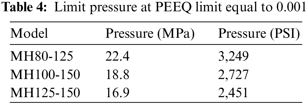
Fig. 9 shows the equivalent plastic strain as a function of pressure for each pump model. The equivalent plastic strain, called PEEQ in Abaqus, defining the beginning of plasticity is chosen as equal to 0.001. A projection on the pressure axis for this limit allows us to determine the limit pressure using the PEEQ criterion (Table 4).

Figure 9: Evolution of pressure vs. PEEQ
The Elastic Strain Energy Density (ESED) is an energetic local approach validated as a method to investigate both fractures in static conditions and fatigue failure [32,33]. The following expression gives the elastic strain energy density for a linear elastic isotropic material:
where σij is the Cauchy stress tensor components.
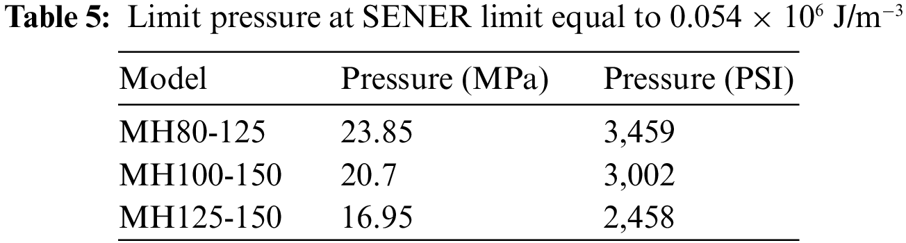
The FEA investigation shows that the ESED limit, which defines the beginning of plasticity, is equal to 0.54 × 10⁶ J/m3. Fig. 10 shows the ESED as a function of pressure for each pump model. The strain energy density, called SENER in Abaqus, that defines the beginning of plasticity is chosen as equal to 0.54 × 10⁶ J/m3. A projection on the pressure axis for this limit allows us to determine the limit pressure using the ESED criterion (Table 5).
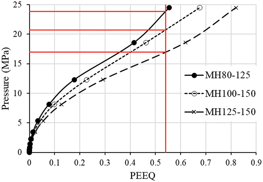
Figure 10: Evolution of pressure vs. SENER
Tables 3–5 give the ultimate pressures for the three investigated multistage high-pressure centrifugal pumps based on three criteria. The lowest values are given by the PEEQ criterion, so it is considered the most suitable one for formulating the limit pressure relationship. Based on these results, we plot the evolution of the experimental strain function of the pressure (Fig. 11). A sensitivity analysis shows that the strain expression is linearly dependent on the pressure and the discharge section. In other words, the strain can be expressed as:

Figure 11: Experimental strain function of the pressure
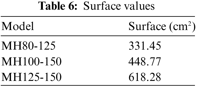
where S is the lateral surface of the discharge section, as described in Table 6.
The generalized reduced gradient is used to identify these constants (Table 7). This method is an extension of the reduced gradient method [34,35]. The comparisons between the experimental and analytical model curves are depicted in Fig. 12.
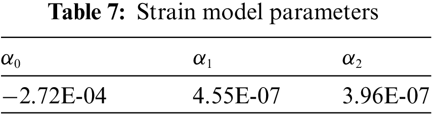

Figure 12: Validation of the analytical model: (a) MH80-125, (b) MH100-150, (c) MH125-150
The analytical model (Eq. (5)) is now arranged to express the limit pressure that corresponds to a limit strain of 0.00186:
This formulation expresses the ultimate pressure for any pump, even that not included in this study, as a function of the strain and the lateral discharge surface.
There are numerous methods to estimate fatigue life. This section compares four fatigue life prediction approaches: two strain life criteria (Coffin–Manson and Morrow) and two stress life criteria (Goodman and Soderberg).
The Coffin–Manson formula is:
where
The strain amplitude is computed according to the following formula:
where
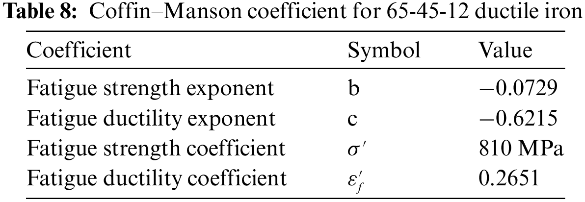
The 65-45-12 ductile iron coefficients for the Coffin-Manson formula are resumed in Table 8.
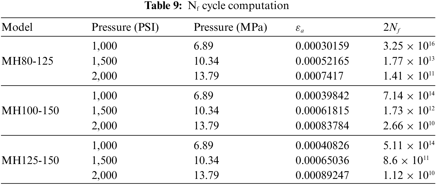
Based on the experimental data, the life cycle can be analytically estimated according to Eq. (7), as shown in Table 9. The results show that the fatigue life of these discharge sections is in the unlimited life zone up to a cyclic pressure equal to 2000 PSI (Nf > 107 cycles).
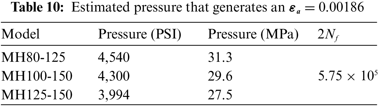
As we cannot experimentally reach higher pressure, we use the FEA to define the pressure that generates a strain amplitude of 0.00186 for each pump (Table 10) to investigate fatigue life further. The value of 0.00186 corresponds to the beginning of plasticity for the discharge section. In this case, the fatigue life cycle is equal to 2.875 × 10⁵ according to the Coffin–Manson criteria.
The fatigue life assessment is now performed using Fe-Safe software, which is directly interfaced with Abaqus. The finite element model, already validated, is used. The tested criteria are Morrow, Goodman, and Soderberg.
The Morrow criteria express the total strain amplitude and the fatigue life as:
where
Goodman and Soderberg models can be expressed using Marin’s equation:
where Sa is the alternating stress for the targeted mean stress level and specific fatigue life, Sm is the mean stress, Sa0 corresponds to the zero-mean-stress alternating stress, and Su is the ultimate tensile strength. Actually, k is a constant defined as follows:
where Sy is the yield strength.
Figs. 13–16 represent the fatigue life ranges of the pump bodies. For the presentation of the results, an inverted rainbow spectrum is used (red represents the lowest fatigue strength). The values on the data range represent the number of times the cycle repeats. Therefore, to assess the number of cycles N, it is necessary to put the number of times the cycle is repeated as a power of 10.
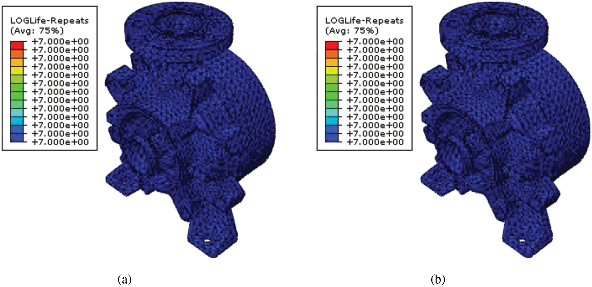
Figure 13: Fatigue life ranges of the MH80-125, Pressure 3,555 PSI: (a) Soderberg, (b) Goodman

Figure 14: Fatigue life ranges of the MH100-150, Pressure 3,555 PSI: (a) Soderberg, (b) Goodman

Figure 15: Fatigue life ranges of the MH125-150, Pressure 3,555 PSI: (a) Soderberg, (b) Goodman

Figure 16: Fatigue life ranges using the Morrow criteria for a pressure of 3,555 PSI: (a) MH80-125, (b) MH100-150, (c) MH125-150
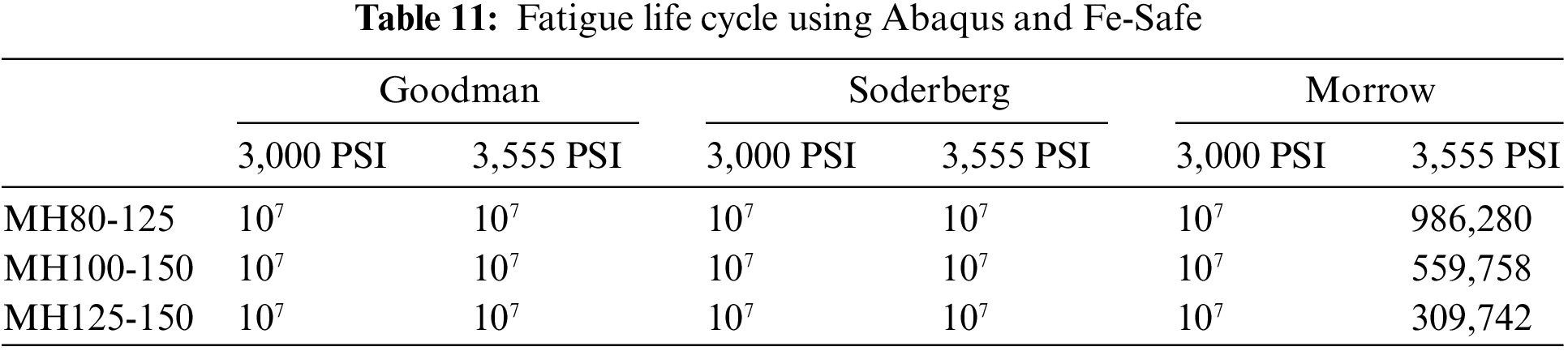
The numerical results show that for a pressure of 3,000 PSI (20.7 MPa), the three pumps are in their comfort zone (i.e., they have an unlimited service life of 107 cycles), whatever the used fatigue life criterion. Even at 3,555 PSI (24.5 MPa), the unlimited service life remains, except when using the Morrow criteria (Figs. 13–16). Indeed, it is noticed that it is the most critical fatigue model because it takes into account the average stress. Regarding the low-cycle fatigue zone, the MH125-150 and MH100-150 models are the first to be deformed plastically after the application of a pressure of 3555 PSI with a low number of cycles of 309,742 and 559,758, respectively, while for the MH80-125 model, the cycle number is 986,280 before breaking (Table 11).
The fatigue life cycle study and the finite element analysis under dynamic solicitations show that MH125-150 represents the most critical case study with the lowest fatigue life cycle. The stress concentration areas for the pump are located at the back of the discharge section around the hub (Fig. 17). These areas represent the weakness section that negatively affects its life cycle. In order to improve the number of cycles, three approaches are available: oversizing the whole pump body, changing the body material, or optimizing the shape by topology optimization. Topological optimization will remove the superfluous material and guarantee proper functioning in specific working conditions.
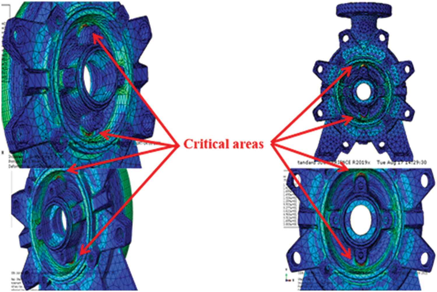
Figure 17: Location of the critical areas defining the weakness section
The SIMP method is a popular topological optimization approach and is already implemented in Abaqus. It simply distributes the available material to the space depending on the finite element analysis results. Different studies suggest using the strain-energy-based criterion to develop a topology optimization algorithm [36,37]. Indeed, an element subjected to a load undergoes strains, sometimes irreversible. In this mechanism and for gradual loading, the work materialized by this load is converted into internal work, i.e., strain energy. Assuming there is no thermal energy loss, this energy is stored in the material, and the internal energy per unit volume is defined as the density of the strain energy. The FEA under different pressure shows that the elastic strain energy density (defined in Abaqus as SENER output) can reach a value of 1.06 × 10⁶ J/m3 for the MH125-150 pump locally. The comfort zone, defined in the previous section, corresponds to a value of SENER less than 0.54 × 10⁶ J/m3. For these reasons, the optimization objective will be the SENER output. The calculations are done using the Abaqus Topology Optimization Module (ATOM), which uses the SIMP algorithm with the strain energy density of the material. The objective function is to minimize the strain energy density subject to a volume constraint.
The optimization process converges after 14 iterations (Fig. 18). Fig. 19 depicts the gradual modification of the volume distribution among the iterations. The results show that the SENER declines from 1.06 × 10⁶ J/m3 to 0.66 × 10⁶ J/m3 with a reduction in the volume of 5%. According to Morrow, the fatigue life cycle at 3,555 PSI reaches 782,425 cycles instead of the initial 309,742 cycles.
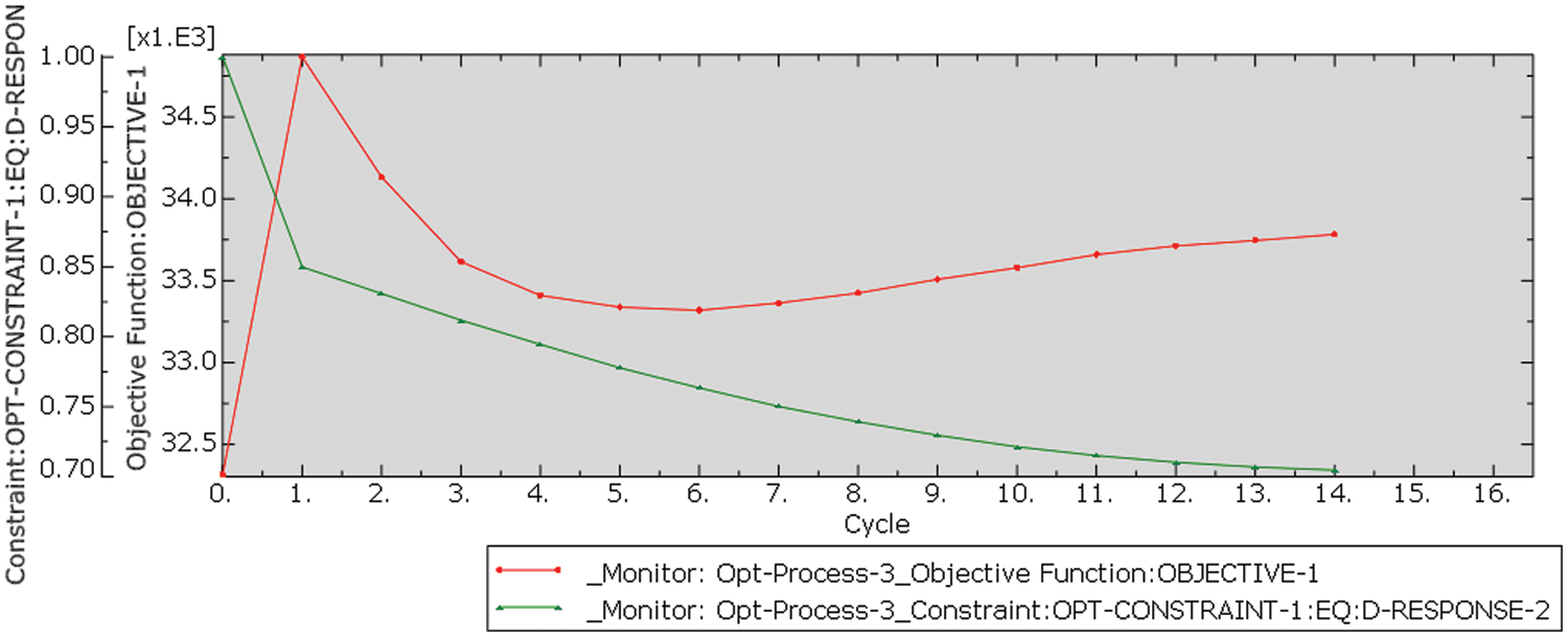
Figure 18: Evolution of objective function and constraint (ATOM)
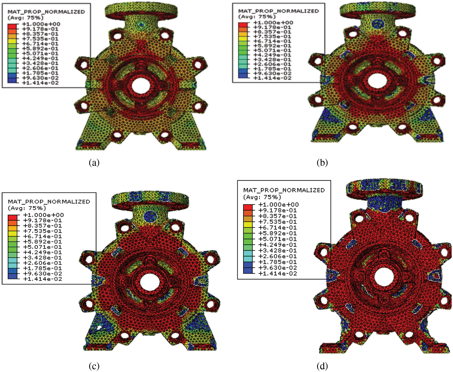
Figure 19: Evolution of volume distribution after (a) 2 iterations, (b) 6 iterations, (c) 10 iterations, and (d) 14 iterations
The fatigue life assessment of centrifugal pump parts is a crucial research area to improve the life cycle of such a major machine for industry and to increase its performance. The literature has focused on parts such as the impeller, the fastener, the shaft and the runner. However, according to our industrial partner feedback, Technosub company, the discharge section represents the weak component of their high-pressure centrifugal pumps. Three models are investigated experimentally and numerically. Indeed, an experimental protocol is established to assess the strain at critical locations of the discharge section under dynamic loads. Finite element analysis using Abaqus and Fe-Safe is performed to improve our understanding of the discharge section behavior. Our investigation starts by modeling the ultimate pressure using three different elastoplastic criteria: The Tresca yield, the equivalent plastic strain and the strain energy density. Findings indicate that the equivalent plastic strain criteria are more suitable. A sensitivity analysis shows that the strain expression is linearly dependent on the pressure and discharge section. A general formulation is then established to express the ultimate pressure for each pump and any other pump not included in this study as a function of the strain and the lateral discharge surface. Fatigue life analysis is performed using the Fe-Safe suite. The Coffin–Manson, Morrow, Goodman and Soderberg criteria are used. The experimental pressure, which reaches 3000 PSI, shows that the pumps have an unlimited service life of 107 cycles. These results are in good accordance with numerical ones. However, for a pressure of 3,555 PSI, Morrow criteria denotes a decrease in fatigue life cycles equal to 309,742, 559,758 and 986,280 for MH125-150, MH100-150, and MH80-125, respectively. According to these findings, optimization topology is applied to the MH125-150 pump. The Abaqus Topology Optimization Module, which uses the solid isotropic material with a penalization method, is used: The objective function is to minimize the strain energy density subject to a volume constraint. The results show that the strain energy density declines from 1.06 × 10⁶ J/m3 to 0.66 × 10⁶ J/m3 with a reduction in the volume of 5%. According to Morrow, the fatigue life cycle at 3,555 PSI reaches 782,425 cycles instead of the initial 309,742 cycles.
Acknowledgement: The authors extend their appreciation to the Researchers Supporting Project number (RSPD2023R698), King Saud University, Riyadh, Saudi Arabia for funding this research work.
Funding Statement: Pr. Y. F. received the funds from the Researchers Supporting Project Number (RSPD2023R698), King Saud University, Riyadh, Saudi Arabia.
Author Contributions: The authors confirm contribution to the paper as follows: study conception and design: A.S. Adam, H. Mrad, H. Marouani; data collection: A.S. Adam, H. Mrad; analysis and interpretation of results: A.S. Adam, H. Mrad, H. Marouani, Y. Fouad; draft manuscript preparation: A.S. Adam, H. Marouani. All authors reviewed the results and approved the final version of the manuscript.
Availability of Data and Materials: Data are available on request.
Conflicts of Interest: The authors declare that they have no conflicts of interest to report regarding the present study.
References
1. Girdhar, P., Moniz, O., Mackay, S. (2004). Practical centrifugal pumps. Amsterdam: Elsevier. [Google Scholar]
2. Girdhar, P., Moniz, O., Mackay, S. (2005). Centrifugal pump operation and characteristics. In: Practical centrifugal pumps, Amsterdam: Elsevier. [Google Scholar]
3. Mohammadi, Z., Heidari, F., Fasamanesh, M., Saghafian, A., Amini, F. et al. (2023). Centrifugal pumps. In: Transporting operations of food materials within food factories: Unit operations and processing equipment in the food industry, pp. 155–200. Amsterdam: Elsevier. [Google Scholar]
4. Karassik, I., Messina, J., Cooper, P., Heald, C. (2008). Pump handbook. New York: McGraw-Hill. [Google Scholar]
5. Ocampo, R. (2008). Fatigue failures in pumps—Part 1. World Pumps, 2008(500), 42–45. [Google Scholar]
6. Xie, Z., Shi, W., Tian, Q., Zheng, Y., Tan, L. (2021). Fatigue life assessment and damage investigation of centrifugal pump runner. Engineering Failure Analysis, 124(1), 105256. [Google Scholar]
7. Isametova, M., Nussipali, R., Isametov, A. (2019). The simulation of the service life of the rotary shaft of a centrifugal pump. MATEC Web of Conferences, 287, 1–6. [Google Scholar]
8. Tuo, Y., Zhang, G., Meng, Y. (2020). Fatigue life research and reliability analysis of ASP pump rotor. Journal of Mechanical Strength, 42(1), 74–80. [Google Scholar]
9. Wang, F. J., Qu, L. X., He, L. Y., Gao, J. Y. (2013). Evaluation of flow-induced dynamic stress and vibration of volute casing for a large-scale double-suction centrifugal pump. Mathematical Problems in Engineering, 2013, 764812. [Google Scholar]
10. Yogesh, P., Raghavan, R., Vigneshkumar, R., Harish, R., Praveenkumar, K. (2018). Reliability improvement of cooling water pump. International Journal of Mechanical and Production Engineering Research and Development, 8(3), 755–766. [Google Scholar]
11. Liu, S. J., Liang, G. Z. (2015). Failure modes of space shuttle main engine high-pressure fuel turbopump. Journal of Aerospace Power, 30(3), 611–626. [Google Scholar]
12. Yang, S., Yang, L., Wang, Y. (2020). Determining the fatigue parameters in total strain life equation of a material based on monotonic tensile mechanical properties. Engineering Fracture Mechanics, 226(10), 106866. [Google Scholar]
13. Duysinx, P., Bendsøe, M. P. (1998). Topology optimization of continuum structures with local stress constraints. International Journal for Numerical Methods in Engineering, 43(8), 1453–1478. [Google Scholar]
14. Wang, Q., Han, H., Wang, C., Liu, Z. (2022). Topological control for 2D minimum compliance topology optimization using SIMP method. Structural and Multidisciplinary Optimization, 65(1), 38. [Google Scholar]
15. Deng, H., To, A. C. (2020). Linear and nonlinear topology optimization design with projection-based ground structure method (P-GSM). International Journal for Numerical Methods in Engineering, 121(11), 2437–2461. [Google Scholar]
16. Li, Z., Luo, Z., Zhang, L. C., Wang, C. H. (2021). Topological design of pentamode lattice metamaterials using a ground structure method. Materials and Design, 202, 109523. [Google Scholar]
17. Shobeiri, V. (2020). Bidirectional evolutionary structural optimization for nonlinear structures under dynamic loads. International Journal for Numerical Methods in Engineering, 121(5), 888–903. [Google Scholar]
18. Li, Y., Zhou, G., Chang, T., Yang, L., Wu, F. (2022). Topology optimization with aperiodic load fatigue constraints based on bidirectional evolutionary structural optimization. Computer Modeling in Engineering & Sciences, 130(1), 499–511. https://doi.org/10.32604/cmes.2022.017630 [Google Scholar] [CrossRef]
19. Burman, E., Elfverson, D., Hansbo, P., Larson, M. G., Larsson, K. (2018). Shape optimization using the cut finite element method. Computer Methods in Applied Mechanics and Engineering, 328(1), 242–261. [Google Scholar]
20. Dunning, P. D., Kim, H. A. (2015). Introducing the sequential linear programming level-set method for topology optimization. Structural and Multidisciplinary Optimization, 51(3), 631–643. [Google Scholar]
21. Wei, P., Liu, Y., Li, Z. (2020). A multi-discretization scheme for topology optimization based on the parameterized level set method. International Journal for Simulation and Multidisciplinary Design Optimization, 11, 1–10. [Google Scholar]
22. Jiang, Y., Zhao, M. (2020). Topology optimization under design-dependent loads with the parameterized level-set method based on radial-basis functions. Computer Methods in Applied Mechanics and Engineering, 369(2), 113235. [Google Scholar]
23. Norato, J. A., Bendsøe, M. P., Haber, R. B., Tortorelli, D. A. (2007). A topological derivative method for topology optimization. Structural and Multidisciplinary Optimization, 33(4–5), 375–386. [Google Scholar]
24. Castañar, I., Baiges, J., Codina, R., Venghaus, H. (2022). Topological derivative-based topology optimization of incompressible structures using mixed formulations. Computer Methods in Applied Mechanics and Engineering, 390(2), 114438. [Google Scholar]
25. Habibian, A., Sohouli, A., Kefal, A., Nadler, B., Yildiz, M. et al. (2021). Multi-material topology optimization of structures with discontinuities using Peridynamics. Composite Structures, 258(2), 113345. [Google Scholar]
26. Marino, M., Auricchio, F., Reali, A., Rocca, E., Stefanelli, U. (2021). Mixed variational formulations for structural topology optimization based on the phase-field approach. Structural and Multidisciplinary Optimization, 64(4), 2627–2652. [Google Scholar]
27. Sigmund, O., Maute, K. (2013). Topology optimization approaches: A comparative review. Structural and Multidisciplinary Optimization, 48(6), 1031–1055. [Google Scholar]
28. Hu, G., Deng, S., Wang, G., Wang, M., Xie, M. (2022). Corrosion crack’s propagation analysis and fatigue life prediction of the cylinder of 6000HP hydraulic fracturing pump. Engineering Failure Analysis, 141(1), 106652. [Google Scholar]
29. Aleksandrova, N. (2019). Efficiency of the Tresca yield criterion in modeling of annular plates with rigid constraint. Applied Mathematical Modelling, 75(4), 371–384. [Google Scholar]
30. Gruben, G., Hopperstad, O. S., Borvik, T. (2012). Evaluation of uncoupled ductile fracture criteria for the dual-phase steel Docol 600DL. International Journal of Mechanical Sciences, 62(1), 133–146. [Google Scholar]
31. Dai, J., Su, H., Zhou, W., Yu, T., Ding, W. et al. (2018). Finite element implementation of the tension-shear coupled fracture criterion for numerical simulations of brittle-ductile transition in silicon carbide ceramic grinding. International Journal of Mechanical Sciences, 146–147(1), 211–220. [Google Scholar]
32. Roostaei, A. A., Pahlevanpour, A., Behravesh, S. B., Jahed, H. (2019). On the definition of elastic strain energy density in fatigue modelling. International Journal of Fatigue, 121, 237–242. [Google Scholar]
33. Foti, P., Ayatollahi, M. R., Berto, F. (2020). Rapid strain energy density evaluation for V-notches under mode I loading conditions. Engineering Failure Analysis, 110, 104361. [Google Scholar]
34. Lasdon, L. S., Waren, A. D., Jain, A., Ratner, M. (1978). Design and testing of a generalized reduced gradient code for nonlinear programming. ACM Transactions on Mathematical Software, 4(1), 34–50. [Google Scholar]
35. Lasdon, L. S., Fox, R. L., Ratner, M. W. (1974). Nonlinear optimization using the genralized reduced gradient method. Revue Française d’automatique, Informatique, Recherche Opérationnelle, 8(3), 73–103. [Google Scholar]
36. Wallin, M., Dalklint, A., Tortorelli, D. (2021). Topology optimization of bistable elastic structures—An application to logic gates. Computer Methods in Applied Mechanics and Engineering, 383(2), 113912. [Google Scholar]
37. Zhang, S., Li, H., Huang, Y. (2021). An improved multi-objective topology optimization model based on SIMP method for continuum structures including self-weight. Structural and Multidisciplinary Optimization, 63(1), 211–230. [Google Scholar]
Cite This Article
 Copyright © 2023 The Author(s). Published by Tech Science Press.
This work is licensed under a Creative Commons Attribution 4.0 International License , which permits unrestricted use, distribution, and reproduction in any medium, provided the original work is properly cited.
 Downloads
 Citation Tools