
 Submit a Paper
 Propose a Special lssue
 Open Access
ARTICLE

The Flipping-Free Full-Parallax Tabletop Integral Imaging with Enhanced Viewing Angle Based on Space-Multiplexed Voxel Screen and Compound Lens Array
1
National Engineering Research Center of Port Hydraulic Construction Technology, Tianjin Research Institute for Water
Transport Engineering, M.O.T., Tianjin, 300456, China
2
State Key Laboratory of Information Photonics & Optical Communications, BUPT, Beijing, 100876, China
3
Research Department of Wireless Network, Huawei Technologies, Shanghai, 201206, China
* Corresponding Author: Peiren Wang. Email:
(This article belongs to the Special Issue: Recent Advances in Virtual Reality)
Computer Modeling in Engineering & Sciences 2023, 136(3), 3197-3211. https://doi.org/10.32604/cmes.2023.024305
Received 28 May 2022; Accepted 26 October 2022; Issue published 09 March 2023
 View Full Text
 Download PDF
Abstract
Tabletop integral imaging display with a more realistic and immersive experience has always been a hot spot in three-dimensional imaging technology, widely used in biomedical imaging and visualization to enhance medical diagnosis. However, the traditional structural characteristics of integral imaging display inevitably introduce the flipping effect outside the effective viewing angle. Here, a full-parallax tabletop integral imaging display without the flipping effect based on space-multiplexed voxel screen and compound lens array is demonstrated, and two holographic functional screens with different parameters are optically designed and fabricated. To eliminate the flipping effect in the reconstruction process, the space-multiplexed voxel screen consisting of a projector array and the holographic functional screen is presented to constrain light beams passing through the corresponding lens. To greatly promote imaging quality within the viewing area, the aspherical structure of the compound lens is optimized to balance the aberrations. It cooperates with the holographic functional screen to modulate the light field spatial distribution. Compared with the simulation results, the distortion rate of the imaging display is reduced to less than 9% from more than 30%. In the experiment, the floating high-quality reconstructed three-dimensional image without the flipping effect can be observed with the correct 3D perception at 96° × 96° viewing angle, where 44,100 viewpoints are employed.Graphic Abstract
Keywords
With the evolution of display technology and the diversity of lifestyles, two-dimensional (2D) display is increasingly unable to meet people’s needs because of the inability to provide occlusion relationships and depth information. Three-dimensional (3D) technology as a novel display method has attracted widespread attention from both industry and academia [1–4]. Recently, many attempts have been implemented to promote advanced imaging techniques [5–9]. Most 3D display technologies are based on binocular parallax [1], which may cause visual fatigue suffering from the convergence-accommodation conflict. In addition, it is also difficult to achieve the correct 3D stereo perception during the whole viewing angle. The holographic display is considered an ideal way to substitute the current stereoscopic displays, and has the ability to regenerate the amplitude and phase of the real scene [10]. This impressive method is ideal for application in the tabletop 3D display. However, the large size and true color of holographic 3D images are still a challenge to be met in the near future due to the limitation of the device. Volume displays can reconstruct full-parallax 3D display images by the optical scanning method [11]. However, the occlusion effect is the existing problem due to the displayed image being transparent. Therefore, the existing 3D display technology has various limitations.
Integral imaging (InIm) is generally considered to be the most promising ideal 3D display technology for the tabletop 3D biomedical imaging and visualization without extra accessory equipment, which is based on the reconstruction of the propagating light rays with specific directions and intensities to approximate original objects with natural depth cues [12–18]. Up to now, many efforts have been implemented to visualize high-resolution of 3D medical data in InIm technique [19–23]. However, due to the limited viewing angle and incorrect parallax relationship caused by the flipping effect, the full-parallax 3D display images with high quality are hard to carry out in the early stage of InIm. As the primary inherent drawback of InIm, the flipping effect not only limits the viewing angle, but also prevents the commercial application in medical imaging, because it leads to the improper integration of the edge side of 3D images and reproduces the flipped images with incorrect parallax relation [24].
To enhance the viewing angle while eliminating the flipping effect for 3D images with InIm, various related efforts have been made in recent years. Among them, InIm based on auxiliary equipment [25,26], InIm based on optical structure [27,28], InIm based on directional illumination [29–31] or InIm based on novel optical arrangement [32,33], are remarkable. As the auxiliary equipment is used most commonly, the eye-tracking device is widely used to expand the viewing angle, which obtains the observer’s position and then generates the element image array (EIA) based on the tracking information in proper positions. By taking advantage of an eye-tracking device, Park et al. proposed a multi-viewer tracking InIm display system based on camera and light-emitting diodes for viewing angle improvement [25]. Kim et al. proposed an adaptive image mapping method to remove image discontinuity [26]. Unfortunately, the disadvantages of this device not only limited the number of observers, but also required high-performance hardware and fast real-time response. Another way is to optimize and modify the optical structure. Lee et al. used a mask to prevent the aliasing phenomenon, thus the flipping effect was reduced and the viewing angle was increased [27]. However, the mechanical movement of the mask was difficult and complex during the practical execution. Zhang et al. designed and optimized a twice-imaging lens array that permits the different lights rays to pass only through the corresponding lens unit to avoid the flipping effect [28], but the multi-structured lens would not only greatly increase the difficulty of optical optimization, but also bring an enormous challenge to the processing and manufacturing of the lens. Moreover, other InIm displays using directional illumination were developed. Tolosa et al. used multi-Köhler illumination to provide the parallel pattern for the element images to constrain the diffused angle [29]. Thus, the flipping image is eliminated. Nevertheless, the viewing angle was limited. Yang et al. employed the directional time-sequential backlight to implement time-multiplexed lens stitching [30]. However, the requirement of complex mechanical structures with high refresh rate is an inherent primary drawback. Xing et al. employed a dynamic tilted barrier array to provide 3D images with a complete 360° viewing zone [31]. Nonetheless, the dynamic structural mechanism was bound to lead to the reduction of system stability. In addition, the InIm displays with some novel optical structures are also discussed. Kim et al. proposed a curved lens array with tilted barriers to allow the light rays to pass through the correct lens [32], but the complex mechanical structure reduces system stability. Another InIm display using a multiple-axis telecentric relay system was developed to control the light rays propagation [33]. However, the display luminance is reduced by the use of pinholes.
Here, a full-parallax tabletop InIm display without the flipping effect based on space-multiplexed voxel screen and compound lens array is demonstrated, and two holographic functional screens with different parameters are optically designed and fabricated. the space-multiplexed voxel screen consisting of a projector array and holographic functional screen 1 (HFS 1) is presented to form a series of voxel points instead of the traditional LCD panel, which emit light rays in different directions and intensities only passing through the corresponding lens unit. To greatly promote the imaging quality within the viewing area, the aspherical structure of the compound lens is optimized to balance the aberrations, and cooperates with the holographic functional screen 2 (HFS 2) to modulate the light field spatial distribution. Finally, experimental comparisons and system validations are carried out. The reconstructed high-performance floating 3D display images can be observed with acceptable resolution and right geometric occlusion at a 96°×96° viewing angle, where 44100 viewpoints are presented.
2.1 Analysis of the Flipping Effect
The conventional structure of InIm display utilizes lens array and liquid crystal display (LCD) panel to realize the 3D optical reconstruction of real object, as is depicted in Fig. 1a. Therein, the elemental image array (EIA) is loaded on the LCD panel, and the lens array is used to image the pixel information in the EIA on the LCD panel to the viewpoint plane. As shown in Fig. 1b, points An−1, An and An+1 represent the pixels in the EIn−1, EIn and EIn+1, respectively. Ideally, the light rays from these three points are refracted by the specific lenses, and then intersect in the reconstruction space point A’. Therefore, the valid viewing angle of the full-parallax InIm display system can be reduced in Eq. (1).
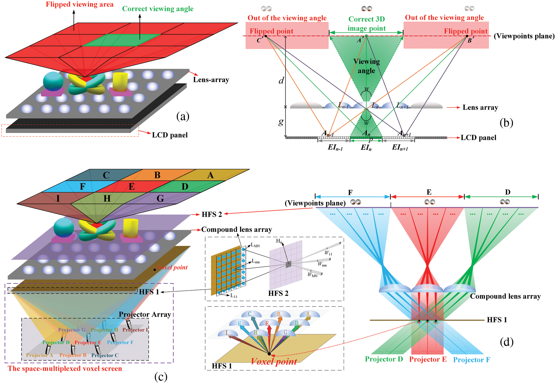
Figure 1: (a) The structure of the InIm display system. (b) The flipping effect in the InIm display. (c) The structure of the demonstrated InIm display system. (d) The optical path diagram
where p represents the size of the elemental image (EI), and g represents the distance between the lens array and LCD panel. However, due to traditional display backlights being mostly scattered light, the light rays carrying the pixels information inevitably enter different lenses, to leading to flipped images. As shown in Fig. 1b, the light rays emitting from An−1, An and An+1 are refracted by the different lenses, and the flipped points B′ and C′ are reconstructed beyond the viewing angle, which have the incorrect direction information compared with A′. This phenomenon is known as flipping effect [28]. Because of the flipping effect, the reconstructed 3D scene with improper parallax relationship appears beyond the valid viewing angle, which limits the viewing area and results in severe discomfort for the observers.
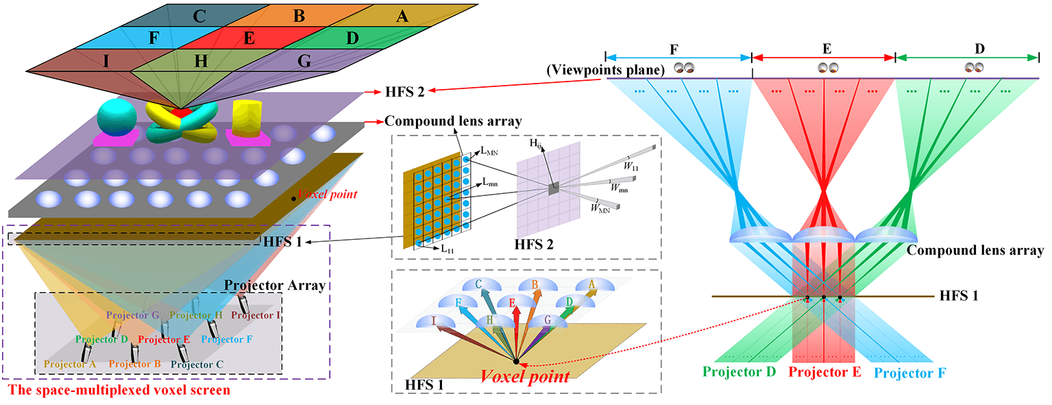
According to the above analysis, the reason for inducing the flipping effect is that the information of the same viewpoint is refracted and imaged by adjacent lenses. Therefore, a novel InIm display system composed of space-multiplexed voxel screen and compound lens array is demonstrated, as shown in Fig. 1c. Similar to traditional InIm display, the proposed InIm display system also uses the lens array to achieve viewpoints imaging to meet the demand for full-parallax display. Different from the conventional InIm display, for the proposed InIm display system, on the one hand, the space-multiplexed voxel screen instead of the traditional LCD panel is introduced to significantly improve the capacity of spatial information. On the other hand, the high spatial resolution 3D image is observed because the gap of compound lens array is eliminated by the holographic functional screen (HFS).
The HFS plays a vital role in recomposing the light rays, which is based on holographic printing technology to expose sensitive materials [34,35]. The required spatial directivity is realized through an orientated speckle pattern by diffraction [36]. When the laser is illuminating a diffusion plate of size a0 ×b0, the speckle pattern is exposed on the photoresist plate behind the diffusion plate, which is recorded at a distance z0. By the ultraviolet curing and splicing method, the repeated speckle patterns consist the HFS. When the speckle pattern is illuminated by a light wave, it diffuses and limits the light in a solid diffused angle ωhorizontal = a0/z0 and ωvertical = b0/z0. By controlling the speckle pattern of the HFS, the exact diffused angle can be achieved. The fully random speckle structure is wavelength-independent and without chromatic aberration, which guarantees high transmission efficiency [23]. Here, two holographic function screens with different parameters are optically designed for the proposed InIm display. Among them, the HFS 1 receives the pixel information loaded from the projector array and forms a series of dense voxel points on the surface. As the length of EI is very small for a projecting system, the light rays passing through the EI on the HFS 1 from a projector can be seen as parallel beams. The number of light rays emitted from voxel pixels is equal to the number of projectors, and the light rays propagating in different directions pass through different compound lenses for imaging, respectively. Therefore, the flipping effect is eliminated by accurately controlling the refraction of light beams with different viewpoints information. The HFS 2 combined compound lens array can not only modulate the light field distribution but also eliminate the gap of the lens. To prevent the flipping effect and ensure high quality, the diffusion angle of each HFS should satisfy Eq. (2).
where the pitch represents the distance of the adjacent compound lenses, and the d represents the distance between the compound lens array and the HFS 2. The configuration of the demonstrated tabletop InIm display system is shown in Fig. 1c and the corresponding optical path diagram is shown in Fig. 1d. Nine projectors are utilized to provide the coded 3D contents, each projector provides the EIA of 70 × 70 viewpoint perspectives in the viewing angle of 32° × 32° through InIm display system. By splicing and combining, the high-quality 3D display image with a 96° × 96° viewing angle is perceived.
2.2 Coding Method for InIm Pickup and Reconstruction
The synthetic encoding mapping method based on backward ray-tracing technology is introduced to render EIAs efficiently and accurately. For simplicity, this method with off-axis pickup is also described by using three projectors in a two-dimensional case. The whole process is divided into two parts. Firstly, the parallax images (PIs) are captured by the virtual camera array (CA) with the off-axis pickup, as shown in Fig. 2a. Then, to guarantee the reconstructed 3D image with correct perception and occlusion in the viewing area, the pixels of different PIs are mapped to the different EIAs based on the geometric relationship to achieve accurate pixel mapping, as shown in Fig. 2b. According to the pickup process, the interval of the adjacent cameras and the viewing angle of the camera in CA are represented by
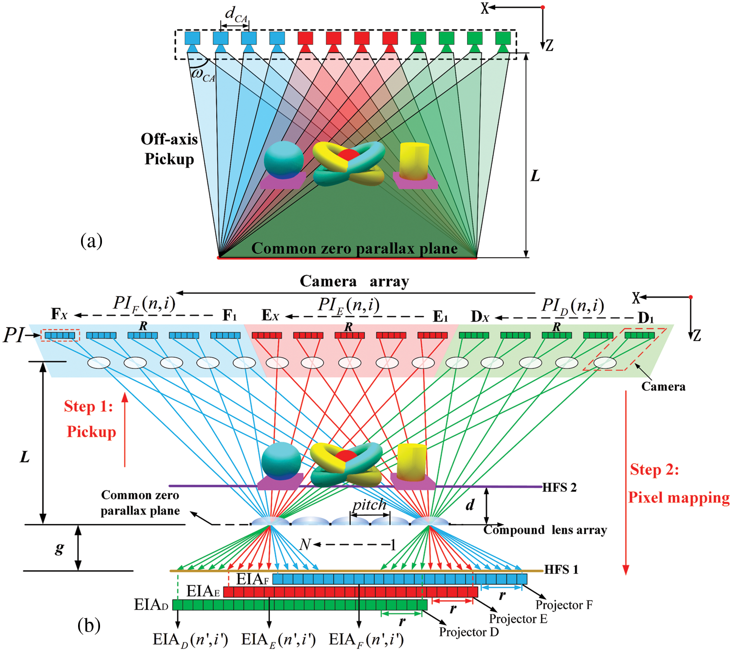
Figure 2: The proposed InIm display based on pickup and code mapping. (a) The pickup process. (b) The reconstruction process
where N and pitch are the number and the length of the lens array in demonstrated InIm display, respectively. L represents the distance between camera array and the compound lens array, and r represents the resolution of each EI covered by the different lens, which is equal to the X ( the number of cameras in each viewing area).
As shown in Fig. 2b, the PIs are captured by camera array, and the precise mapping relationship is described. According to the geometrical relationship, the resolution R of each elemental image in captured image array is the same as the number of the compound lens N of lens array, and the resolution r of each elemental image in EIA is the same as the number of cameras X in each viewing area. The ith row pixel of the nth column elemental image in PI is expressed as PIx(n,i). The light ray emitted from this pixel intersects at the i′th column with that from the pixel of the n′th column elemental image in EIA, which can be expressed as EIAx(n′,i′). Thus, the mathematical description of mapping relationships can be presented in Eq. (4).
with
where n′ represents the value range from 1 to N, i′ represents the value range from 1 to r, and x is within the range from A to I, respectively. According to the proposed coding mapping method, all pixels in PIs are accurately mapped to EIAs.
2.3 Joint Optimization Mechanism of Holographic Functional Screen and the Compound Lens Array
Light through the compound lens array from the HFS 1 illuminates every point on the HFS 2, which is shown in Fig. 3. The HFS 2 processes the necessary optical transformation to re-modulate the distribution of the light rays in a specifically arranged geometry. The integral result of the output re-distribution spatial angle
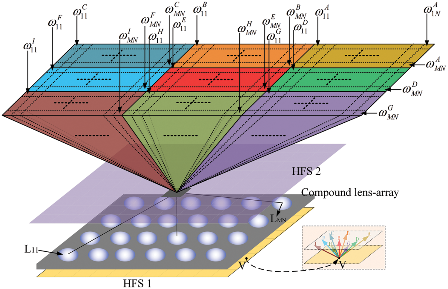
Figure 3: The principle of light field modulation distribution of HFS 2
where the number of the compound lens array is N × M. By controlling the speckle pattern of the HFS, the angular distributions of the light rays with the diffused angles
Due to the large viewing angle, the imaging distortion caused by the lens aberrations cannot be ignored. The lens aberrations decrease the convergence accuracy of the modulated light rays, which will severely deteriorate the 3D display effect. Thus, to further improve image quality, the compound lens consisting of three aspheric surfaces is designed to suppress the aberrations. The aspheric model adopts the base of curvature and the conic constant, which can be deduced in Eq. (7).
where c represents the vertex curvature, r represents the radial coordinate, k represents the conic constant and
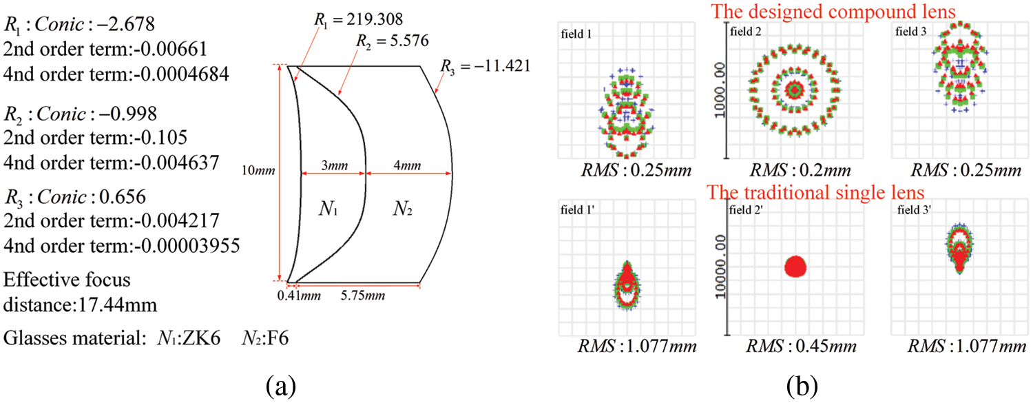
Figure 4: (a) The optimized structure and parameters for the compound lens. (b) Comparison of spot diagrams for the designed compound lens and the single lens
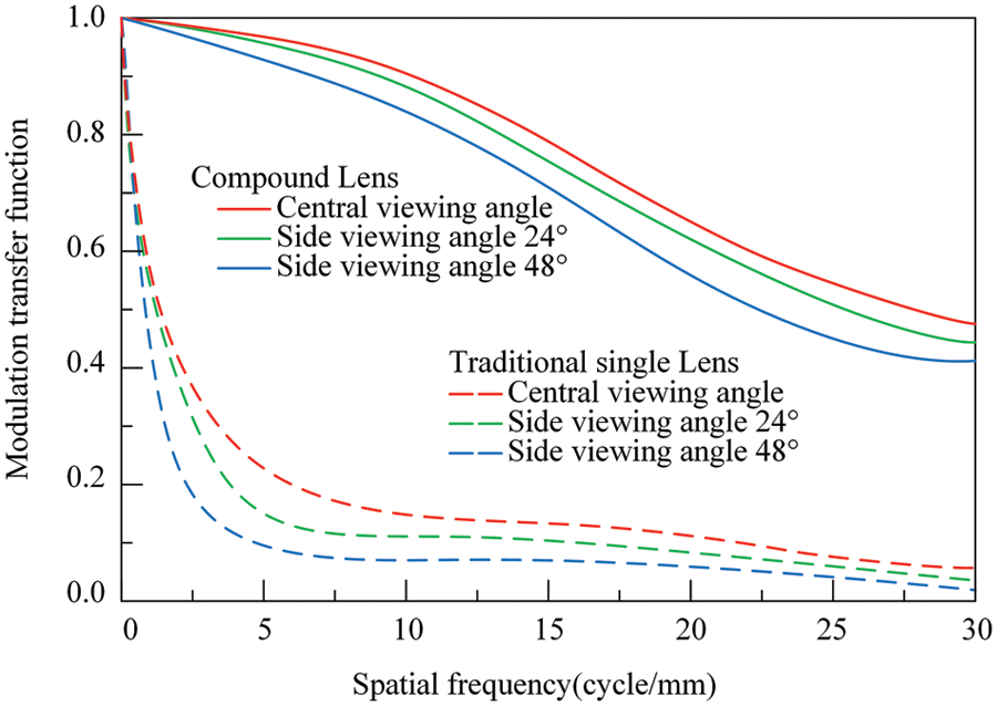
Figure 5: Comparison of the modulation transfer function for the optimized compound lens and the traditional single lens
3 Simulation Analysis and Contrast Experiment
The demonstrated tabletop InIm display based on HFS and compound lens array provides observers with large viewing angle above the table. When elemental images are observed through the single lens array, serious distortion is perceived by the observer’s eye. Moreover, the spacing between the lenses can seriously affect the quality of the reconstructed 3D image and the continuity of the viewing, resulting in a deteriorating visual experience. At a given distance, the imaging distortion
with
where
To rectify the displayed image, the imaging distortion at different distances is compared through simulation experiments. Fig. 6a shows imaging distortion up to more than 30% at the boundary of viewing areas for different display distances. However, the imaging distortion rate declined to less than 9% for the compound lens array with HFS 2 in the whole viewing area under the same parameters, as shown in Fig. 6b. In our demonstrated InIm display system, the HFS 2 combined with the compound lens array not only modulates the light field distribution, but also contributes to the correction of the imaging distortion. In addition, the HFS 2 can eliminate the gap between the compound lens array to obtain the continuous 3D display image.
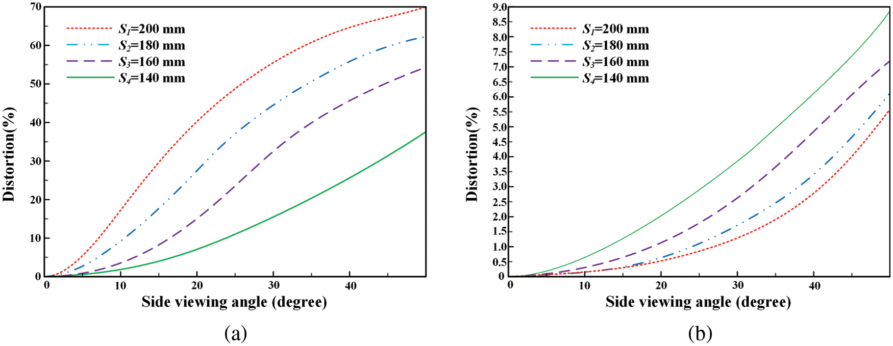
Figure 6: Comparison of imaging distortion at different display distances. (a) The imaging distortion for the conventional single lens array without HFS 2. (b) The imaging distortion for the compound lens array with HFS 2
In the case of the other parameters, to assess the image quality of the reconstructed 3D display image, a simulation method is employed to obtain different viewpoint images for two kinds of lens array. In fact, the displayed image seen by the human eye is formed by stitching a series of pixels in each lens unit. Therefore, the image results are calculated by simulating the actual viewing patterns of the human eye. Therein, the structural similarity index measure (SSIM) is introduced to evaluate the imaging quality. Due to the lens being rotationally symmetric, the central viewpoints of each imaging area corresponding to the three projectors were selected for analysis. As shown in Fig. 7, the SSIM value of the InIm with compound lens array is visibly higher than that with the single lens array, which demonstrates that the InIm display with the compound lens array has higher similarity.
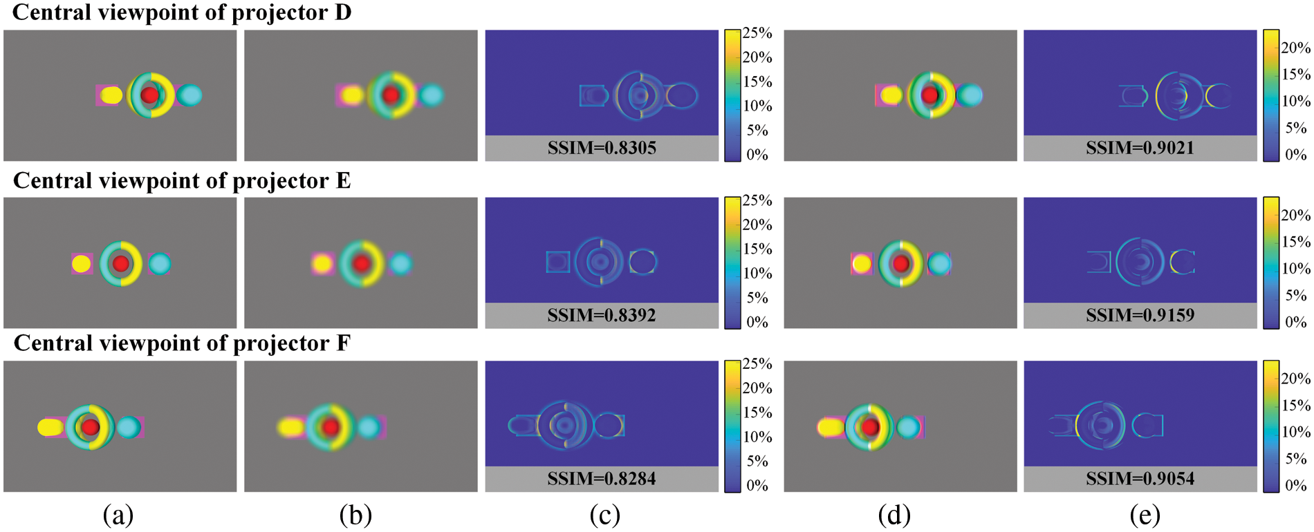
Figure 7: Simulation of SSIM for different central viewpoints from different projectors of the 3D objects. (a) Viewpoints captured from different angles. (b) Simulation results of the conventional InIm display. (c) SSIM of the conventional InIm display system. (d) Simulation results of the proposed InIm display. (e) SSIM of the proposed InIm display with compound lens array
Fig. 8 shows the comparison of the traditional InIm display and the proposed InIm display. As shown in Fig. 8a, severe distortion exists in the 3D image reconstructed by the traditional InIm display, which leads to the deterioration of visual effects. However, by introducing the compound lens array and HFS 2, the imaging distortion is corrected in the whole viewing angle and the quality of reconstructed 3D image is significantly improved, as shown in Fig. 8b. In addition, under the same conditions of other parameters, compared experiments are carried out for the reconstructed 3D display based on different lens array. As shown in Fig. 9, the conventional InIm display system based on single lens array has blurred display images because of the aberration, while the proposed InIm display system based on compound lens array can greatly improve the image quality by optimizing the aberration.
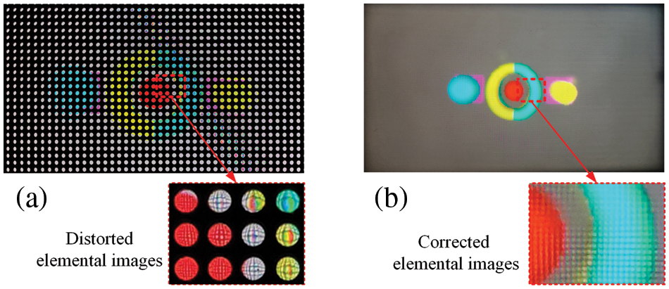
Figure 8: (a) The observed discontinuous 3D image for the conventional single lens array without HFS 2. (b) The observed clear 3D image with compound lens array and HFS 2
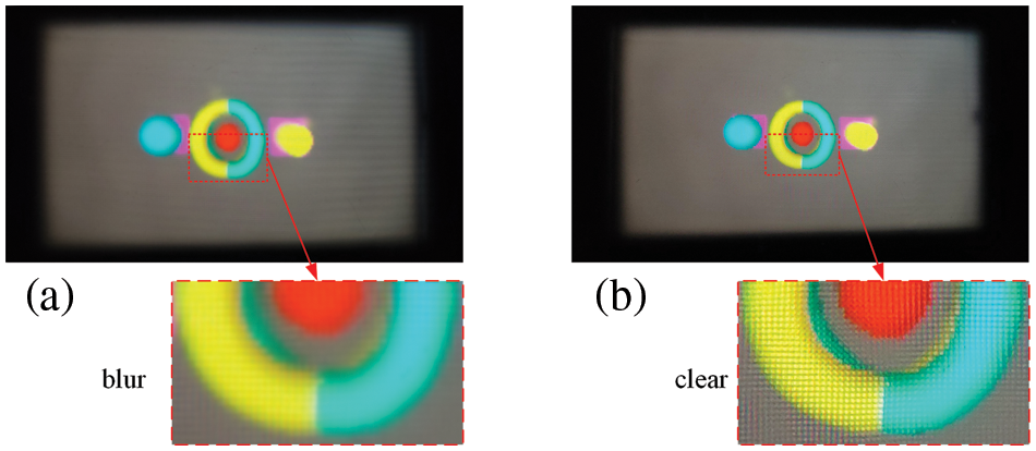
Figure 9: (a) The observed blurry 3D image for the conventional single lens array with HFS 2. (b) The observed clear 3D image for the compound lens array with HFS 2
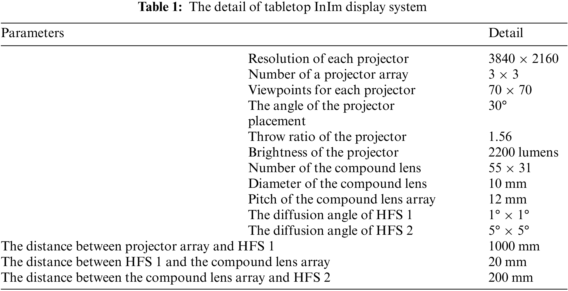
According to the demonstrated InIm display system, the EIAs are loaded and projected on the HFS 1 by the corresponding projectors, and light rays emitted from the HFS 1 are redistributed by the HFS 2 and the compound lens array. In order to minimize the aliasing between the constructed viewpoint perspectives, the HFS 1 with 1° is specifically designed, which can ensure precise beamlet imaging. Due to the gaps between the adjacent compound lens array being noticeable, the HFS 2 with the diffusing angle of 5° is accepted. The projector array consisting of 9 projectors is used to provide the content of the coded image, where the resolution of each projector is 3840 × 2160 (see Fig. 10). To reconstruct the natural 3D perception, the largest number of viewpoints are necessary to realize the high quality of full-parallax 3D image with smooth motion parallax in the whole viewing angle. To verify the effectiveness of the proposed InIm display system, the specific parameters of tabletop InIm display are listed in Table 1. The 3D display image with different shapes of objects is accurately reconstructed by the proposed system, which has correct geometric occlusion and stereo vision.
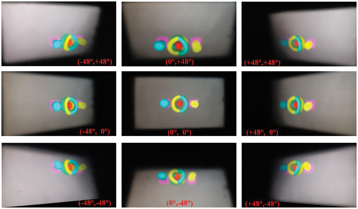
Figure 10: 3D imaging display result captured with different angles
The enhanced viewing angle InIm display system without the flipping effect has important application potential in various fields, especially in medical diagnosis and biological education. Fig. 11 shows the display images captured from different angles. Figs. 11a and 11b show the reconstructed 3D display images of the human lung and human heart and sternum, respectively. It is experimentally verified that the reconstructed high-quality 3D display image with a clear depth of 20 cm and correct spatial occlusion relation can be observed at the 96° × 96° viewing angle.
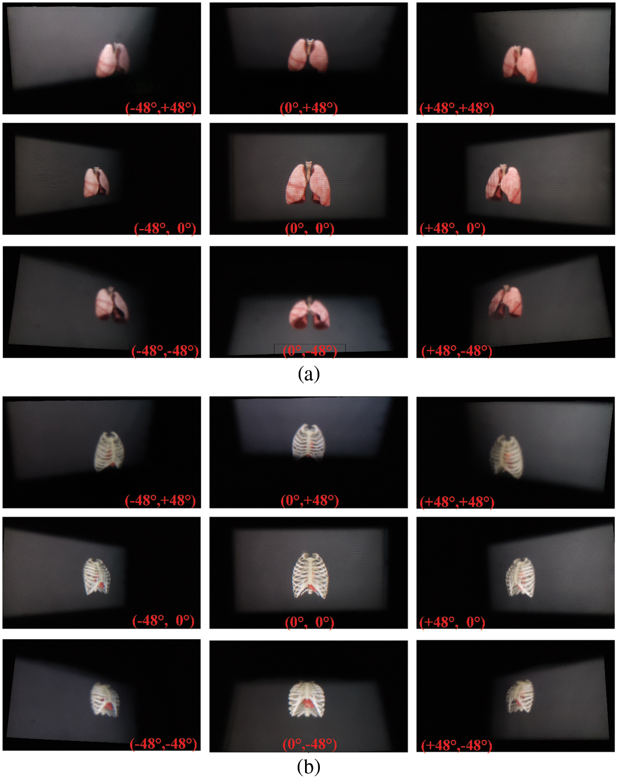
Figure 11: The image captured from different angles. (a) The 3D display images of human lung. (b) The 3D display images of human heart and sternum
The tabletop InIm display technology is generally difficult to implement the high-quality 3D imaging display with high spatial bandwidth product and large viewing angle. Here, a novel flipping-free tabletop InIm display with enhanced viewing angle based on compound lens array and space-multiplexed voxel screen is demonstrated, and two holographic functional screens with different parameters are optically designed and fabricated. The space-multiplexed voxel screen consisting of a projector array and HFS 1 is presented to form a series of voxel points, which emit light rays in different directions and intensities only passing through the corresponding lens unit. To greatly promote the imaging quality within the viewing area, the aspherical structure of the compound lens is optimized to balance the aberrations, and cooperates with HFS 2 to modulate the light field spatial distribution. In the experiment, the reconstructed high-performance floating 3D display images can be observed with acceptable resolution and the right geometric occlusion at a 96° × 96° viewing angle. With the increasing development of science and technology and the growing demand for people’s materialization, the combination of InIm display technology and tabletop display is an urgent need in the information age. The novel tabletop InIm true 3D display will shine in the important fields of medical diagnosis, military simulation and education training in the future.
Acknowledgement: We thank the 2022 IEEE 8th International Conference on Virtual Reality (ICVR 2022) for recommending our paper, and thank Professor Xinzhu Sang’s Group at Beijing University of Posts and Telecommunications for the 3D modeling data of human organs and the off-axis virtual camera software.
Funding Statement: The Basic Research Fund of Central-Level Nonprofit Scientific Research Institutes (No. TKS20220304). The Key Research and Development Projects of Guangxi Science and Technology Department (No. 2021AB05087).
Conflicts of Interest: The authors declare no conflicts of interest. This work is original and has not been published elsewhere.
References
1. Geng, J. (2013). Three-dimensional display technologies. Advances in Optics and Photonics, 5(4), 456–535. https://doi.org/10.1364/AOP.5.000456 [Google Scholar] [PubMed] [CrossRef]
2. Li, X. P., Ren, H. R., Chen, X., Liu, J., Li, Q. et al. (2015). Athermally photoreduced graphene oxides for three-dimensional holographic images. Nature Communications, 6(1), 6984. https://doi.org/10.1038/ncomms7984 [Google Scholar] [PubMed] [CrossRef]
3. Yu, H., Lee, K., Park, J., Park, Y. K. (2017). Ultrahigh-definition dynamic 3D holographic display by active control of volume speckle fields. Nature Photonics, 11(3), 186–192. https://doi.org/10.1038/nphoton.2016.272 [Google Scholar] [CrossRef]
4. Wakunami, K., Hsieh, P. Y., Oi, R., Senoh, T., Sasaki, H. et al. (2016). Projection-type see-through holographic three-dimensional display. Nature Communications, 7(1), 12954. https://doi.org/10.1038/ncomms12954 [Google Scholar] [PubMed] [CrossRef]
5. Liu, X., Li, H. F. (2014). The progress of light field 3-D displays. Information Display, 30(6), 6–14. https://doi.org/10.1002/j.2637-496X.2014.tb00760.x [Google Scholar] [CrossRef]
6. Jang, C., Lee, C. K., Jeong, J., Li, G., Lee, S. et al. (2016). Recent progress in see-through three-dimensional displays using holographic optical elements [Invited]. Applied Optics, 55(3), A71–A85. https://doi.org/10.1364/AO.55.000A71 [Google Scholar] [PubMed] [CrossRef]
7. Yamaguchi, M. (2016). Light-field and holographic three-dimensional displays [Invited]. Journal of the Optical Society of America A, 33(12), 2348–2364. https://doi.org/10.1364/JOSAA.33.002348 [Google Scholar] [PubMed] [CrossRef]
8. Smalley, D. E., Nygaard, E., Squire, K., van Wagoner, J., Rasmussen, J. et al. (2018). A photophoretic-trap volumetric display. Nature, 553(7689), 486–490. https://doi.org/10.1038/nature25176 [Google Scholar] [PubMed] [CrossRef]
9. Park, J. C., Lee, K., Park, Y. (2019). Ultrathin wide-angle large-area digital 3D holographic display using a non-periodic photon sieve. Nature Communications, 10, 1304. https://doi.org/10.1038/s41467-019-09126-9 [Google Scholar] [PubMed] [CrossRef]
10. Zhao, Y., Cao, L. C., Zhang, H., Kong, D., Jin, G. (2015). Accurate calculation of computer-generated holograms using angular-spectrum layer-oriented method. Optics Express, 23(20), 25440–25449. https://doi.org/10.1364/OE.23.025440 [Google Scholar] [PubMed] [CrossRef]
11. Favalora, G. E. (2005). Volumetric 3D displays and application infrastructure. Computer, 38(8), 37–44. https://doi.org/10.1109/MC.2005.276 [Google Scholar] [CrossRef]
12. Lippmann, G. (1908). Épreuves réversibles: Photographies integrals. Comptes Rendus de l’Académie des Sciences, 146(3), 446–451. https://doi.org/10.1002/ardp.18240070312 [Google Scholar] [CrossRef]
13. Kim, Y., Hong, H., Lee, B. (2010). Recent researches based on integral imaging display method. 3D Research, 1(1), 17–27. https://doi.org/10.1007/3DRes.01(2010)2 [Google Scholar] [CrossRef]
14. Hong, J., Kim, Y., Choi, H. J., Hahn, J., Park, J. H. et al. (2011). Three-dimensional display technologies of recent interest: Principles, status, and issues. Applied Optics, 50(34), H87–H115. https://doi.org/10.1364/AO.50.000H87 [Google Scholar] [PubMed] [CrossRef]
15. Xiao, X., Bahram, J., Manuel, M. C., Adrian, S. (2013). Advances in three-dimensional integral imaging: Sensing, display, and applications [Invited]. Applied Optics, 52(4), 546–560. https://doi.org/10.1364/AO.52.000546 [Google Scholar] [PubMed] [CrossRef]
16. Manuel, M. C., Bahram, J. (2018). Fundamentals of 3D imaging and displays: A tutorial on integral imaging, light-field, and plenoptic systems. Advances in Optics and Photonics, 10(3), 51–566. https://doi.org/10.1364/aop.10.000512 [Google Scholar] [CrossRef]
17. Deng, H., Wang, Q. H., Li, L., Li, D. H. (2011). An integral-imaging three-dimensional display with wide viewing angle. Journal of the Society for Information Display, 19(10), 679–683. https://doi.org/10.1889/JSID19.10.679 [Google Scholar] [CrossRef]
18. Deng, H., Wang, Q. H., Wu, F., Luo, C. G., Liu, Y. (2015). Cross-talk-free integral imaging three-dimensional display based on a pyramid pinhole array. Photonics Research, 3(4), 173–176. https://doi.org/10.1364/PRJ.3.000173 [Google Scholar] [CrossRef]
19. Liao, H., Inomata, T., Sakuma, I., Dohi, T. (2010). 3-D augmented reality for MRI-guided surgery using integral videography autostereoscopic image overlay. IEEE Transactions on Biomedical Engineering, 57(6), 1476–1486. https://doi.org/10.1109/tbme.2010.2040278 [Google Scholar] [PubMed] [CrossRef]
20. Liang, Y. Z., Fang, B., Wang, Y., Wu, L., Chen, P. (2011). Design of an interactive 3D medical visualization system. 2011 International Conference on Wavelet Analysis and Pattern Recognition, pp. 60–64. Guilin, China. https://doi.org/10.1109/ICWAPR.2011.6014485 [Google Scholar] [CrossRef]
21. Liao, H., Fan, Z., Zhang, X. (2017). High spatiotemporal resolution biomedical imaging and visualization. Asia Communications and Photonics Conference, Guangzhou, China. https://doi.org/10.1364/ACPC.2017.M1I.1 [Google Scholar] [CrossRef]
22. Holler, M., Guizar, M., Tsai, E. H. R., Dinapoli, R., Müller, E. et al. (2017). High-resolution non-destructive three-dimensional imaging of integrated circuits. Nature, 543(7645), 402–406. https://doi.org/10.1038/nature21698 [Google Scholar] [PubMed] [CrossRef]
23. Sang, X., Gao, X., Yu, X., Xing, S., Li, Y. et al. (2018). Interactive floating full-parallax digital three-dimensional light-field display based on wavefront recomposing. Optics Express, 26(7), 8883–8889. https://doi.org/10.1364/OE.26.008883 [Google Scholar] [PubMed] [CrossRef]
24. Xiong, Z. L., Wang, Q. H., Li, S. L., Deng, H., Ji, C. C. (2014). Partially-overlapped viewing zone based integral imaging system with super wide viewing angle. Optics Express, 22(19), 22268–22277. https://doi.org/10.1364/OE.22.022268 [Google Scholar] [PubMed] [CrossRef]
25. Park, G., Jung, J. H., Hong, K., Kim, Y., Kim, Y. H. et al. (2009). Multi-viewer tracking integral imaging system and its viewing zone analysis. Optics Express, 17(20), 17895–17908. https://doi.org/10.1364/OE.17.017895 [Google Scholar] [PubMed] [CrossRef]
26. Kim, J., Park, G., Kim, Y., Min, S. W., Lee, B. (2009). Elimination of image discontinuity in integral floating display by using adaptive image mapping. Applied Optics, 48(34), H176–H185. https://doi.org/10.1364/AO.48.00H176 [Google Scholar] [PubMed] [CrossRef]
27. Lee, B., Jung, S., Park, J. H. (2002). Viewing-angle-enhanced integral imaging by lens switching. Optics Letters, 27(10), 818–820. https://doi.org/10.1364/OL.27.000818 [Google Scholar] [PubMed] [CrossRef]
28. Zhang, W., Sang, X., Gao, X., Yu, X., Yu, C. (2019). A flipping-free 3D integral imaging display using a twice-imaging lens array. Optics Express, 27(22), 32810–32822. https://doi.org/10.1364/OE.27.032810 [Google Scholar] [PubMed] [CrossRef]
29. Tolosa, A., Martinez, R., Navarro, H., Saavedra, G., Martínez-Corral, M. et al. (2014). Enhanced field-of-view integral imaging display using multi-Köhler illumination. Optics Express, 22(26), 31853–31863. https://doi.org/10.1364/OE.22.031853 [Google Scholar] [PubMed] [CrossRef]
30. Yang, L., Sang, X., Yu, X., Yan, B., Wang, K. et al. (2019). Viewing-angle and viewing-resolution enhanced integral imaging based on time-multiplexed lens stitching. Optics Express, 27(11), 15679–15692. https://doi.org/10.1364/OE.27.015679 [Google Scholar] [PubMed] [CrossRef]
31. Xing, Y., Ren, H., Li, S., Xia, Y., Wang, Q. H. (2021). Integral imaging tabletop 3D display system. Proceedings of SPIE 11708, Advances in Display Technologies XI, 117080C. https://doi.org/10.1117/12.2577603 [Google Scholar] [CrossRef]
32. Kim, Y., Park, J. H., Choi, H., Jung, S., Min, S. W. et al. (2004). Viewing-angle-enhanced integral imaging system using a curved lens array. Optics Express, 12(3), 421–429. https://doi.org/10.1364/OPEX.12.000421 [Google Scholar] [PubMed] [CrossRef]
33. Martinez, R., Navarro, H., Saavedra, G., Javidi, B., Martínez-Corral, M. (2007). Enhanced viewing-angle integral imaging by multiple-axis telecentric relay system. Optics Express, 15(24), 16255–16260. https://doi.org/10.1364/OE.15.016255 [Google Scholar] [PubMed] [CrossRef]
34. Yu, C., Yuan, J., Fan, F. C., Jiang, C. C., Choi, S. et al. (2010). The modulation function and realizing method of holographic functional screen. Optics Express, 18(26), 27820–27826. https://doi.org/10.1364/OE.18.027820 [Google Scholar] [PubMed] [CrossRef]
35. Sang, X., Fan, C. F., Choi, S., Jiang, C. C., Yu, C. et al. (2011). Three-dimensional display based on the holographic functional screen. Optical Engineering, 50(9), 91303. https://doi.org/10.1117/1.3596176 [Google Scholar] [CrossRef]
36. Sang, X., Fan, C. F., Choi, S., Dou, W., Yu, C. et al. (2009). Demonstration of a large-size real-time full-color three-dimensional display. Optics Letters, 34(24), 3803–3805. https://doi.org/10.1364/OL.34.003803 [Google Scholar] [PubMed] [CrossRef]
Cite This Article
 Copyright © 2023 The Author(s). Published by Tech Science Press.
This work is licensed under a Creative Commons Attribution 4.0 International License , which permits unrestricted use, distribution, and reproduction in any medium, provided the original work is properly cited.
 Downloads
 Citation Tools