
 Submit a Paper
 Propose a Special lssue
 Open Access
ARTICLE

Geometrically Nonlinear Flutter Analysis Based on CFD/CSD Methods and Wind Tunnel Experimental Verification
Institute of High Speed Aerodynamics, China Aerodynamics Research and Development Center, Mianyang, 621000, China
* Corresponding Author: Hongya Xia. Email:
(This article belongs to the Special Issue: Vibration Control and Utilization)
Computer Modeling in Engineering & Sciences 2023, 136(2), 1743-1758. https://doi.org/10.32604/cmes.2023.025528
Received 18 July 2022; Accepted 09 October 2022; Issue published 06 February 2023
 View Full Text
 Download PDF
Abstract
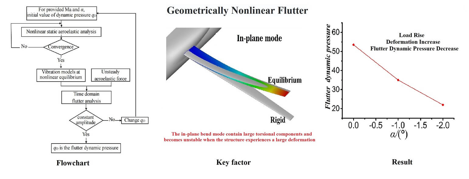
This study presents a high-speed geometrically nonlinear flutter analysis calculation method based on the high-precision computational fluid dynamics/computational structural dynamics methods. In the proposed method, the aerodynamic simulation was conducted based on computational fluid dynamics, and the structural model was established using the nonlinear finite element model and tangential stiffness matrix. First, the equilibrium position was obtained using the nonlinear static aeroelastic iteration. Second, the structural modal under a steady aerodynamic load was extracted. Finally, the generalized displacement time curve was obtained by coupling the unsteady aerodynamics and linearized structure motion equations. Moreover, if the flutter is not at a critical state, the incoming flow dynamic pressure needs to be changed, and the above steps must be repeated until the vibration amplitude are equal. Furthermore, the high-speed geometrically nonlinear flutter of the wing-body assembly model with a high-aspect ratio was investigated, and the correctness of the method was verified using high-speed wind tunnel experiments. The results showed that the geometric nonlinearity of the large deformation of the wing caused in-plane bending to become a key factor in flutter characteristics and significantly decreased the dynamic pressure and frequency of the nonlinear flutter compared to those of the linear flutter.Graphic Abstract
Keywords
A high-altitude long-endurance aircraft can be used as a transfer platform for scientific research and remote communication because of its unique flight ability, which has resulted in its wide development [1,2]. In recent years, high-altitude long-endurance unmanned aerial vehicles have primarily adopted high-aspect-ratio wings, low structural densities, and large flexibility to obtain higher lifts [3,4]. However, the large deformation of airfoil under aerodynamic loads makes the conventional aeroelastic linear analysis method based on the small structural deformation inappropriate. Therefore, the geometrical nonlinear effect caused by the large structural deformation must be considered in new methods.
The strip theory and panel method are used to solve geometrically nonlinear aeroelastic problems by coupling structural nonlinear methods owing to the high computational efficiency [5,6]. Patil et al. [7] investigated the influence of geometric nonlinearity on the flutter using the nonlinear beam theory and panel method, and concluded that the large deformation effect significantly decreased the flutter speed and affected the flight envelope. Shams et al. [8] used the Wagner function to transform Theodorsen’s aerodynamic force from the frequency domain into the time domain to couple the second-order beam theory and Hodges–Dowell equations; thus, they obtained the stability problem of the high-aspect-ratio wing using the Galerkin method. Yang et al. [9] analyzed the static aeroelasticity of flexible aircraft using the three-dimensional curved vortex lattice method coupled with the nonlinear structural finite element method, and concluded that the aircraft design should avoid excessive deformation on the aerodynamic performance. As for the efficiency of the nonlinear flutter calculations, Xie et al. [10,11] linearized the structural motion equation at the nonlinear equilibrium position, and analyzed the influence of the structural geometric nonlinearity on the natural vibration and flutter response of high-aspect-ratio wings at low speeds. However, that method could not consider aerodynamic nonlinear factors, such as the high attack angles and transonic flows. Additionally, Arena et al. [12–14] used the stall strip theory and nonlinear beam equation to investigate the coupling of wing dynamic response and flight dynamics. Kim et al. [15] adopted the transonic small perturbation potential and large deformation beam theories to analyze the aeroelasticity of high-aspect-ratio wings. Tang et al. [16] investigated the ONERA nonlinear aerodynamic model to couple the Hodges–Dowell equations, and concluded that the geometric nonlinearity and aerodynamic stall affect the limit cycle motion of the high-aspect-ratio wing after instability. A comprehensive study on the aerodynamic nonlinearity of flexible wings with a high-aspect ratio was conducted in [17].
The high-precision computational fluid dynamics (CFD)/computational structural dynamics (CSD) coupling methods are typically used to analyze nonlinear aeroelastic problems owing to the improved performance of existing computers. Smith et al. [18] used the Euler equation solver and nonlinear beam theory to calculate the large deformation of wings with a high-aspect ratio under incompressible conditions. The results indicated that the panel method overestimated the static deformation and lift compared with the conventional panel method. Garcia [19] used CFD and the structural nonlinear coupling method to investigate the static deformation of a swept wing with a high-aspect ratio under transonic conditions. It was found that the vertical bending displacement increased the torque, which increased the effect of drag on the torque. The outward wash (bow twist) of the swept wing in the nonlinear structure was less than that of the linear structure; thus, the local attack angle was lifted and dragged higher than that of the linear structure. Nie et al. [20] concluded similar results using a structured CFD program coupled with a nonlinear finite element method to investigate the transonic large deformation of swept wings. Bendiksen [21] solved the transonic limit cycle flutter of swept wings with a high aspect ratio using the nonlinear plate theory and Euler equation, and concluded that the structural outward wash effect was the cause of limited cycle vibrations. Moreover, the linear structure method overestimates the critical speed of the limit cycle by approximately three times. The time-domain method based on CFD is used to calculate the flutter in linear structures. Bartels et al. [22] calculated the unsteady aerodynamic force and the response of the linear wing-body mode using the unstructured Navier–Stokes program FUN3D under no preload conditions. However, the flutter velocity calculated using that method cannot consider the influence of geometric nonlinearities.
Additionally, the geometrically nonlinear CFD/CSD coupling is primarily used to solve static aeroelastic problems. Geometrically nonlinear flutter calculations and wind tunnel experiments are focused on low-speed aspects. However, few studies have been conducted on the simulation and wind tunnel verification experiments of high-speed geometrically nonlinear flutter characteristics. The flutter velocity of a large deformation is associated with the static deformation of the structure, which requires the static equilibrium position to be correctly calculated prior to the flutter analysis. In addition, the accurate prediction of structural static deformation and flutter boundary depends on the high accuracy simulation of aerodynamic forces. The high-precision CFD method must be used for calculations because the linearized potential flow theory cannot reflect viscous effects, surge, zero attack angle aerodynamic forces, aerodynamic disturbances between components, and other factors. Therefore, this study focused on the high-speed nonlinear flutter analysis of the wing-body assembly based on the coupled CFD/CSD nonlinear flutter calculation method, and the reliability of the calculation method in the high-speed range was verified using wind tunnel experiments.
2 Numerical Calculations of Geometrically Nonlinear Flutter Based on CFD/CSD
In this study, a computational method for the large deformation effect of flutter is introduced based on CFD/CSD. The flowchart of the nonlinear flutter analysis is shown in Fig. 1. First, the nonlinear static equilibrium state is predicted, and the equilibrium state of the aerodynamic shape and the natural vibration mode of the structure are solved. Subsequently, the structure is assumed to make micro-amplitude vibrations near its nonlinear static equilibrium state. Finally, the linear structural motion equation of the equilibrium state and the time history of the generalized displacement are solved, respectively. Moreover, the variable pressure is changed and the above steps are repeated if the flutter is not at the critical state. Because both the geometric and aerodynamic nonlinearities are considered, the method can be applied to the large deformation flutter calculations.

Figure 1: Flowchart of the nonlinear flutter analysis
The aerodynamic force is obtained by solving the Navier–Stocks equation, and the time-dependent three-dimensional conservative compressible Reynolds average Navier–Stokes (RANS) equation is used as the governing equation. In the curvilinear coordinate system (ξ, η, ζ), its dimensionless form is expressed as
where t and Q are the time and conservation variables, respectively. In addition, F, G, and H are inviscid vector fluxes; and Fv, Gv, and Hv are viscous vector fluxes.
The Spalart–Allmaras model expressed in Eq. (1) is selected for turbulence simulations and the implicit double time step method is used to time advance. The convection and viscous terms are discretized using the upwind-biased ROE format and Jameson’s central difference scheme, respectively. Additionally, the multi-grid technique is applied to accelerate the convergence of CFD calculations.
When the geometric nonlinearity deforms, the stress-strain relationship and strain-displacement are linear and nonlinear, respectively. The structural stiffness characteristics during the analysis need to be described using the tangent stiffness matrix, that is,
where K0 and KL are the small displacement (elastic) and large displacement stiffness matrices, respectively; the former is independent of the unit node displacement, whereas the latter depends on it. In addition, Kσ is the initial stress stiffness matrix. A comprehensive study on the tangent stiffness matrix was presented in [23].
The effect of structural geometric nonlinearity on the aeroelastic properties of high-aspect-ratio wings is reflected as follows. First, the structural stiffness changes with load. Second, the nonlinear deformation of the wing affects the aerodynamic distribution. Considering the structural dynamic characteristics of geometric nonlinearity, the structure slightly vibrates near the equilibrium position of the large static deformation. Consequently, the tangent stiffness matrix can be used to replace the conventional stiffness matrix, and natural frequencies and modes can be used in the vibration theory of linear systems.
2.3 Solution of the Nonlinear Static Equilibrium Position
The equilibrium relationship of geometrically nonlinear hydrostatic aeroelasticity is a balance between the internal (elastic) and external forces, which can be written as
where
To analyze the static aeroelastic deformation of the wing, the RANS equation is first used for aerodynamic modeling. Second, the structural model is established using the nonlinear finite element method with root solid boundary conditions to constrain the structural rigid body degrees of the wing freedom, and the aerodynamic force and nonlinear structural deformation are calculated alternately. Finally, the tangent stiffness matrix is extracted after calculating the aerodynamic force and shape at the static equilibrium position.
2.4 Geometrically Nonlinear Flutter Calculation Method
In this study, the modal method was used to conduct the flutter analysis. First, the geometric nonlinear static aeroelastic iteration method was used to obtain the static equilibrium force and static equilibrium position, respectively. Subsequently, the flutter analyses are performed using the equilibrium position mode. Finally, the occurrence of the flutter is determined by observing the attenuation or divergence of the time history curve in the generalized displacement.
The vibration equation of the structure near the equilibrium position is confirmed by
where
Because x is a small quantity, the elastic force
where K is the tangential stiffness matrix at the equilibrium position. The following equation can be derived using Eq. (3) and substituting Eqs. (5) and (6) into Eq. (4):
Eq. (7) is linearized in terms of the vibration x, and
where x is expressed by the form of modal coordinates x = Φq. In addition, Φ and q are the modal matrix and generalized displacement vector, respectively. Substituting the modal coordinates into Eq. (7) can yield
where M* and K* are the generalized mass and stiffness matrices, respectively; and
2.5 Pneumatic/Structural Data Transfer and Flow Field Mesh Deformation Methods
The analysis of aeroelasticity requires data exchange at the coupling surface of the aerodynamic structure. Indeed, the aerodynamic forces derived from the aerodynamics calculations are applied to the structural nodes. Moreover, displacements of the structural nodes are fed back to the aerodynamics mesh nodes after the structural deformation. To increase the computational efficiency and interpolation accuracy, this study adopts the 3D thin-plate spline interpolation (TPSI) method. The TPSI method was presented in [24–26].
In this study, the radial basis function (RBF) combined with the trans-finite interpolation (TFI) method was used to deform the structured flow field mesh. RBF can be regarded as a 3D extension of the surface spline interpolation method [27]. Its interpolation equation is expressed as follows:
where ri (xi, yi, zi) is the coordinate of the known point with the number n and φ is the basis function near the distance ||r−ri||. In this study, we assumed φ(||r−ri||) = ||r−ri||3 and ψ = b0 + b1x + b2y + b3z. In addition, coefficients of the interpolation formula
After the displacement of points on the edge of each mesh block is obtained based on the RBF method, the point displacements inside the grid block surface can be obtained by interpolation based on the grid block edge TFI method. Similarly, displacement of the internal points of the mesh block can be obtained by interpolation based on the mesh block surface using the TFI method [28].
3.1 Wind Tunnel Experiment Model
As shown in Fig. 2, the experimental model is a wing-body assembly half-mode shape, which is tested in a 2.4-m transonic wind tunnel. The model body and symmetrical wing are rigid with the rectification effect and elastic, respectively. Fig. 3 shows that the length of the exposed wing, root, and tip chord are 1800, 235, and 100 mm, respectively. Its leading and trailing edge swept-back angles are 4.3 and 0°, respectively. In Fig. 4, two main wing beams, ribs, and skin are made of fiber-reinforced composites, glass fiber, and carbon fiber, respectively. The latter two parts are filled with Degussa foam, whose finite element model is shown in Fig. 5. Finally, the ground and vibration stiffnesstests (GVTs) are conducted based on the experimental model. In addition, the modal frequencies of each order are obtained by GVTs. Table 1 lists the analysis results based on the finite element theory. The comparison of the experimental and theoretical results reveals that the coincidence error is less than 2.5%. Consequently, the constructed theoretical finite element model can reflect the structural dynamic properties of the actual model.

Figure 2: A half-mode wing-body assembly

Figure 3: Experimental model diagram

Figure 4: Internal structure diagram of a double-beam elastic wing

Figure 5: Finite element model

The geometrically nonlinear computational model consists with the wind tunnel experiment model, and its CFD calculation surface grid is shown in Fig. 6. The number of spatial grid cells is approximately 2.5 M. Because the fuselage is considerably stiffer than the wing, the fuselage is considered as a rigid body. To simulate the aerodynamic interference of the fuselage on the wing, the aerodynamic shape of the fuselage is simulated in the numerical calculation process. The first fifth order elastic mode of the wing is considered in the flutter calculation, whereas the effect of structural damping is not considered. The calculation conditions are as follows:
i) Mach numbers (Ma) at 0.4, 0.6. and 0.7, respectively;
ii) Dynamic pressures (qD) at 18–65 kPa;
iii) Attack angles (α) at −2, −1, and 0°, respectively.

Figure 6: Initial CFD computational grid
4.1 Results of the Conventional Flutter Calculation Method
When the geometrical nonlinearity of the wing is not considered, the flutter characteristics of the wing near the zero attack angle are the flutter characteristics under the low-load condition. In addition, no geometric or aerodynamic torsion from the root to the tip exists, which is because of the symmetrical airfoil. Therefore, α = 0° and modal parameters are used in the conventional flutter calculation and linearized finite element analysis, respectively.
The typical displacement vibration history and amplitude spectrum, corresponding to the modal space in the generalized coordinate system, are shown in Fig. 7. Under the low-load condition, the Mach number is 0.4, 0.6, or 0.7; flutter dynamic pressure is 61.5, 53.5, or 45.5 kPa; and flutter frequency is 65.6, 47.8, or 46.4 Hz. Furthermore, the flutter is coupled with the conventional wing bending-torsion under the low-load condition.


Figure 7: Computational results of the wing flutter under low-load conditions (Ma = 0.7)
4.2 Results of the Geometrically Nonlinear Flutter Calculation Method
The new equilibrium position of the wing under external load and the modal parameters at the above deformation displacement should be calculated to obtain the flutter characteristics of the wing under geometric nonlinearity. Therefore, the computation of geometrically nonlinear flutter must be completed in two steps. In the first step, the new equilibrium position and corresponding modal parameters under the geometric nonlinear condition are obtained based on the coupled iteration of the constant CFD solver and nonlinear finite element structure solver. In the second step, the obtained model equilibrium position and corresponding modal parameters are substituted into the nonlinear flutter solver.
Table 2 and Fig. 8 demonstrate the equilibrium position of the wing and corresponding modal parameters. It can be seen that the models with attack angles have a large deformation under an external load, such as Ma = 0.7, qD = 40 kPa, α = −1°, where the wing-tip deformation is −361 mm; this deformation reaches 20% of the half-wing span. The wing structural characteristics are changed by the aerodynamic load at the provided attack angle owing to the influence of geometric nonlinearity. Compared with the original equilibrium position, the modal frequency of the wing has changed, among which the largest change is the third-order modal (in-plane modal) frequency. For example, it is decreased by 15.5% and 18.0% at (Ma = 0.7, qD = 40 kPa, α = −1°) and (Ma = 0.7, qD = 20 kPa, α = −2°), respectively. Consequently, the in-plane modal frequency is negatively correlated with the external load and deformation. Additionally, the in-plane bending and torsional modes have obviously torsional and in-plane bending components, respectively.


Figure 8: First five mode shapes at the equilibrium point (Ma = 0.7, α = −1°, qD = 33.3 kPa)
Figs. 9 and 10 show the typical calculated results of geometrically nonlinear flutter, critical flutter pressure, and frequency under different Mach numbers and attack angles. It can be seen that the wing deformation increases with the increase of the attack angle, whereas the flutter dynamic pressure and frequency change adversely. When the Mach number is 0.7, for attack angles of −1 and −2°, the nonlinear flutter dynamic pressure is 33.3 and 19.0 kPa, respectively. In addition, the corresponding nonlinear flutter frequencies are 38.3 and 36.2 Hz, which are close to the corresponding in-plane mode frequencies of 41.7 and 39.41 Hz, respectively. Furthermore, compared with that of the linear flutter at the zero attack angle, the dynamic pressure decreased by 26.4% and 58.3%, and the flutter frequency decreased by 17.9% and 22.0%, respectively. This result is attributed to the geometric nonlinear effect, which makes the in-plane bending mode contain large torsional components, as shown in Fig. 8, and becomes unstable when the structure experiences a large deformation. Thus, the nonlinear stability analysis of an extremely flexible wing reveals that the in-plane bend mode is essential in flutter characteristics.

Figure 9: Numerical simulation of the nonlinear wing flutter (Ma = 0.7, α = −1°)
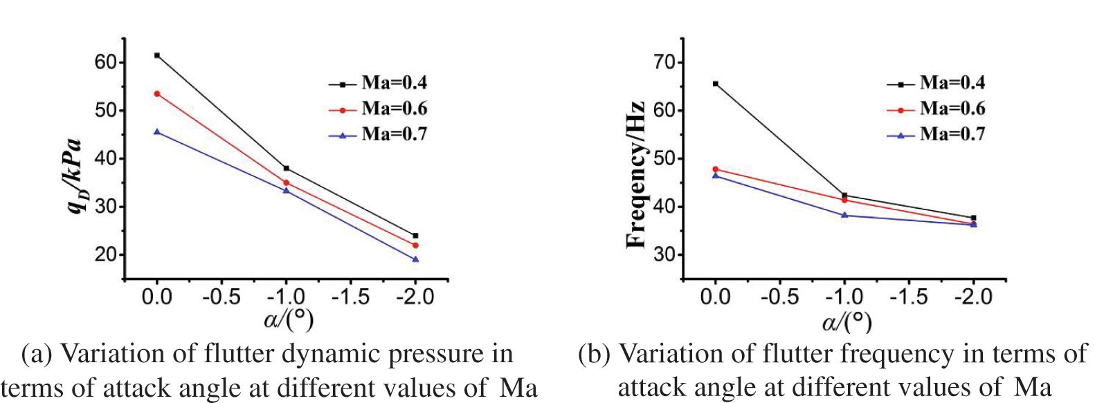
Figure 10: Computational results of flutter
The geometrically nonlinear flutter experiments were conducted in 2.4 m transonic wind tunnel. The Mach number and attack angle were fixed to test with a step variable dynamic pressure. The bending/torsional strains of the wing at different spanwise positions were measured using a resistance strain gauge attached to the inside of the wing, and the vibration signals of the model were recorded in real-time. The selected experimental Mach numbers were 0.4, 0.6, and 0.7, and attack angles were 0 and −1° to obtain the effect of geometric nonlinearity caused by large deformations. Because the experimental dynamic pressure was far from the flutter dynamic pressure at Ma = 0.4 and 0.6, a reliable flutter boundary was not obtained. Therefore, this study presents the experimental results at Ma = 0.7. Figs. 11–14 illustrate the bending moment, torsion, in-plane bending, and vibration response time history of the critical point of flutter at Ma = 0.7 for α = 0°, −1°. The experiments were not carried out at higher speeds (higher Mach numbers) because the model was damaged at Ma = 0.7. In future studies, higher Mach numbers can be used in simulations and experiments.

Figure 11: Typical vibration response time history in the wind tunnel experiments at Ma = 0.7 and α = 0°
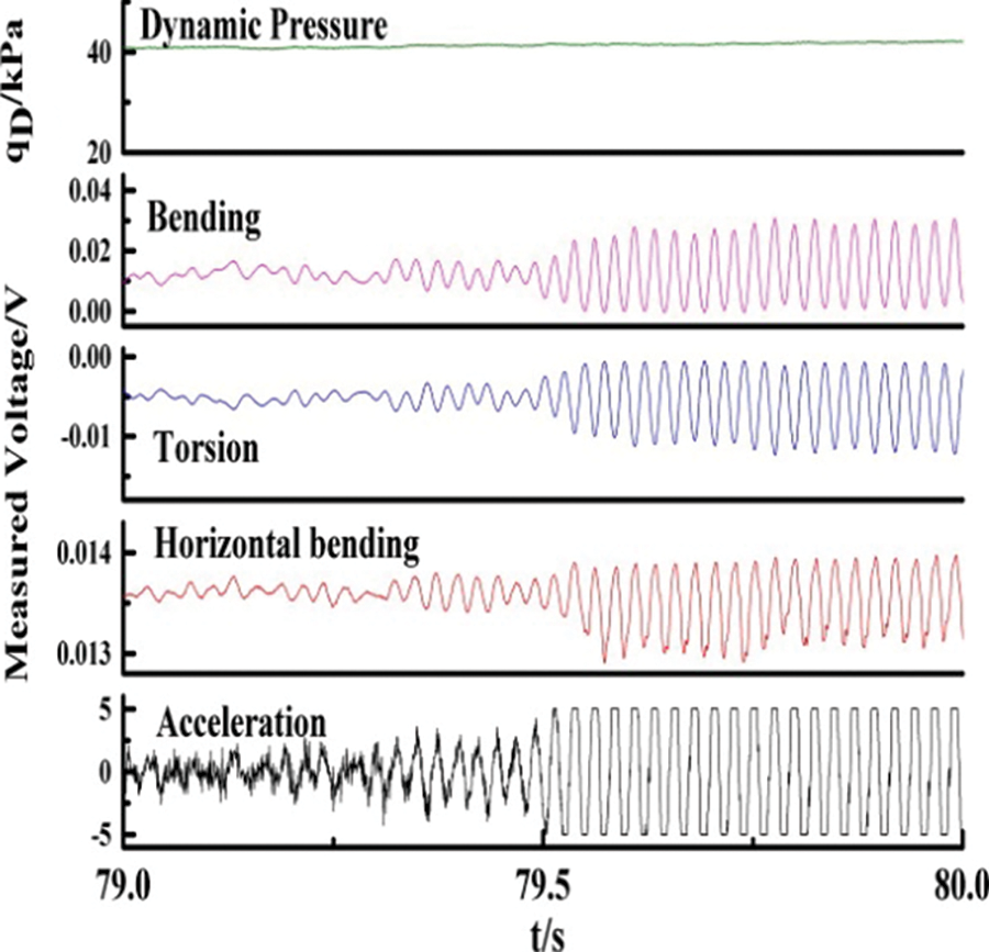
Figure 12: Time history of the critical point of flutter in the wind tunnel experiments at (Ma = 0.7, α = 0°, qD = 41.2 kPa)
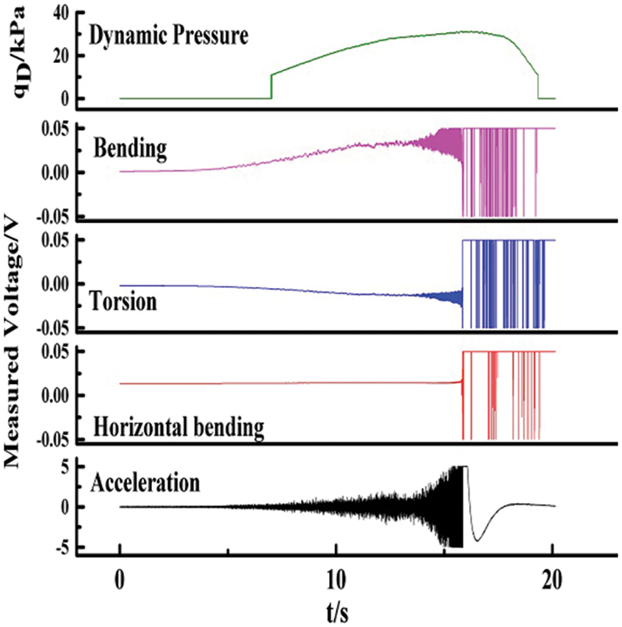
Figure 13: Typical vibration response time history in the wind tunnel experiments at Ma = 0.7 and α = −1°

Figure 14: Time history of the critical point of flutter in the wind tunnel experiments at Ma = 0.7, α = −1°, qD = 30.7 kPa
4.4 Comparison of Simulation and Experimental Results
Table 3 lists the calculated and experimental results for different attack angles at Ma = 0.7. Compared with the experimental results, dynamic pressure errors are controlled within 10%. The simulation and experimental results show that the geometrical nonlinearity caused by large structural deformations with attack angle results in the flutter dynamic pressure decreasing significantly. In particular, the flutter dynamic pressure at α = −1° decreases by approximately 25%.

This study proposed a flutter calculation method based on CFD/CSD considering the large deformation effect. The numerical simulations and wind tunnel experiments were conducted to investigate the high-speed geometric nonlinearities based on the high-aspect-ratio wing. The main conclusions are as follows:
(1) A nonlinear flutter calculation method based on CFD/CSD was proposed, which can be used to calculate high-speed geometrically nonlinear flutter. The performance of the proposed method was verified using wind tunnel experiments.
(2) The large deformation of the wing under load conditions changes its structural properties and reduces the frequency of the in-plane bending vibration.
(3) The geometric nonlinearity of the large deformation of the wing causes the in-plane bending to become a key factor in flutter characteristics, which substantially reduces the nonlinear flutter dynamic pressure and frequency compared to those of the linear flutter.
Acknowledgement: The authors thank TopEdit (www.topeditsci.com) for its linguistic assistance during the preparation of this manuscript.
Funding Statement: The authors received no specific funding for this study.
Conflicts of Interest: The authors declare that they have no conflicts of interest to report regarding the present study.
References
1. Berci, M. (2021). On aerodynamic models for flutter analysis: A systematic overview and comparative assessment. Applied Mechanics, 2(3), 516–541. DOI 10.3390/applmech2030029. [Google Scholar] [CrossRef]
2. He, S., Guo, S., Li, W., Yang, D., Gu, Y. et al. (2020). Nonlinear aeroelastic behavior of an airfoil with free-play in transonic flow. Mechanical Systems and Signal Processing, 138, 106539. DOI 10.1016/j.ymssp.2019.106539. [Google Scholar] [CrossRef]
3. Dos Santos, L. G. P., Marques, F. D. (2021). Nonlinear aeroelastic analysis of airfoil section under stall flutter oscillations and gust loads. Journal of Fluids and Structures, 102, 103250. DOI 10.1016/j.jfluidstructs.2021.103250. [Google Scholar] [CrossRef]
4. Yuan, W., Sandhu, R., Poirel, D. (2021). Fully coupled aeroelastic analyses of wing flutter towards application to complex aircraft configurations. Journal of Aerospace Engineering, 34(2), 04020117. DOI 10.1061/(ASCE)AS.1943-5525.0001232. [Google Scholar] [CrossRef]
5. Conlan-Smith, C., Ramos-García, N., Sigmund, O., Andreasen, C. S. (2020). Aerodynamic shape optimization of aircraft wings using panel methods. AIAA Journal, 58(9), 3765–3776. DOI 10.2514/1.J058979. [Google Scholar] [CrossRef]
6. Silva, G. C., Donadon, M. V., Silvestre, F. J. (2021). Experimental and numerical investigations on the nonlinear aeroelastic behavior of high aspect-ratio wings for different chord-wise store positions under stall and follower aerodynamic load models. International Journal of Non-Linear Mechanics, 131, 103685. DOI 10.1016/j.ijnonlinmec.2021.103685. [Google Scholar] [CrossRef]
7. Patil, M. J., Hodges, D. H. (2004). On the importance of aerodynamic and structural geometrical nonlinearities in aeroelastic behavior of high-aspect-ratio wings. Journal of Fluids and Structures, 19(7), 905–915. DOI 10.1016/j.jfluidstructs.2004.04.012. [Google Scholar] [CrossRef]
8. Shams, S., Sadr Lahidjani, M. H., Haddadpour, H. (2008). Nonlinear aeroelastic response of slender wings based on wagner function. Thin-Walled Structures, 46(11), 1192–1203. DOI 10.1016/j.tws.2008.03.001. [Google Scholar] [CrossRef]
9. Yang, C., Wang, L., Xie, C., Liu, Y. (2012). Aeroelastic trim and flight loads analysis of flexible aircraft with large deformations. Science China Technological Sciences, 55(10), 2700–2711. DOI 10.1007/s11431-012-4912-8. [Google Scholar] [CrossRef]
10. Xie, C., Liu, Y., Yang, C. (2012). Theoretic analysis and experiment on aeroelasticity of very flexible wing. Science China Technological Sciences, 55(9), 2489–2500. DOI 10.1007/s11431-012-4941-3. [Google Scholar] [CrossRef]
11. Xie, C., Yang, C. (2011). Linearization method of nonlinear aeroelastic stability for complete aircraft with high-aspect-ratio wings. Science China Technological Sciences, 54(2), 403–411. DOI 10.1007/s11431-010-4252-5. [Google Scholar] [CrossRef]
12. Arena, A., Lacarbonara, W., Marzocca, P. (2013). Nonlinear aeroelastic formulation and postflutter analysis of flexible high-aspect-ratio wings. Journal of Aircraft, 50(6), 1748–1764. DOI 10.2514/1.C032145. [Google Scholar] [CrossRef]
13. Su, W., Cesnik, C. (2012). Strain-based analysis for geometrically nonlinear beams: A modal approach. 53rd AIAA/ASME/ASCE/AHS/ASC Structures, Structural Dynamics and Materials Conference, pp. 1713. Honolulu, Hawaii. [Google Scholar]
14. Su, W., Cesnik, C. E. S. (2011). Dynamic response of highly flexible flying wings. AIAA Journal, 49(2), 324–339. DOI 10.2514/1.J050496. [Google Scholar] [CrossRef]
15. Kim, K. S., Lee, I., Yoo, J. H., Lee, H. K. (2010). Efficient numerical aeroelastic analysis of a high-aspect-ratio wing considering geometric nonlinearity. Journal of Aircraft, 47(1), 338–343. DOI 10.2514/1.45406. [Google Scholar] [CrossRef]
16. Tang, D. M., Dowell, E. H. (2004). Effects of geometric structural nonlinearity on flutter and limit cycle oscillations of high-aspect-ratio wings. Journal of Fluids and Structures, 19(3), 291–306. DOI 10.1016/j.jfluidstructs.2003.10.007. [Google Scholar] [CrossRef]
17. Yang, C., Xie, L., Xie, C. (2018). Development of aerodynamic methods in aeroelastic analysis for high aspect flexible wings. Acta Aerodynanic Sinica, 36(6), 1009–1018. [Google Scholar]
18. Smith, M. J., Patil, M. J., Hodges, D. H. (2001). CFD-Based analysis of nonlinear aeroelastic behavior of high-aspect ratio wings. 19th AIAA Applied Aerodynamics Conference, Seattle WA. [Google Scholar]
19. Garcia, J. A. (2005). Numerical investigation of nonlinear aeroelastic effects on flexible high-aspect-ratio wings. Journal of Aircraft, 42(4), 1025–1036. DOI 10.2514/1.6544. [Google Scholar] [CrossRef]
20. Nie, X., Huang, C., Yang, G. (2016). Numerical analysis for aeroelastic with structural geometrical nonlinearity using a CFD/CSD-coupled method. Journal of Vibration and Shock, 35(8), 48–53. [Google Scholar]
21. Bendiksen, O. O. (2008). Transonic limit cycle flutter of high-aspect-ratio swept wings. Journal of Aircraft, 45(5), 1522–1533. DOI 10.2514/1.29547. [Google Scholar] [CrossRef]
22. Bartels, R. E., Scott, R. C., Funk, H. J. (2014). Computed and experimental flutter/LCO onset for the boeing truss-braced wing-wind tunnel model. 44th AIAA Fluid Dynamics Conference, pp. 2014–2446. Atlanta, GA. [Google Scholar]
23. Xie, C., Wu, Z., Yang, C. (2003). Aeroelastic analysis of flexible large aspect ratio wing. Journal of Beijing University of Aeronautics and Astronautics, 29(12), 1087–1090. [Google Scholar]
24. Biancolini, M. E., Cella, U., Groth, C., Genta, M. (2016). Static aeroelastic analysis of an aircraft wind-tunnel model by means of modal RBF mesh updating. Journal of Aerospace Engineering, 29(6), 14. DOI 10.1061/(ASCE)AS.1943-5525.0000627. [Google Scholar] [CrossRef]
25. Guo, H., Chen, D., Zhang, C., Lv, B., Wang, X. (2018). Numerical applications on transonic static areoelasticity based on CFD/CSD method. Acta Aerodynamica Sinica, 36(1), 48–53. [Google Scholar]
26. Liu, W., Huang, C., Yang, G. (2017). Time efficient aeroelastic simulations based on radial basis functions. Journal of Computational Physics, 330, 810–827. DOI 10.1016/j.jcp.2016.10.063. [Google Scholar] [CrossRef]
27. Guo, H., Li, G., Chen, D., Lu, B. (2015). Numerical simulation research on the transonic aeroelasticity of a high-aspect-ratio wing. International Journal of Heat and Technology, 33(4), 173–180. DOI 10.18280/ijht. [Google Scholar] [CrossRef]
28. Guo, P., Xie, J. (2019). Two-dimensional CFD modeling of hysteresis behavior of MR dampers. Shock and Vibration, 2019, 1–14. DOI 10.1155/2019/9383047. [Google Scholar] [CrossRef]
Cite This Article
 Copyright © 2023 The Author(s). Published by Tech Science Press.
This work is licensed under a Creative Commons Attribution 4.0 International License , which permits unrestricted use, distribution, and reproduction in any medium, provided the original work is properly cited.
 Downloads
 Citation Tools