
 Submit a Paper
 Propose a Special lssue
 Open Access
ARTICLE

4-Port Octagonal Shaped MIMO Antenna with Low Mutual Coupling for UWB Applications
1 Electrical Engineering Department, College of Engineering, Prince Sattam bin Abdulaziz University, Wadi Addwasir, 11991, Saudi Arabia
2 Electronic and Communication Department, Arab Academy for Science, Technology and Maritime Transport, Cairo, 11865, Egypt
3 Department of Electronics and Communication Engineering, CSPIT, Charotar University of Science and Technology (CHARUSAT), Changa, 388421, India
4 Electronics and Communications Engineering Department, Minia University, El-Minia, 61519, Egypt
* Corresponding Author: Ahmed A. Ibrahim. Email:
Computer Modeling in Engineering & Sciences 2023, 136(2), 1999-2015. https://doi.org/10.32604/cmes.2023.023643
Received 06 May 2022; Accepted 23 September 2022; Issue published 06 February 2023
 View Full Text
 Download PDF
Abstract
A 4-port multiple-input multiple-output (MIMO) antenna exhibiting low mutual coupling and UWB performance is developed. The octagonal-shaped four-antenna elements are connected with a 50 Ω microstrip feed line that is arranged rotationally to achieve the orthogonal polarization for improving the MIMO system performance. The antenna has a wideband impedance bandwidth of 7.5 GHz with S11 < −10 dB from (103.44%) 3.5–11 GHz and inter-element isolation higher than 20 dB. Antenna validation is carried out by verifying the simulated and measured results after fabricating the antenna. The results in the form of omnidirectional radiation patterns, peak gain (≥4 dBi), and Envelope Correlation Coefficient (ECC) (≤0.01) are extracted to validate the suggested antenna performance. As well, time-domain analysis was investigated to demonstrate the operation of the suggested antenna in wideband applications. Finally, the simulated and experimental outcomes have almost similar tendencies making the antenna suitable for its use in UWB MIMO applications.Graphic Abstract
Keywords
Recently, the rapid evolution of modern communication systems motivates researchers to steer their work to wideband technology. The Federal Communications Commission (FCC) is approved bandwidth extended from 3.1 to 10.6 GHz (7.5 GHz) to be utilized in UWB systems [1]. Antennas are considered the most vital part of the UWB modern communication systems because they should fulfill several demands such as wideband feature, compact size, low price, omnidirectional patterns, and the simplicity of integration with the UWB system [2–6].
Multiple-input- multiple-output (MIMO) is considered another technology utilized in communication systems. In MIMO systems, several antennas are used in the transmitting and receiving ends to enhance the data rate and signal quality without increasing the bandwidth and the power of the transmission. The UWB technology is suitable for application scenarios where communication needs to be carried out at a smaller distance because of its weak power and the multipath signal reception problem. So, MIMO technology should be integrated with the UWB technology to increase the channel capacity and fix the multipath signal reception problem. In MIMO systems, the integration of the compact MIMO antennas with the other components is considered the main issue because of the limited available space for the antennas. So, adding antenna elements close to each other is considered the best choice. However, the mutual coupling between elements is increased and isolation techniques should be utilized to reduce the effect of the mutual coupling which increases the complexity of the antenna design [7–11].
Several procedures have been studied for isolation improvement among the antenna elements in the UWB MIMO system. Stubs with different forms are used to enhance the isolation between ports, as discussed in [11–15]. While in [16–20], the isolation is improved by placing the antenna elements in a perpendicular arrangement without any complex use of decoupling structure. Reference [11] discussed four elements of the MIMO antenna using stubs for reducing the undesired mutual coupling. A floating parasitic isolation structure to reduce the mutual coupling is placed between antenna elements [12]. A rectangular stub is added between two antennas, as investigated in [13]. In [14], a resonating stub connected in the ground leads to reduced mutual coupling among the ports. Grounded stubs are used in [15] to improve the isolation between four elements UWB MIMO antenna. In [16], a four ports UWB monopole antenna with a slotted ring radiator and placed orthogonally without utilizing a decoupling structure is introduced. Four elements UWB antenna with CPW fed and four circular slots in the circular radiator are placed orthogonally to enhance the isolation between elements is investigated in [17]. In [19,20], a four ports UWB antenna placed orthogonally to reduce the mutual coupling between elements and without using a decoupling structure is discussed and investigated.
For more simplicity, this paper suggested a 4-port UWB MIMO antenna without using decoupling structures. A 50 Ω microstrip feed line is utilized to feed the four octagonal shape radiator antennas. The isolation is enhanced by adding the elements in a perpendicular arrangement to achieve isolation higher than 20 dB between elements for the desired band of 3.5–11 GHz. The simulation of the antenna is carried out using CST studio. The antenna has a size of 62.5 × 60.5 × 1.6 mm3. The antenna has omnidirectional patterns with a peak gain of >4 dB. The results of the diversity performance of the MIMO are ECC < 0.01, DG ≥ 9.95 within the operating bands. Finally, from the tested results in the form of S-parameters and radiation patterns, it can be claimed that the suggested antenna can be operated in UWB communications.
The development process of the UWB antenna by changing the radiator shape and ground length to match the UWB technology requirement, such as wide bandwidth, small size, and simple design is shown in Fig. 1.
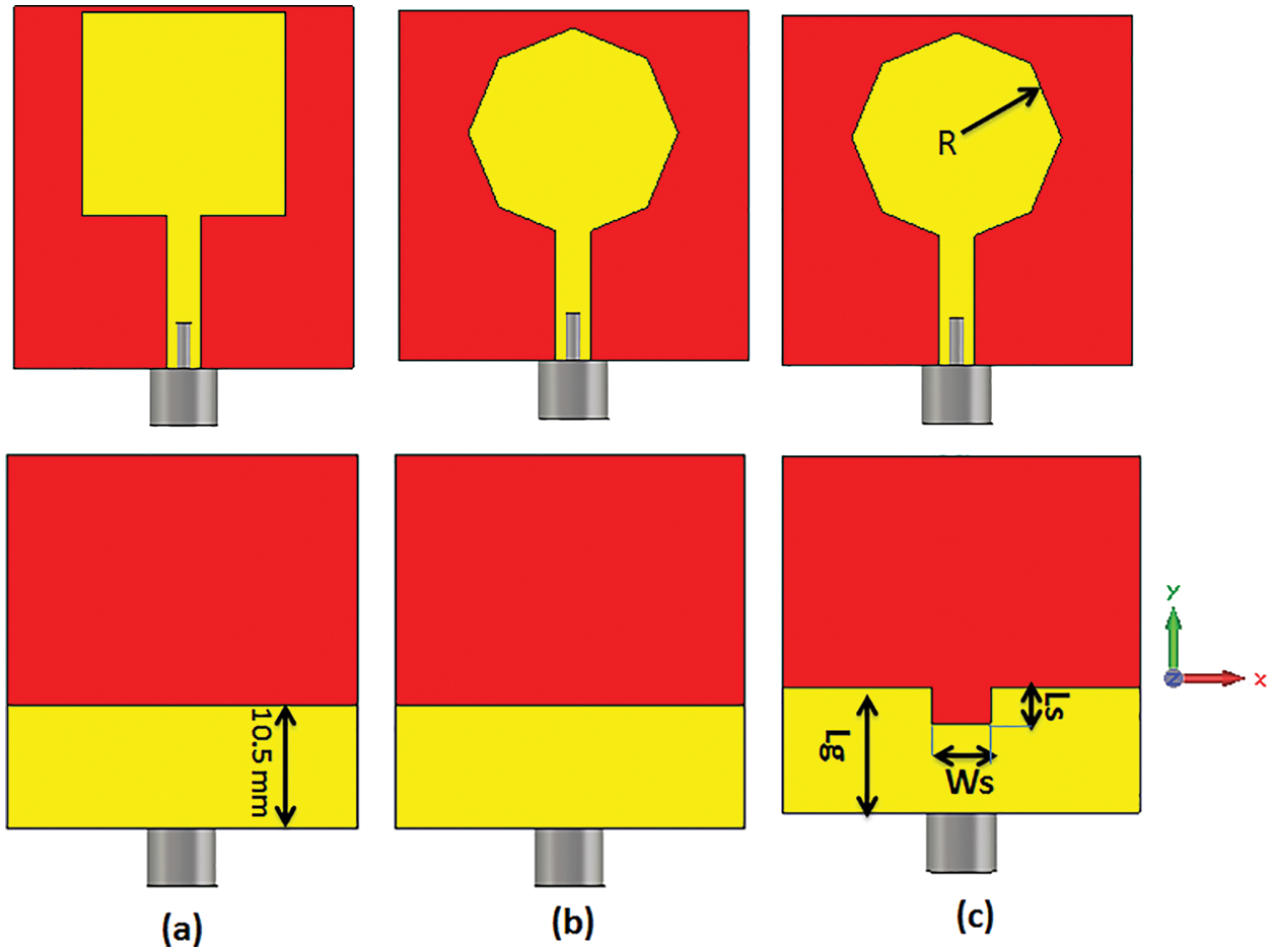
Figure 1: UWB single antenna development (a) Antenna 1 (b) Antenna 2 (c) Proposed antenna
The S11 simulated results are carried out to obtain the proposed structure, as shown in Fig. 2. A rectangular patch (antenna 1) is started as an initial design with a partial ground plane of 10.5 mm as shown in Fig. 1a. The simulated S11 of antenna 1 shows that the antenna operated from (66.66%) 3–6 GHz as illustrated in Fig. 2. To improve the antenna bandwidth, an octagonal shape radiator is utilized as depicted in Fig. 1b (antenna 2) with the same length as the ground plane. Antenna 2 is operated from (78.26%) 3.5–8 GHz with S11 lower than −10 dB and from 10–11 GHz as shown in Fig. 2. Finally, to improve the band from 8–10 GHz small rectangular slot is etched in the bottom as shown in Fig. 1c (antenna 3). The antenna has an impedance bandwidth spanning from (103.44%) 3.5–11 GHz with S11 lower than −10 dB, as seen in Fig. 2, which is suitable for the UWB technology.
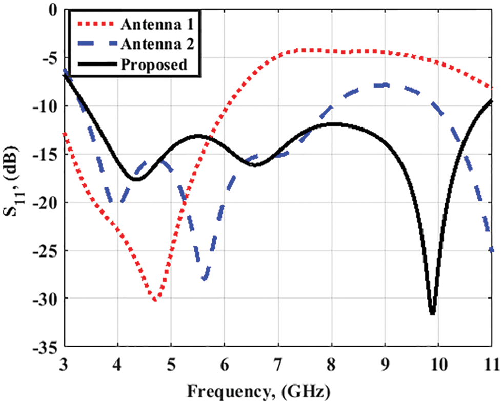
Figure 2: The S11 results of the three antenna structures
To design the antenna to operate at the resonant frequency of 3.5 GHz, the value of the radiator radius is calculated based on the cavity model to excite the dominant mode TM110 as Eq. (1) [21]. Where, fr, εr, and h are the resonant frequency, dielectric constant, and the thickness of the substrate, respectively. Also, to increase the operating bandwidth, the partial ground plane with a rectangular slot is employed as shown in Fig. 1c.
To show the effect of the antenna structure parameters such as the radius (R), the ground length (Lg), the ground slot width (Ws), and length (Ls) on the antenna performance, parametric study analyses are carried out as shown in Fig. 3. As illustrated in Fig. 3a, when the radius (R) is increased from 7 to 11 mm, the first band is shifted from 4 to 3 GHz based on the Eq. (1). The radius (R) equal to 9 mm is used to achieve the recommended results. As shown in Fig. 3b, when the ground length (Lg) is increased from 8.5 to 10.5 mm, the antenna bandwidth and matching are affected. The ground length (Lg) equal to 10.5 mm is used to achieve the proposed results. Also, when the ground slot width (Ws) is increased from 3 to 7 mm, the antenna matching impedance is affected. The ground slot width (Ws) equal to 5 mm is used to achieve the proposed results. Finally, when the ground slot length (Ls) is increased from 1 to 5 mm, the antenna matching impedance is affected. The ground slot length (Ls) equal to 3 mm is used to achieve the proposed results.
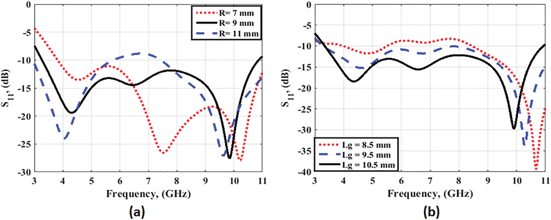
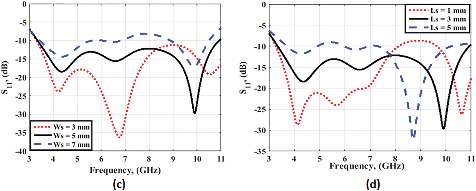
Figure 3: The parametric study results of the proposed octagonal shape antenna (a) The effect of the radius (R) (b) The effect of the ground length (Lg) (c) The effect of the ground slot width (Ws) (d) The effect of the ground slot length (Ls)
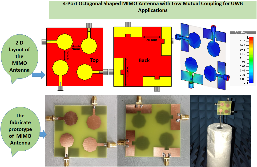
Based on the previous parametric study, the proposed 2D configuration (top and back) of the UWB antenna structure is presented in Fig. 4a, and its fabricated prototype is illustrated in Fig. 4b. The antenna has an octagonal shape radiator connected with a microstrip line matched at 50 Ω. A defected arrangement on the ground plane and a small rectangular slot etched on it are utilized to achieve the required wideband as discussed in the previous paragraph. A cost-efficient FR4 substrate is used in the fabrication process where thickness is 1.6 mm, tan δ is 0.003, and εr = 4.4. The antenna is checked and tested using four ports vector network analyzer (VNA) R&S ZVB 20.
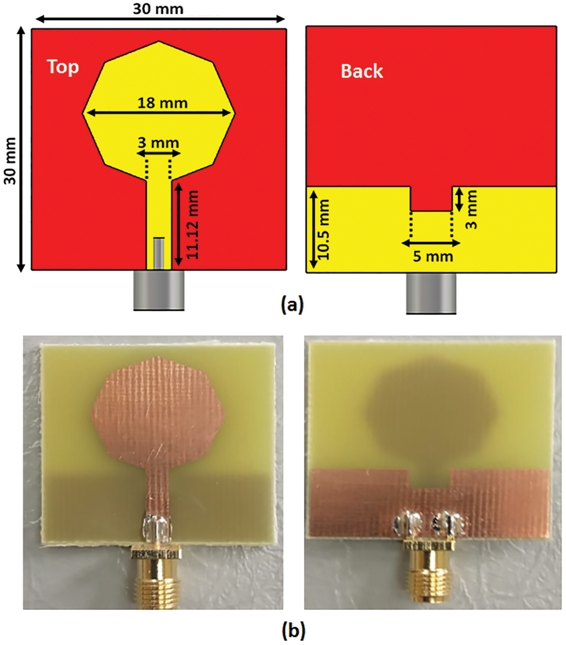
Figure 4: Single antenna geometry (a) 2D configuration layout (b) Fabricated prototype photo
The S11 results are illustrated in Fig. 5. It is clear from the simulated results that, the antenna works in the frequency band from 3.5–11 GHz with S11 ≤ −10 dB while the measured results show almost comparable bandwidth ranging from (97.29%) 3.8–11 GHz However, a small shift between results can be noticed; this could be due to the fabrication and soldering procedure.
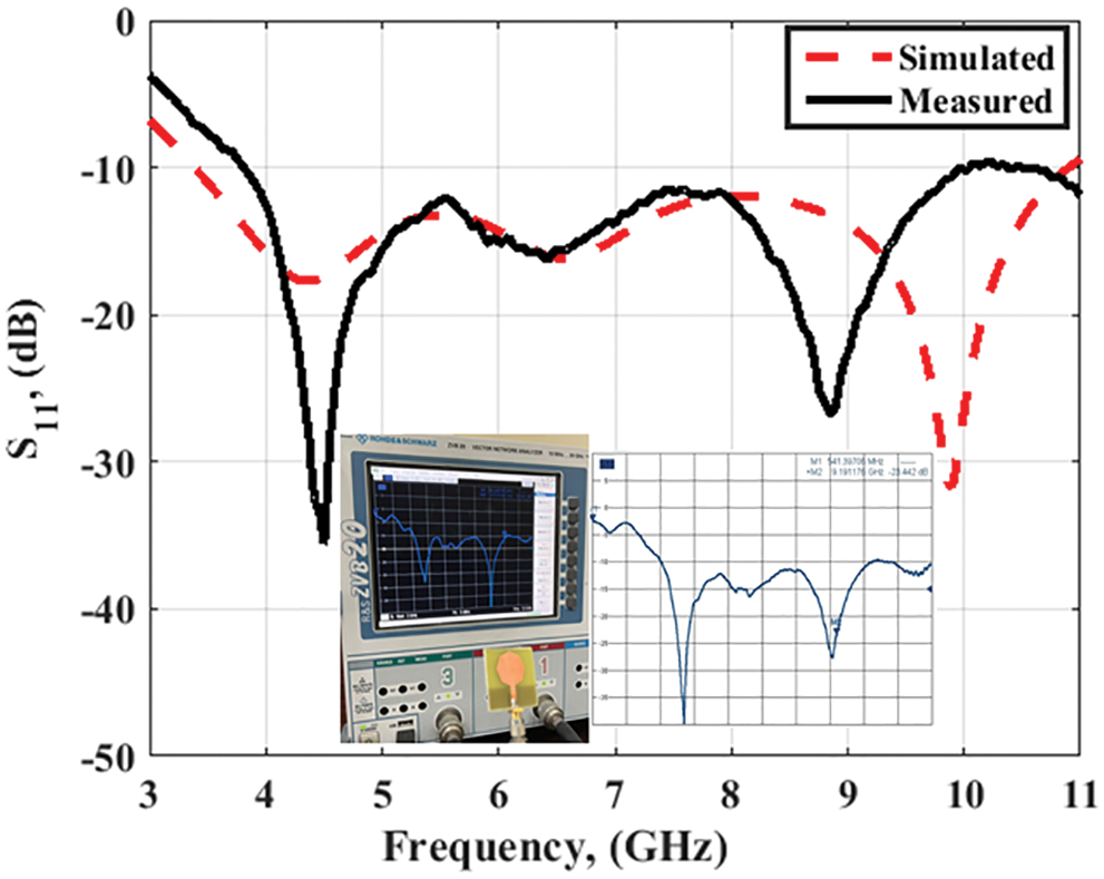
Figure 5: Simulated and measured S11 results of UWB single antenna
To convert the single port to the four ports, the two ports with two configurations side by side and orthogonal orientations with the same edge-to-edge distance of 9 mm between elements are discussed as illustrated in Fig. 6. The orthogonal orientation has good results than the side-by-side configuration. The mutual coupling is enhanced by using the orthogonal orientation without adding extra structures. So, the orthogonal orientation is utilized in the four ports antenna.
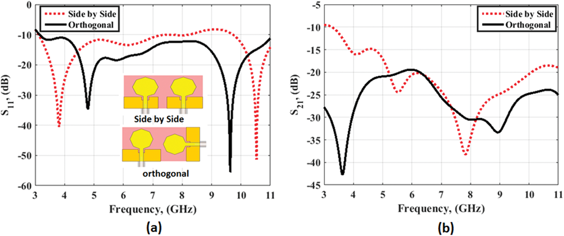
Figure 6: The effect of the two elements’ orientation on the UWB antenna performance at port (a) S11 (b) Isolation (S21)
The single and the two ports UWB antenna discussed in the previous section is arranged to achieve and realize the proposed 4 ports MIMO antenna with 62.5 mm × 60.5 mm as shown in Fig. 7. The antenna in port 1 has an orthogonal orientation with the antenna on port 2, and port 4, and has the same orientation but in opposite direction to the antenna in port 3. This arrangement is utilized to produce the polarization diversity which in turn increases the isolation between elements. The fabricated prototype is demonstrated in Fig. 7b where the same substrate of the single antenna is used in the fabrication process. The measured results are extracted using four ports R&S ZVB 20 VNA from port 1 because of the symmetry property and the other three ports have the same results.
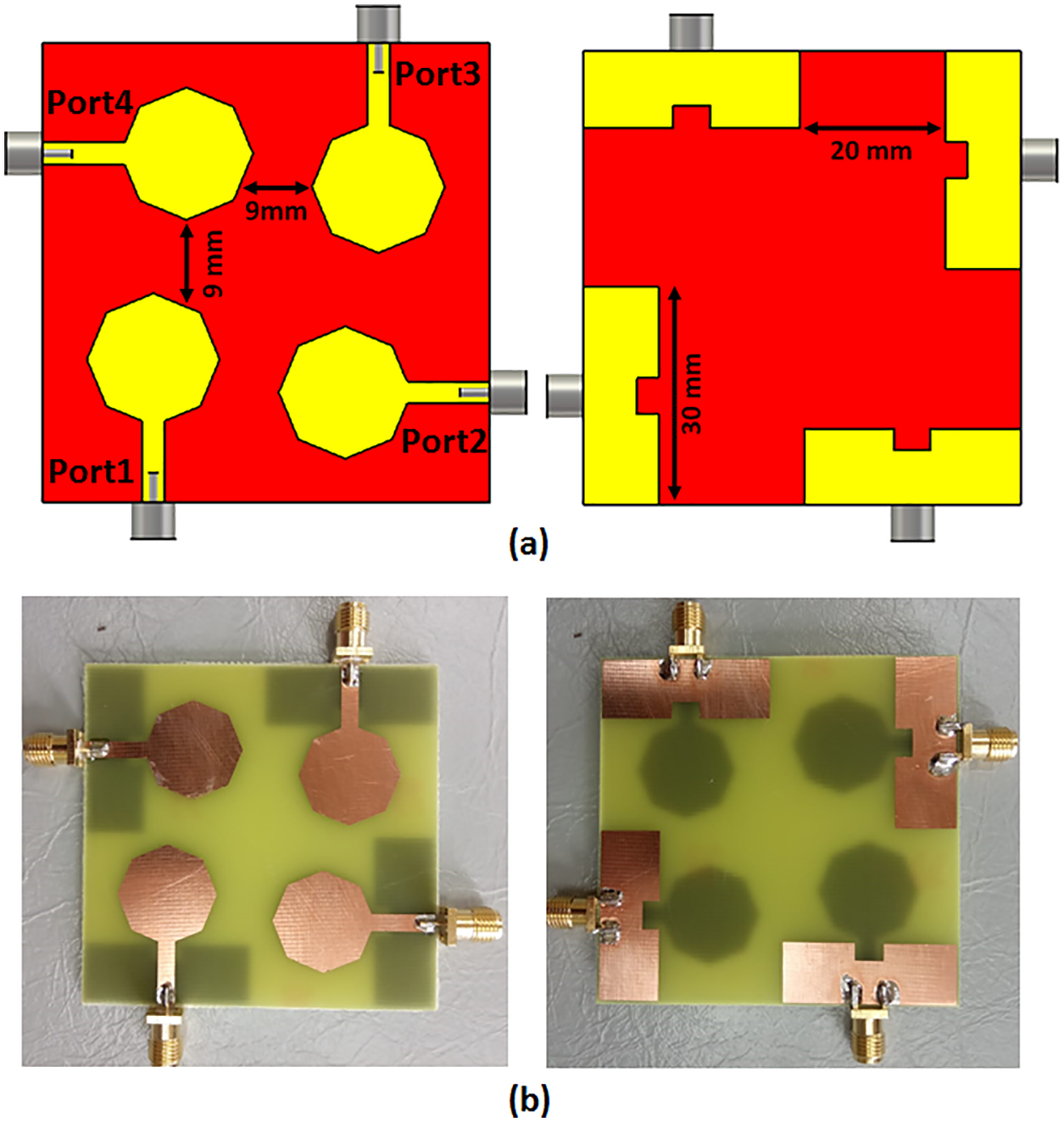
Figure 7: 4-ports UWB MIMO antenna (a) 2-D configuration (b) Fabricated prototype photo
Fig. 8 illustrates the proposed MIMO UWB antenna results at port 1. It is noticed that the simulated results are operated from (103.44%) 3.5–11 GHz with S11 ≤ −10 dB while the measured outcomes show that the antenna almost matched the simulated impedance bandwidth spanning from (97.29%) 3.8–11 GHz. The same trend is observed in both the results with a minor shift due to the fabrication and SMA connector losses. The simulated and measured isolation results at port 1 (S21, S31, S41) are shown in Fig. 9. It is seen that the measured S21 and S41 (perpendicular orientation) have values lower than −20 dB while the S31 has a value lower than −18 dB. Also, the results have good matching between them with the small shift as shown in Fig. 9.
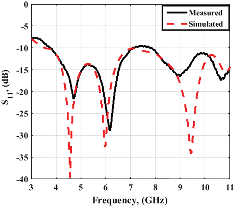
Figure 8: Simulated and measured S11 results of the proposed 4 ports UWB antenna at port 1
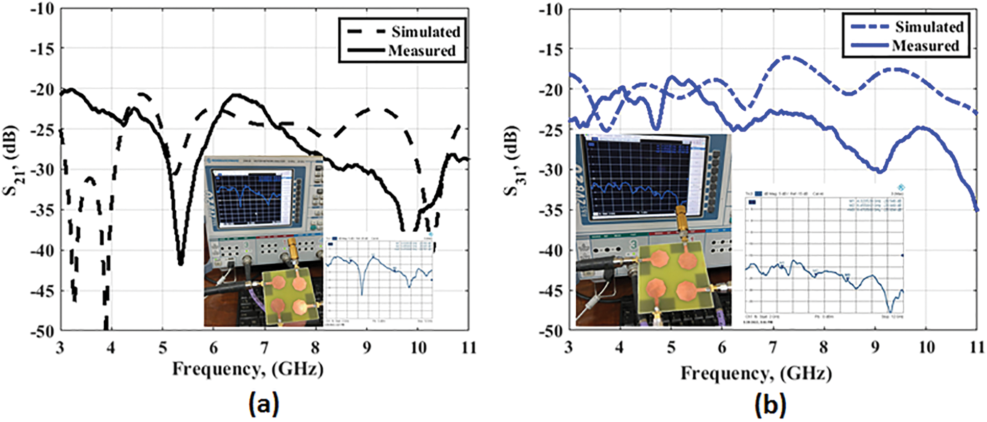
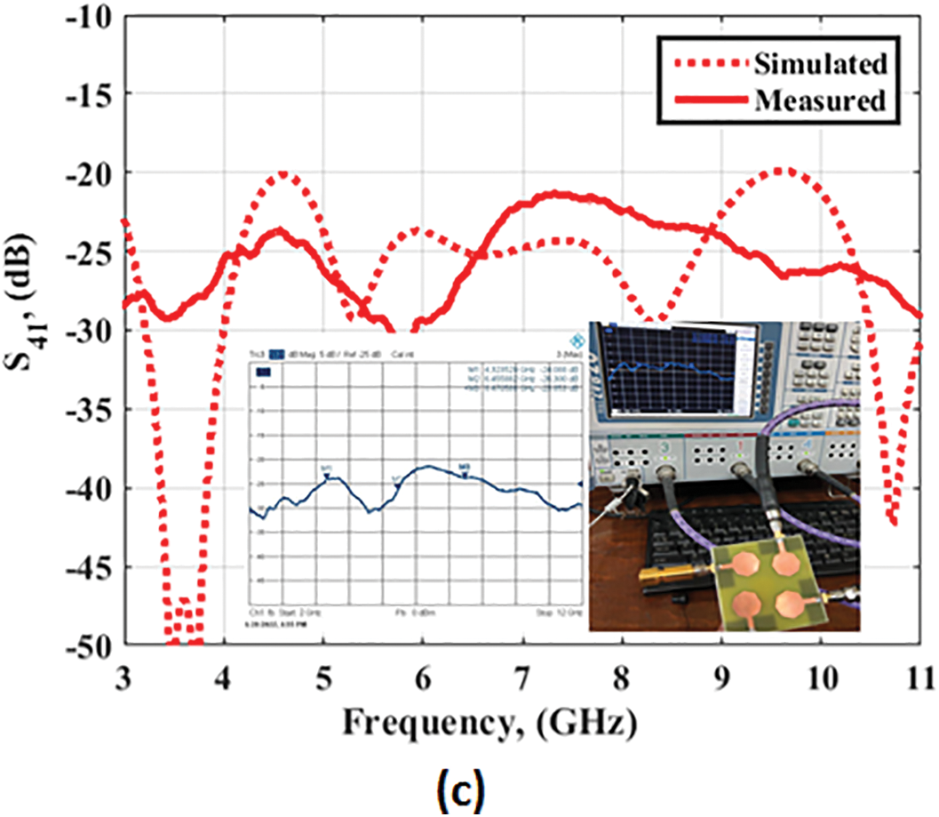
Figure 9: Isolation results of the 4 ports UWB MIMO antenna at port 1 (a) S21 (b) S31 (c) S41
The simulated current distributions of the UWB MIMO antenna at 5 and 8 GHz at four ports are shown in Fig. 10. The current is concentrated around the octagonal patch proving that the antenna radiated at these two frequency bands. Also, the current is confined around the antenna with a very small amount of current dissipated to the other ports which confirm the high isolation between ports.
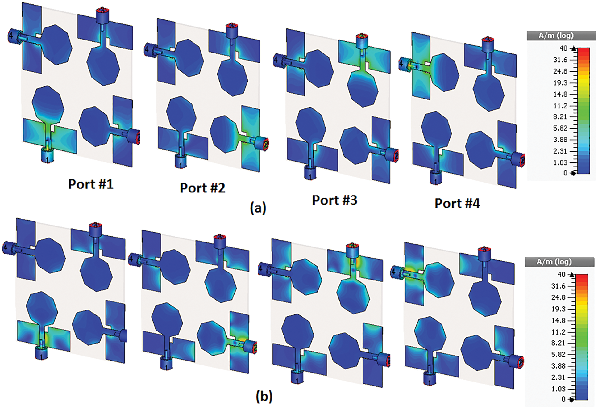
Figure 10: Simulated results of current distributions of the proposed 4 ports UWB antenna (a) @ 5 GHz (b) @ 8 GHz
The 3 D radiation pattern simulation results at 4.5 and 9.5 GHz are illustrated in Fig. 11 to validate the diversity of the patterns. As shown in Fig. 11, when the suggested port is excited the remaining three ports are connected to 50 Ω load. Also, from Fig. 11 it is seen that the 90° phase difference between the ports is achieved to confirm the polarization diversity which in turn enhances the MIMO system.
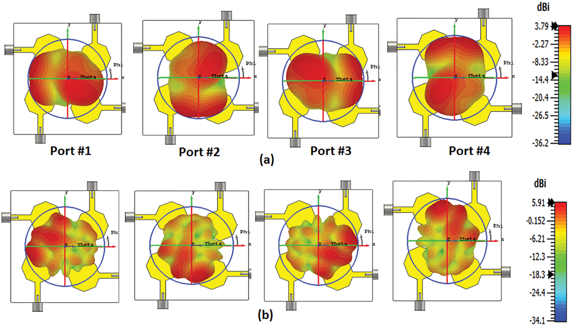
Figure 11: The 3D radiation pattern results of the proposed 4 ports UWB MIMO antenna (a) 4.5 GHz (b) 9.5 GHz
The proposed MIMO antenna radiation patterns and peak gain is measured. Fig. 12 depicts the setup inside an anechoic chamber.
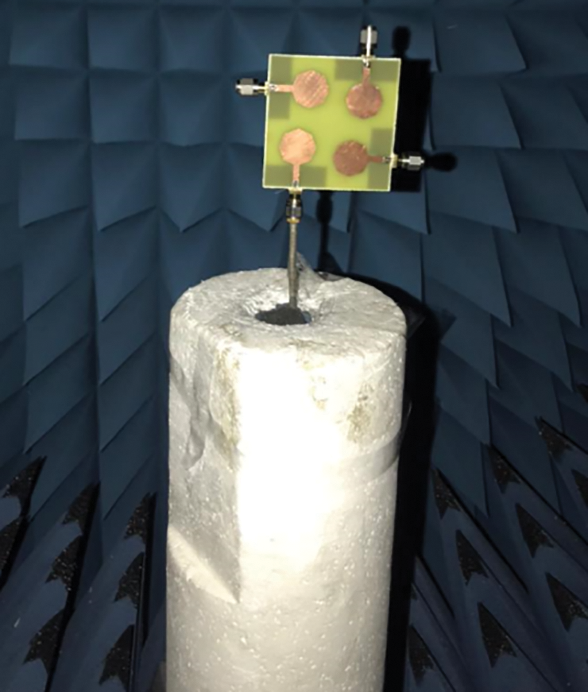
Figure 12: Radiation pattern measurements set up of the 4 ports UWB MIMO antenna @ port 1
The antenna is measured at port 1 where the additional ports are terminated using 50 Ω load. The normalized radiation patterns along x-z/y-z planes at 4.5, 6.5, and 9.5 GHz are illustrated in Fig. 13. It is seen that the antenna has an omnidirectional pattern in the x-z plane and semi-bidirectional in the y-z plane. However, at the higher frequency band, the antenna has omnidirectional patterns in both planes.
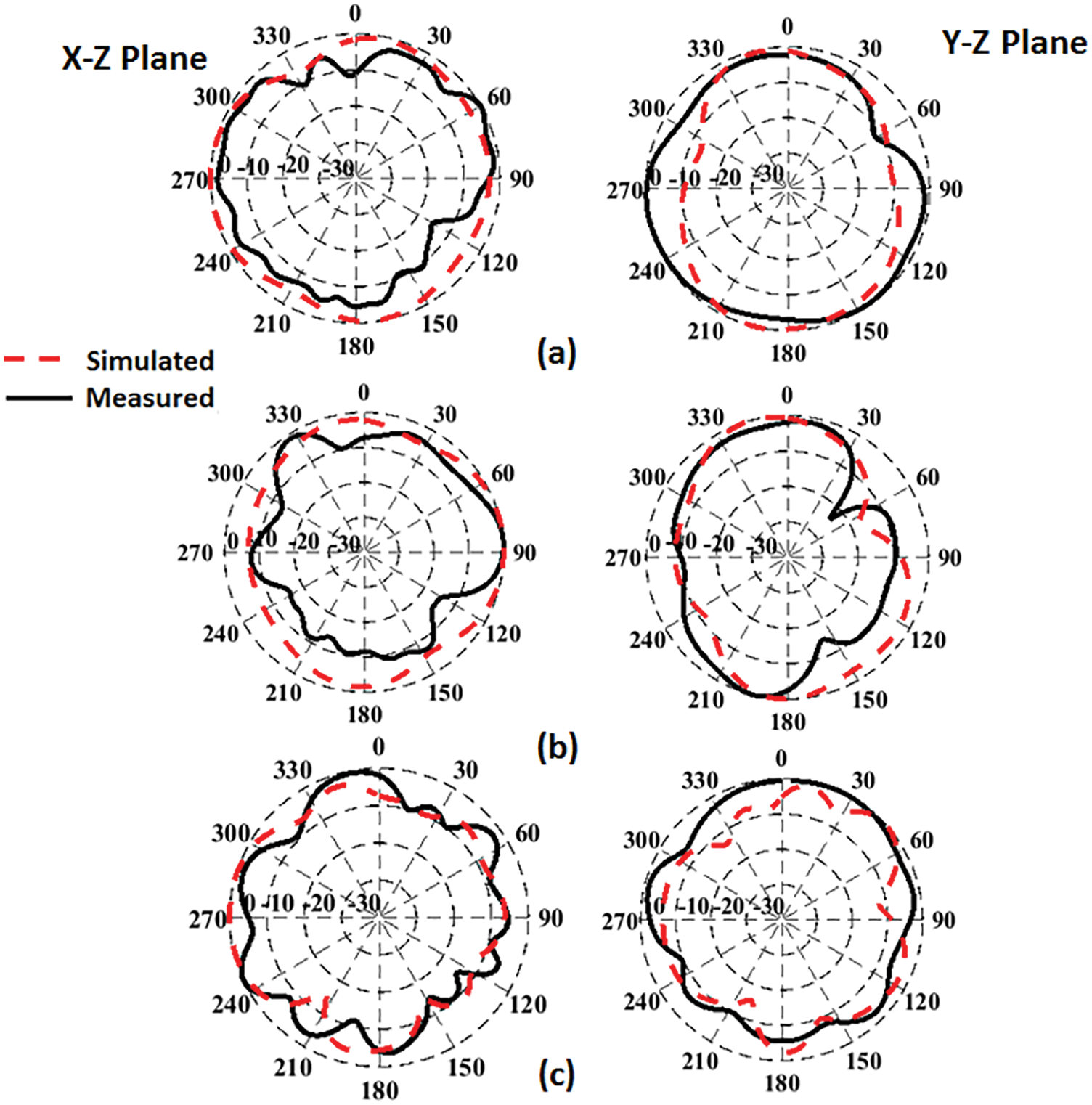
Figure 13: Normalized radiation pattern results of the proposed 4 ports UWB MIMO antenna @ port 1 (a) 4.5 GHz (b) 6.5 GHz (c) 9.5 GHz
Fig. 14 shows the peak gain and simulated total and radiation efficiencies of the MIMO antenna at port 1. From Fig. 14a, the results show that the antenna has peak gain extended from 3.5 to 5.5 dBi within the operated frequency bands with good agreements between the simulated and experimental results. While from Fig. 14b, the results show that the antenna has radiation efficiency extended from 77% to 95% and total efficiency ranging from 70% to 90% within the operated frequency bands. The reduction of the total efficiency especially at higher frequency band is due to the FR4 lossy substrate and the matching impedance of the antenna up to 7 GHz as shown in Fig. 8.
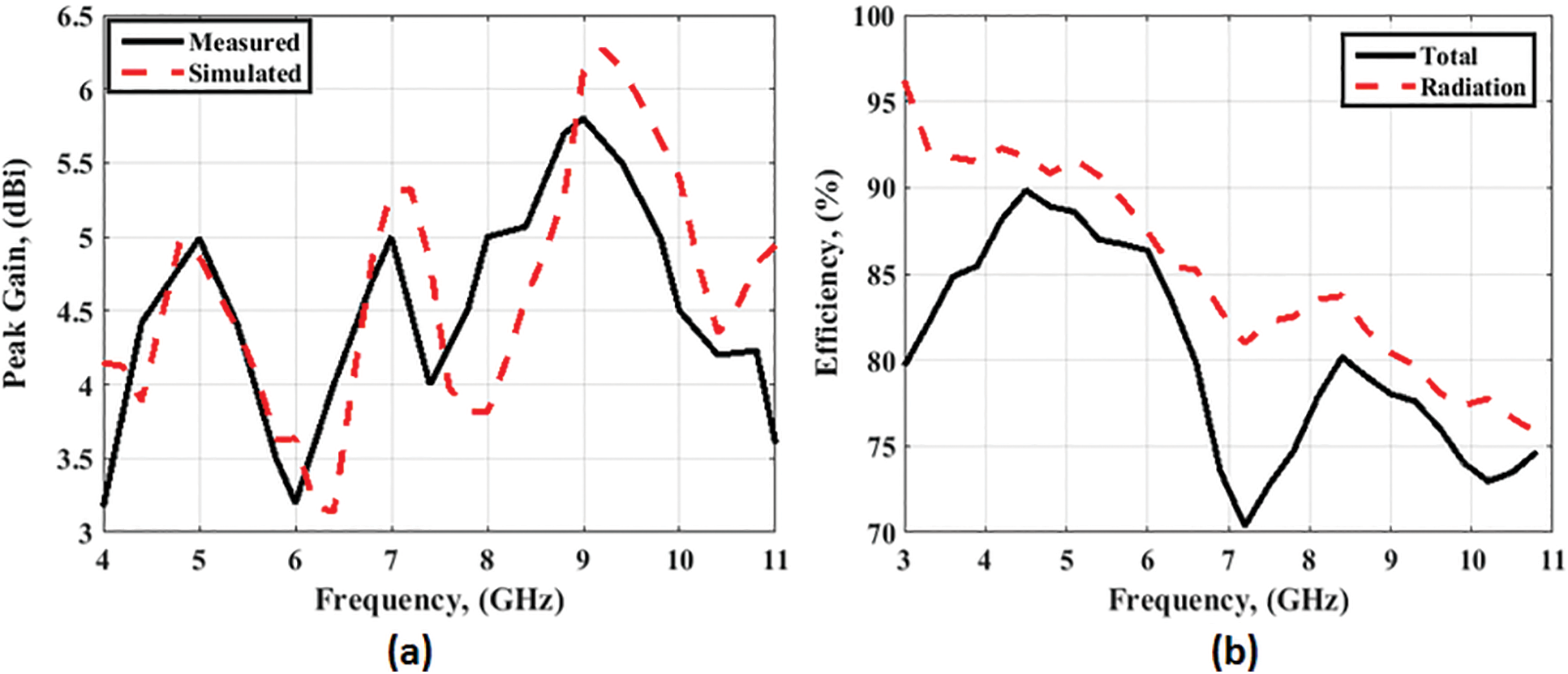
Figure 14: The proposed 4 ports UWB antenna @ port1 (a) Peak gain results (b) Efficiency
The ECC and DG are two parameters to measure the MIMO performance. The ECC measures the relationship between antenna elements in the MIMO system and its value is recommended to be lower than 0.5 and it can be calculated from Eq. (2) [22–24].
Fig. 15 shows the ECC at port 1. It is noticed that the ECC > 0.01 within the band of interest. As well as the DG is connected with the ECC and is calculated from Eq. (3) [22–24].
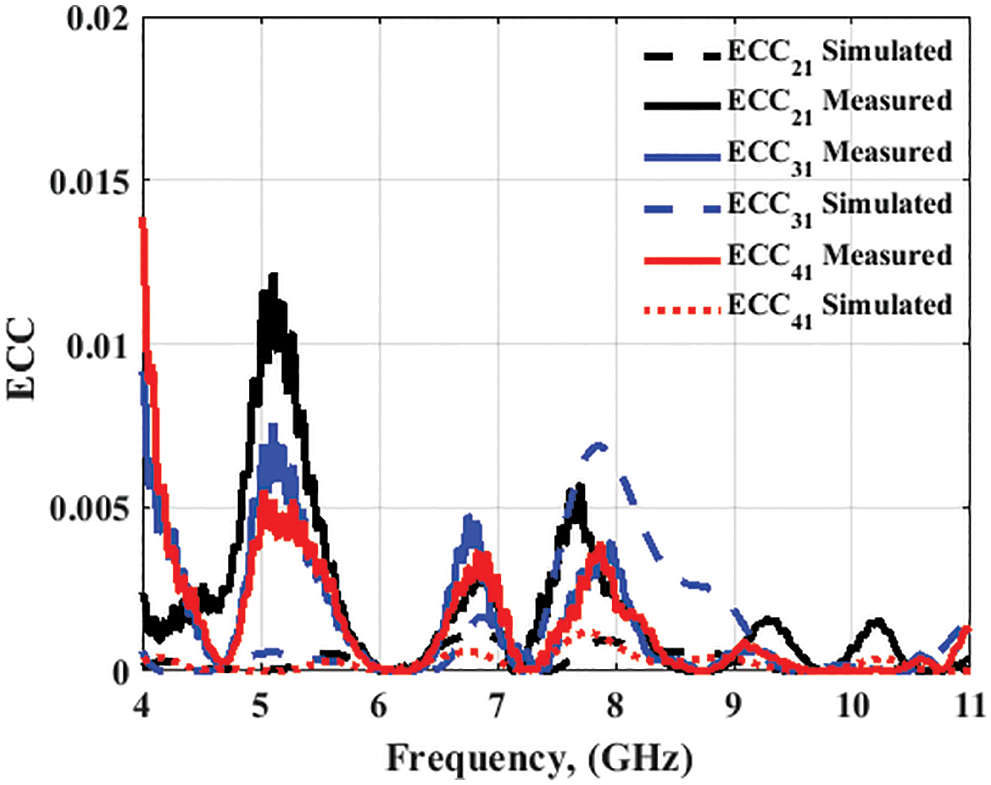
Figure 15: ECC results of the proposed 4 ports UWB antenna
Fig. 16 illustrates the DG where for the band of interest, the value of 9.95 dB is achieved. Also from the results in Figs. 15 and 16, it is noticed that the proposed antenna has good MIMO results which make our antenna suitable for MIMO diversity systems for UWB communication applications.
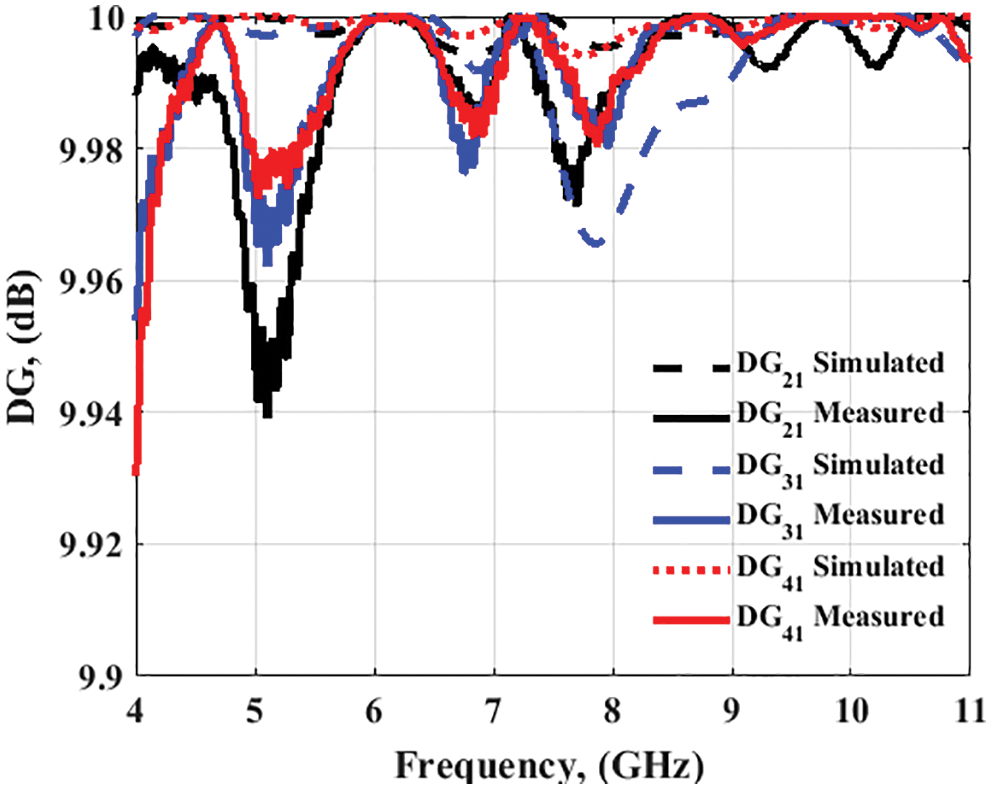
Figure 16: DG results of the proposed 4 ports UWB antenna
4 Simulated Time Domain Analysis
The proposed antenna is checked using time-domain analysis to validate its performance. The antenna in UWB technology transmits a narrow band pulse which means this pulse has a wide-band response in the frequency domain. So, time-domain features as a function of transmission coefficient S21, S21 phase, and group delay are important parameters to show the ability of the antenna to be operated in UWB applications. Fig. 17 illustrates the simulated time-domain setup at different three layouts (face to face, face to side, and side by side). The two similar antennas are placed in three different configurations maintaining a distance of 210 mm (2.45 times λ0 at 3.5 GHz) between them. One antenna behaves as the transmitter (Tx) while the other acts as the receiver (Rx).
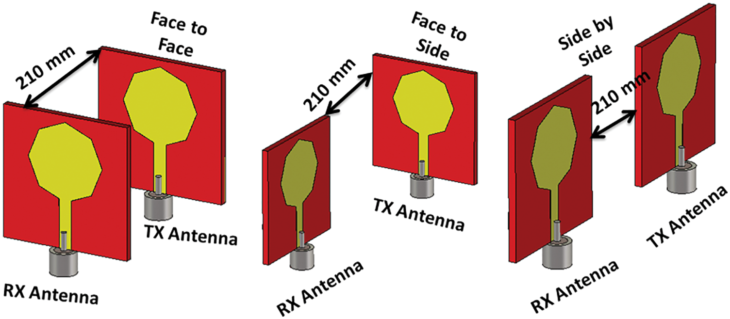
Figure 17: Simulated time-domain analysis setup at different layout
Fig. 18 shows the magnitudes of the S21, S21 phases, and the unwrapped S21 phase. It is clear from Fig. 18a that the three antenna configurations have an S21 value lower than −30 dB throughout the entire frequency band with a stable value from 3.5–9 GHz while at the higher frequency band from 10 to 11 GHz the value is reduced lower than −40 dB, especially at the face to face and face to side configurations. As well, the S21 phase is shown in Fig. 18b and the unwrapped phase for better observation is illustrated in Fig. 18c to know the linearity features within the wideband operation. It is seen from the phase curves that the antenna has linear operation within the frequency band at different configurations. For more confirmation, group delay results are illustrated in Fig. 19. It is seen that the group delay has a stable value of around 1.1 ns within the operating frequency band with around 0.1 ns variation at the end of the band, especially at the two face-to-face and face-to-side configurations. Table 1 illustrates the suggested work in comparison to other former works. The suggested work has a simple design, high isolation, and high gain which suggests it be employed in the UWB MIMO systems.
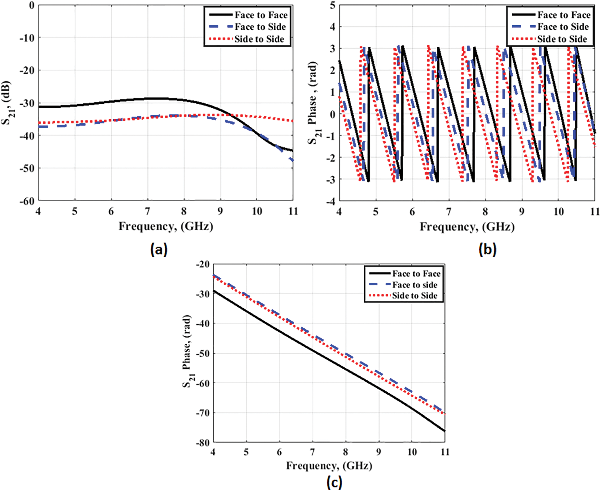
Figure 18: Simulated results at the different layout (a) S21 (b) S21 phase (c) S21 unwrapped phase
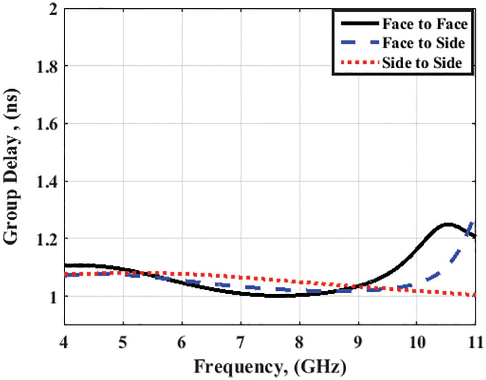
Figure 19: Simulated group delay results at different layout
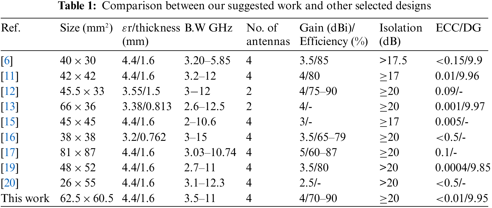
The antenna is compared with the existing MIMO antennas from the literature in Table 1. It is observed that the antenna has a low profile, wide bandwidth, 4-port configuration, high gain, low mutual coupling without using a complex decoupling structure, and low ECC value that qualifies the antenna for its use in UWB MIMO applications.
A four-port MIMO antenna for UWB operation has been investigated in this paper. The suggested antenna element, as the initial design, is first fabricated and tested. After that, 4 ports MIMO antenna with perpendicular arrangement has been discussed, simulated, fabricated, and tested using VNA. As well, radiation patterns, peak gain, and MIMO performance have been investigated. The suggested antenna has been worked at a frequency band extending from 3.5 to 11 GHz with more than 20 dB, 4 dBi isolation between ports, and peak gain, respectively. The time response has been discussed to validate the suggested antenna to operate in wideband applications. Finally, the proposed antenna has been compared with other antennas, and the results show that the suggested antenna can be used in UWB communication.
Funding Statement: The authors received no specific funding for this study.
Conflicts of Interest: The authors declare that they have no conflicts of interest to report regarding the present study.
References
1. First Report and Order (2002). Revision of part 15 of the commission’s rule regarding ultra-wideband transmission system FCC 02-48. Federal Communications Commission. http://www.sss-mag.com/pdf/retrieve.pdf. [Google Scholar]
2. Boutejdar, A., Ibrahim, A. A., Burte, E. P. (2015). Novel microstrip antenna aims at UWB applications. Microwaves & RF Magazine, 7(7), 8–14. [Google Scholar]
3. Dhasarathan, V., Sharma, M., Kapil, M., Vashist, P. C., Patel, S. K. et al. (2020). Integrated bluetooth/LTE2600 superwideband monopole antenna with triple notched (WiMAX/WLAN/DSS) band characteristics for UWB/X/Ku band wireless network applications. Wireless Networks, 26(4), 2845–2855. DOI 10.1007/s11276-019-02230-0. [Google Scholar] [CrossRef]
4. Ali, W., Ibrahim, A. A., Machac, J. (2017). Compact size UWB monopole antenna with triple band-notches. Radioengineering, 26(1), 57–63. [Google Scholar]
5. Yadav, R., Malviya, L. (2020). UWB antenna and MIMO antennas with bandwidth, band-notched, and isolation properties for high-speed data rate wireless communication: A review. International Journal of RF and Microwave Computer-Aided Engineering, 30(2), e22033. DOI 10.1002/mmce.22033. [Google Scholar] [CrossRef]
6. Kulkarni, J., Desai, A., Sim, C. Y. D. (2021). Wideband Four-Port MIMO antenna array with high isolation for future wireless systems. AEU-International Journal of Electronics and Communications, 128, 153507. DOI 10.1016/j.aeue.2020.153507. [Google Scholar] [CrossRef]
7. Farahani, M., Mohammad-Ali-Nezhad, S. (2020). A novel UWB printed monopole MIMO antenna with non-uniform transmission line using nonlinear model predictive. Engineering Science and Technology, an International Journal, 23(6), 1385–1396. DOI 10.1016/j.jestch.2020.05.006. [Google Scholar] [CrossRef]
8. Ali, W. A., Ibrahim, A. A. (2017). A compact double-sided MIMO antenna with an improved isolation for UWB applications. AEU-International Journal of Electronics and Communications, 82, 7–13. DOI 10.1016/j.aeue.2017.07.031. [Google Scholar] [CrossRef]
9. Tang, T. C., Lin, K. H. (2014). An ultrawideband MIMO antenna with dual band-notched function. IEEE Antennas and Wireless Propagation Letters, 13, 1076–1079. DOI 10.1109/LAWP.2014.2329496. [Google Scholar] [CrossRef]
10. Wu, D., Cheung, S. W., Li, Q. L., Yuk, T. I. (2017). Decoupling using diamond-shaped patterned ground resonator for small MIMO antennas. IET Microwaves, Antennas & Propagation, 11(2), 177–183. DOI 10.1049/iet-map.2016.0400. [Google Scholar] [CrossRef]
11. Aboelleil, H., Ibrahim, A. A., Khalaf, A. A. (2021). A compact multiple-input multiple-output antenna with high isolation for wireless applications. Analog Integrated Circuits and Signal Processing, 108, 17–24. DOI 10.1007/s10470-020-01775-x. [Google Scholar] [CrossRef]
12. Khan, M. S., Capobianco, A. D., Najam, A. I., Shoaib, I., Autizi, E. et al. (2014). Compact ultra-wideband diversity antenna with a floating parasitic digitated decoupling structure. IET Microwaves, Antennas & Propagation, 8, 747–753. DOI 10.1049/iet-map.2013.0672. [Google Scholar] [CrossRef]
13. Ali, W. A., Ibrahim, A. A., Mohamed, H. A. (2019). Highly isolated Two elements MIMO antenna with band-notched characteristics for UWB applications. 6th International Conference on Advanced Control Circuits and Systems (ACCS) & 2019 5th International Conference on New Paradigms in Electronics & Information Technology (PEIT), pp. 77–81. Hurgada, Egypt. [Google Scholar]
14. Khan, M. S., Capobianco, A. D., Iftikhar, A., Shubair, R. M., Anagnostou, D. E. et al. (2017). Ultra-compact dual-polarised UWB MIMO antenna with meandered feeding lines. IET Microwaves, Antennas & Propagation, 11(7), 997–1002. DOI 10.1049/iet-map.2016.1074. [Google Scholar] [CrossRef]
15. Tripathi, S., Mohan, A., Yadav, S. (2015). A compact Koch fractal UWB MIMO antenna with WLAN band-rejection. IEEE Antennas and Wireless Propagation Letters, 14, 1565–1568. DOI 10.1109/LAWP.2015.2412659. [Google Scholar] [CrossRef]
16. Sipal, D., Abegaonkar, M. P., Koul, S. K. (2017). Easily extendable compact planar UWB MIMO antenna array. IEEE Antennas and Wireless Propagation Letters, 16, 2328–2331. DOI 10.1109/LAWP.2017.2717496. [Google Scholar] [CrossRef]
17. Srivastava, K., Kumar, A., Kanaujia, B. K., Dwari, S., Kumar, S. (2019). A CPW-fed UWB MIMO antenna with integrated GSM band and dual band notches. International Journal of RF and Microwave Computer Aided Engineering, 29(1), 21433. DOI 10.1002/mmce.21433. [Google Scholar] [CrossRef]
18. Khan, M. S., Capobianco, A. D., Naqvi, A., Ijaz, B., Asif, S. et al. (2015). Planar, compact ultra-wideband polarisation diversity antenna array. IET Microwaves, Antennas & Propagation, 9(15), 1761–1768. DOI 10.1049/iet-map.2015.0371. [Google Scholar] [CrossRef]
19. Ibrahim, A. A., Ali, W. A. (2022). High isolation 4-element ACS-fed MIMO antenna with band notched feature for UWB communications. International Journal of Microwave and Wireless Technologies, 14(1), 54–64. DOI 10.1017/S175907872100009X. [Google Scholar] [CrossRef]
20. Toktas, A., Akdagli, A. (2015). Compact multiple-input multiple-output antenna with low correlation for ultra-wide-band applications. IET Microwaves, Antennas & Propagation, 9(8), 822–829. DOI 10.1049/iet-map.2014.0086. [Google Scholar] [CrossRef]
21. Balanis, C. A. (2015). Antenna theory: Analysis and design. USA: John Wiley & Sons. [Google Scholar]
22. Desai, A., Palandoken, M., Kulkarni, J., Byun, G., Nguyen, T. K. (2021). Wideband flexible/transparent connected-ground MIMO antennas for Sub-6 GHz 5G and WLAN applications. IEEE Access, 9, 147003–147015. DOI 10.1109/ACCESS.2021.3123366. [Google Scholar] [CrossRef]
23. Ibrahim, A. A., Ali, W. A. (2021). High gain, wideband and low mutual coupling AMC-based millimeter wave MIMO antenna for 5G NR networks. AEU-International Journal of Electronics and Communications, 142, 153990. DOI 10.1016/j.aeue.2021.153990. [Google Scholar] [CrossRef]
24. Desai, A., Kulkarni, J., Kamruzzaman, M. M., Hubálovský, Š., Hsu, H. T. et al. (2022). Interconnected CPW Fed flexible 4-port MIMO antenna for UWB, X, and Ku band applications. IEEE Access, 10, 57641–57654. DOI 10.1109/ACCESS.2022.3179005. [Google Scholar] [CrossRef]
Cite This Article
 Copyright © 2023 The Author(s). Published by Tech Science Press.
This work is licensed under a Creative Commons Attribution 4.0 International License , which permits unrestricted use, distribution, and reproduction in any medium, provided the original work is properly cited.
 Downloads
 Citation Tools