 Open Access
ARTICLE
Finite Element Implementation of the Exponential Drucker–Prager Plasticity Model for Adhesive Joints
1 Department of Mechanical and Aerospace Engineering, Faculty of Engineering, King Mongkut’s University of Technology North Bangkok, Bangkok, 10800, Thailand
2 Department of Teacher Training in Civil Engineering, Faculty of Technical Education, King Mongkut’s University of Technology North Bangkok, Bangkok, 10800, Thailand
3 KMUTNB–TU Chemnitz Collaborative Center for Lightweight Structures Technologies (LiST), King Mongkut’s University of Technology North Bangkok, Bangkok, 10800, Thailand
* Corresponding Author: Arisara Chaikittiratana. Email:
Computer Modeling in Engineering & Sciences 2023, 135(3), 1765-1778. https://doi.org/10.32604/cmes.2023.022523
Received 14 March 2022; Accepted 12 July 2022; Issue published 23 November 2022
Abstract
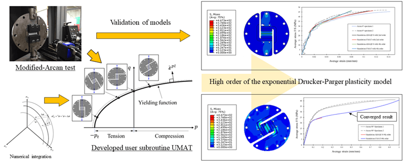
This paper deals with the numerical implementation of the exponential Drucker-Parger plasticity model in the commercial finite element software, ABAQUS, via user subroutine UMAT for adhesive joint simulations. The influence of hydrostatic pressure on adhesive strength was investigated by a modified Arcan fixture designed particularly to induce a different state of hydrostatic pressure within an adhesive layer. The developed user subroutine UMAT, which utilizes an associated plastic flow during a plastic deformation, can provide a good agreement between the simulations and the experimental data. Better numerical stability at highly positive hydrostatic pressure loads for a very high order of exponential function can also be achieved compared to when a non-associated flow is used.
Graphic Abstract
Keywords
Nomenclature
| ∆ε | Total strain increment tensor |
| ∆εel | Elastic strain increment tensor |
| ∆εpl | Plastic strain increment tensor |
| ∆σ | Stress increment tensor |
| D | Constitutive tensor of isotropic liner elastic materials |
| dλ | Plastic multiplier |
| g | Plastic potential function |
| n, m | Plastic strain rate direction |
| g | Plastic potential function |
| ξ | Eccentricity of hyperbolic function defined an approaching rate of function to its asymptotes |
| β | Dilation angle measured in the p−σeff plane |
| σeff | Equivalent von Mises stress |
| p | Hydrostatic pressure |
| pt | Hardening constant |
| σy | Yield stress |
| a, b | Material parameters that are independent to plastic deformation |
| σ11, σ22, σ33 | Normal stress components |
| σ12, σ13, σ23 | Shear stress components |
| pt0 | Hardening constant at yield |
| εpleq | Equivalent plastic strain |
| Hpt | Plastic shear hardening |
| H | Hardening coefficient |
| q, c | Material constants of hardening |
Structural adhesives have been widely used in the aerospace, aviation, shipbuilding, and automotive industries due to a variety of benefits, including multi-material bonding, good load distribution across bonded areas, less environmental degradation, and a simple manufacturing process. It is also relatively inexpensive when compared to other joining methods [1,2]. To effectively use adhesives, it is necessary to forecast the behavior of adhesive joints under complex loading combinations. As a polymer, adhesives’ mechanical behavior and failure rely on hydrostatic pressure, strain rate, and temperature [3]. In typical applications, hydrostatic pressure is the most visible factor influencing the mechanical behavior of polymers. It has a significant impact in polymer yield strength, plastic flow, strain hardening, and failure plasticity [4]. The effect of hydrostatic pressure on material yield strength can be explained by the Drucker-Prager yield criterion, which is a modified version of the von Mises criterion as a function of hydrostatic pressure. The model was originally a linear function and was developed to predict the failure of soil [5]. The exponential version of this criterion shows a good prediction of polymer base material behavior [6]. Despite the development of yield functions in previous works [7], the flow function for plastic deformation is limited to a linear function, resulting in a non-associated flow when using the exponential Drucker-Prager yield criterion. With this type of flow, the simulations are prone to diverge when subjected to a serious tri-axial load in tension or negative hydrostatic pressure, which is a critical load case for adhesives [8].
This article presents the numerical implementation of the exponential Drucker-Parger plasticity model in the commercial finite element software ABAQUS through the user subroutine UMAT. The development of subroutines was restricted to elastoplastic behavior, and for yield surface modification, only hydrostatic pressure was considered. The associated flow during plastic deformation was expected to increase the numerical stability for adhesive joint simulations. The experimental findings from specialized testing using the modified Arcan fixture [9], which is specifically intended to produce a distinct state of hydrostatic pressure inside an adhesive layer, were utilized to validate the developed model. Experiments and simulations using the second exponential Drucker-Parger model correlated well.
From the classical plasticity theory, the total strain increment for an elastoplastic model can be decomposed into elastic and plastic strain increments. For 3D problems, they are represented by 2nd tensor forms as follows:
Based on Hooke’s law, the incrementation of stress-strain relationship in the elastic deformation is written as follows:
A general form of flow rules for plastic behavior is written as:
The associated flow is achieved when the plastic potential function is the same as the yield function (g = f). For this flow, the plastic flow direction will always be normal to the yield surface. Fig. 1 depicts an associated where g = f and non-associated flow where g ≠ f. The plastic flow direction is perpendicular to the function g in the case of non-associated flow.
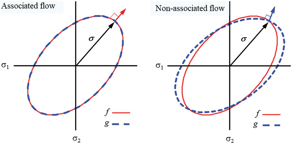
Figure 1: Concept of the associated flow rule and non-associated flow rule
The flow rules in commercial finite element software are commonly non-associated flows since they can be used for a variety of purposes. In this case, an implicit return mapping algorithm (backward Euler method) is used for high precision calculations into the program [10]. In some load cases, the difference between a plastic potential function and a yield function causes the calculation to diverge. Eq. (4) is the plastic potential function for the exponential Drucker-Prager model in ABAQUS software, which is also non-associated flow.
The hyperbolic function is the only available option for the plastic potential function in ABAQUS when using a general exponent yield criterion. The 2nd order exponential Drucker-Prager yield criteria (parabolic function) is recommended even though the order of exponential Drucker-Prager yield criteria can be arbitrary [11]. In the next section, this non-associated flow from ABAQUS will be compared to the model that was made with an associated flow.
The numerical integration method is required in order to solve the elastoplastic differential equations. The common methods used in computational processes are the forward Euler method, the backward Euler method, and the midpoint method. While the forward Euler method is the simplest computational process, it has a limit on computational stability and high error responses. The backward Euler method is more complex than the forward Euler method but highly accurate for the increase of stress that affects the yield surface expansion. The method is also very stable in terms of computation [12]. For this reason, the backward Euler method is very popular for solving elastoplastic. Its equation is written as in Eq. (5) and Fig. 2 illustrates its approximation step.
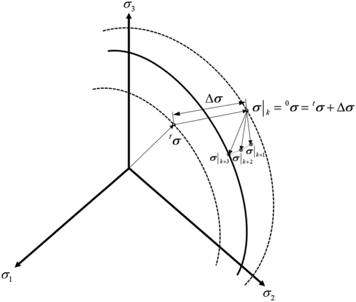
Figure 2: Numerical integration of the elastoplastic equations
With
The residual vector is then defined as follows:
According to the associated flow rule, the plastic strain increment can be defined as follows:
where ∆λ is the plastic multiplier and a is the flow vector. Substituting the flow vector into Eq. (7).
Then, applying the Newton-Raphson method in the residual vector (Eq. (9)).
Thus
where
A is a second order derivativities tensor of yield function, thus
Substituting Eqs. (11) and (12) into Eq. (10), then the increased stress can be finally determined by rearranging Eqs. (13) to (14).
The exponential Drucker-Prager models are expressed as follows:
where σeff is von Mises stress, p is hydrostatic pressure, pt is hardening constant, a and b are material parameters that are independent to plastic deformation.
The von Mises stress and hydrostatic pressure are defined as Eqs. (16) and (17). The strain hardening for the Drucker–Prager model is defined by the multilinear method in plastic shear hardening where hydrostatic pressure is zero [13]. Then, Eq. (15) can be rewritten as Eq. (18).
The plastic shear stress equivalent plastic strain relationship in the hardening rule is defined as follows:
The Newton-Raphson method is then applied to yielding function in Eq. (15).
Defining
By rearranging Eqs. (21) to (22), the plastic multiplier increment can be finally determined.
Eqs. (14) and (22) will be used in the following section for finite element implementation.
3 Mechanical Properties of Adhesive
The structural adhesive used in this study is an epoxy-based adhesive called SikaPower-497, manufactured by Sika. The mechanical properties of adhesive were identified from a modified-Arcan test using a universal testing machine (Instron 5567). The specimen deformation was followed by an image correlation system (ARAMIS, manufactured by GOM) as shown in Fig. 3.
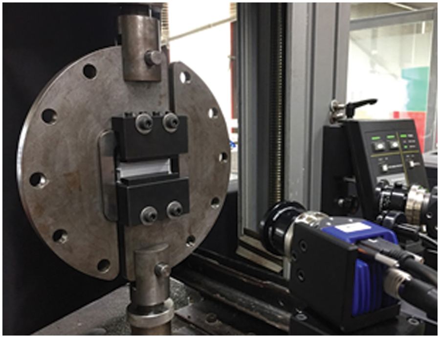
Figure 3: Modified-Arcan test [7]
The modified Arcan fixture was designed to induce a different state of stress within an adhesive layer by varying its angle. A direction of 0° and 90° represents a triaxial and pure shear mode. A direction of 30° and 60° induces a mixed state of stress, which is a tensile-shear mode in an adhesive joint. A direction of 120° represents a compressive-shear mode. The experimental yield and failure surfaces are plotted on the von Mises stress-hydrostatic pressure axis as shown in Fig. 4. They both depend on hydrostatic pressure with the non-linearity that corresponds to the exponential Drucker-Prager model. The elastic properties and yield surface parameters are summarized in Tables 1 and 2, respectively.
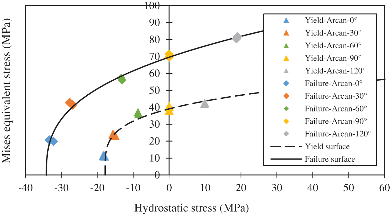
Figure 4: The Drucker-Prager yield and failure surface [7]


The parameters of the nonlinear hardening equation (Eq. (23)) were identified using simulations of the entire modified Arcan fixture to consider the deflection of the fixture. They are summarized in Table 3.

4 Finite Element Implementations
The exponential Drucker-Prager model with an associated flow rule was implemented in ABAQUS software via a user subroutine, UMAT. With this developed model, the high-order exponential Drucker-Prager is also possible. It also provides higher simulation stability at high-order exponential and requires fewer model parameters since the yield and plastic potential function are the same (associated flow). In subroutine UMAT, elastic and plastic behavior have to be established from input data (material properties). For elastic behavior, it is the same as in ABAQUS. Concerning plastic behavior, an iterative calculation approach is needed to find the solution of a stress tensor increment for plastic behavior (
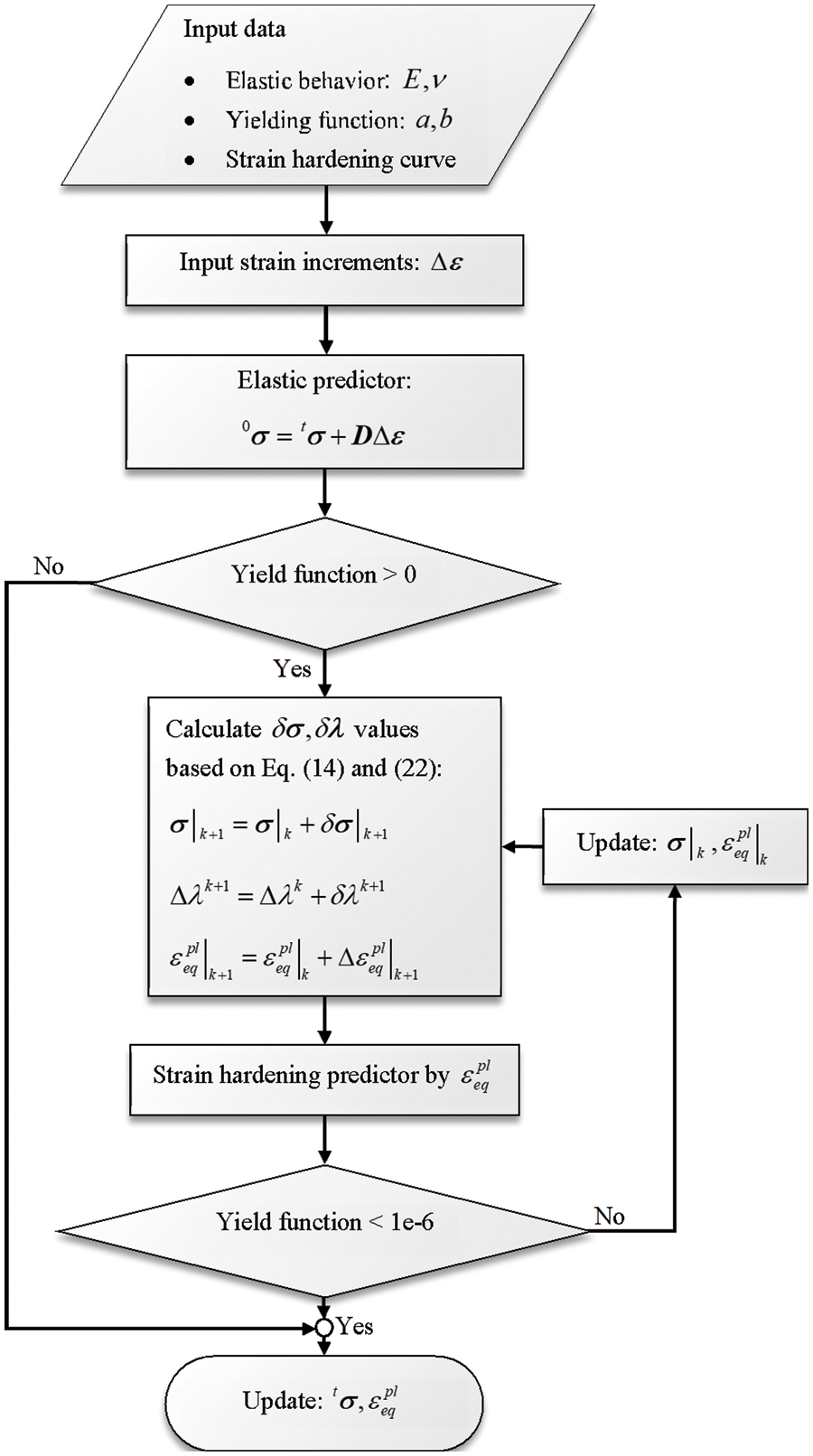
Figure 5: Flow chart of user subroutine UMAT
The finite element simulations of the modified Arcan test have been carried out as a validation of the implemented Drucker-Prager model. The four cases were performed: (1) an ABAQUS material model with 2nd order exponential Drucker-Prager yield function and non-associated flow rule (Eq. (4)); (2) a developed user subroutine UMAT with 2nd order exponential Drucker-Prager yield function and associated flow rule; (3) an ABAQUS material model with 4th order exponential Drucker-Prager yield function and non-associated flow rule (Eq. (4)), and (4) a developed user subroutine UMAT with 4th order exponential Drucker-Prager yield function and associated flow rule. The 4th order in the cases was selected because this high order fits relatively well the experimental data of the initial yield surface (Fig. 6). All mechanical properties for the simulations are summarized in Tables 1 to 5.
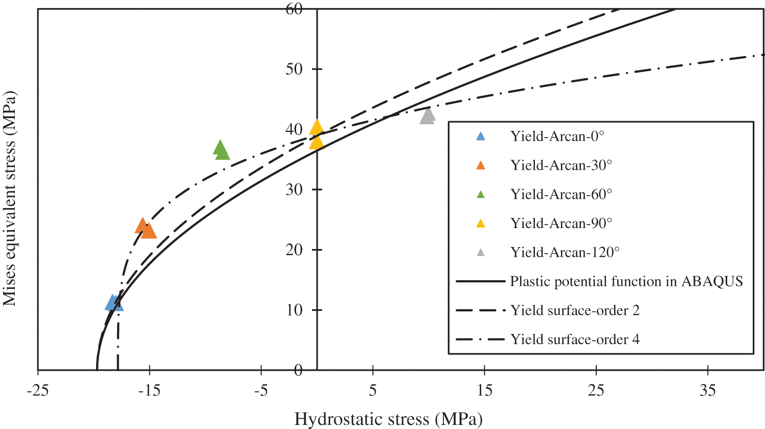
Figure 6: The plastic potential function


The modified Arcan fixture and adherends are made of steel (Young’s modulus = 200 GPa, Poisson’s ratio = 0.3 and yield stress = 570 MPa). The detailed geometries and boundary conditions are presented in Fig. 7. The adhesive layer has a thickness of 0.3 mm with a total cross-sectional area of 70 × 10 mm2. Because the modified-Arcan fixture is symmetrical in the x-y plane, the finite element model was only constructed in half, and the fixed boundary condition in the z-direction (U3 = 0) across the entire surface is applied. The tie condition is used for the constraint between the fixture and the adhesive layer. The model has 97,860 elements in total, with 350 elements for the adhesive layer. The element volume ranges from 0.3 to 15.5 mm3 and is kept constant at 0.3 mm3 for the adhesive layer. All fixture components, including an adhesive layer, were assigned a 3D 8-node solid element (C3D8) as shown in Fig. 8.
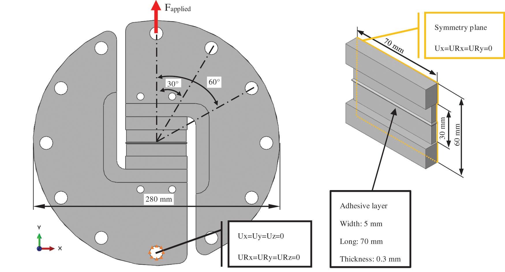
Figure 7: The detailed geometries and boundary conditions
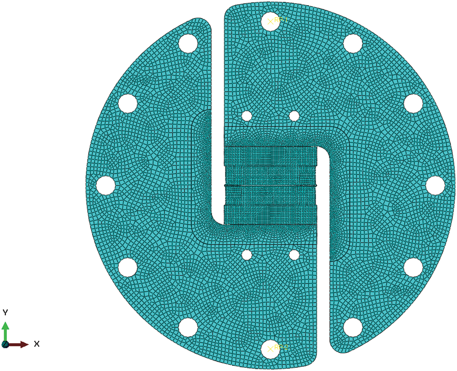
Figure 8: The element size of the modified Arcan test in direction 0°
The results of stress field on a modified Arcan fixture loaded in directions of 0°, 60°, 90°, and 120° are shown in Fig. 9. The deformations of the fixture are also comparable to the experimental test and cannot be neglected. This confirms the necessity of the entire fixture simulation.

Figure 9: The modified Arcan simulation in direction: (a) 0°, (b) 60°, (c) 90°, and (d) 120°
The comparison between experiments and simulations is shown in Fig. 10 for directions of 0°, 60°, 90°, and 120°, respectively. They are the plots of average stress and average strain as the stress-strain fields from a modified Arcan test are not uniform across the section. The simulation results for directions of 0°, 60°, and 90° from cases 1 and 2 are in good agreement with experimental results, while in cases 3 and 4, the discrepancy is more obvious. However, none of the cases can reproduce the results in the direction of 120°. Considering the comparisons with ABAQUS, these confirm the validity of the developed user subroutine UMAT. They also show that the epoxy-based adhesive SikaPower-497 behavior is compatible with the 2nd order exponential Drucker-Prager model.
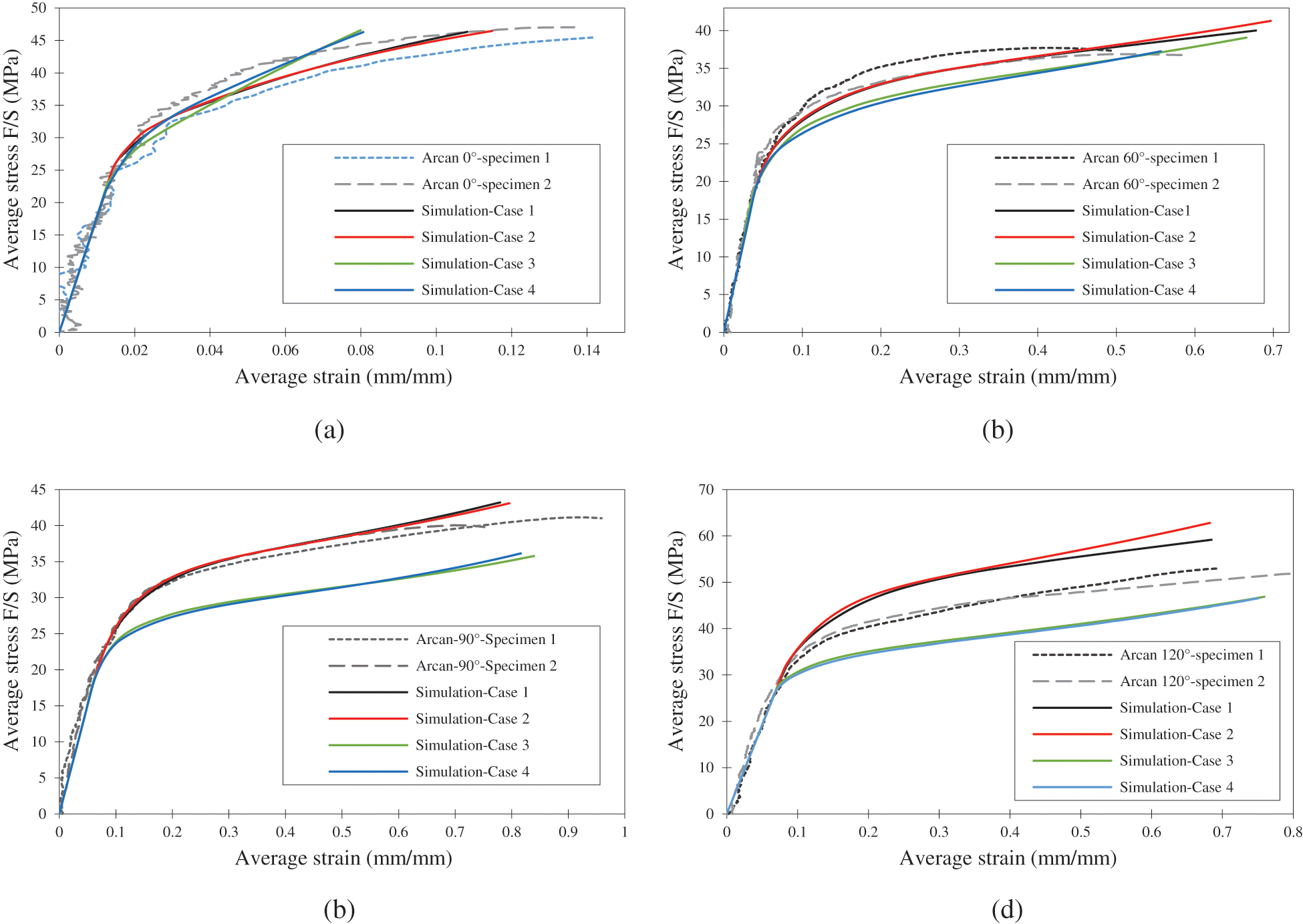
Figure 10: The modified Arcan simulation result in direction: (a) 0°, (b) 60°, (c) 90°, and (d) 120°
From the simulations, the ABAQUS material models with 2nd and 4th order exponential Drucker-Prager yield function and non-associated flow rule give almost identical results as the developed UMAT with 2nd and 4th order exponential Drucker-Prager yield function and associated flow rule. For further investigation, higher order exponential model simulations were performed for 120° loading. At the 9th order of exponential function (Fig. 11), the result does not converge for the ABAQUS material model. However, with the developed user subroutine UMAT, a converged result can be obtained despite a long computational time. This implies that the associated flow provides more numerical stability than the non-associated flow, especially for a very high order of exponential function and at highly positive hydrostatic pressure loads. In common application, there is no significant difference between the associated and non-associated. However, the associated flow still has the advantage of having fewer material parameters since it uses the same function to describe the yield surface and plastic potential function.
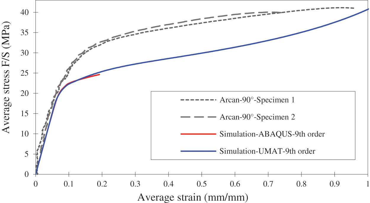
Figure 11: The simulation result of 9th order exponential model
The finite element implementation of the exponential Drucker-Prager model for the elastoplastic material has been carried out and validated experimentally with epoxy-based adhesive joints. The numerical implementation of the ABAQUS software was accomplished using a user subroutine, UMAT. This subroutine defines the plastic behavior of the adhesive joint using a yield and plastic potential function. With an associated flow, these functions are identical, providing the advantages of fewer plastic flow parameters and better numerical stability at very high orders of exponential function compared to when a non-associated flow is used. The developed UMAT is also capable of simulating high order exponential function of the Drucker-Prager model which makes it more flexible to apply to other elastoplastic materials.
For the adhesives used in this study (SikaPower-497), its hydrostatic pressure dependent yield surface and plastic behavior have been identified using the modified Arcan tests. The experimental results from different directions of the modified Arcan fixture are used as a validation for the developed UMAT. The simulation result from the 2nd order exponential Drucker-Prager model shows a good agreement with experiments. For the 4th order exponential Drucker-Prager model, it predicts an initial yield surface better than the 2nd order model but poorly interprets the plastic deformation of the adhesive. Concerning the results at direction 120°, neither the ABAQUS material model nor the developed user subroutine UMAT can reproduce the experimental results. This divergence is also expected since the experimental results at direction 120° show the mix of cohesive and adhesive failure modes. In this direction, the compressive stress induced by the fixture strengthens the adhesive joint, so its strength is close to the interface strength leading to the mixed failure mode. The interface element option in ABAQUS [14–16] was not used in this work since the developed UMAT focuses only on material behavior. This limitation opens the way to further development of this UMAT. Another important factor that affects the simulation results is the hardening rule [17–19]. Its parameters can also be further investigated based on hydrostatic pressure and effective plastic strain to provide better simulation results.
Funding Statement: This research was funded by King Mongkut’s University of Technology North Bangkok. Contract No. KMUTNB-PHD-62-07.
Conflicts of Interest: The authors declare that they have no conflicts of interest to report regarding the present study.
References
1. Chiminelli, A., Breto, R., Jiménez, M. A., Velasco, F., Abenojar, J. et al. (2016). Experimental method for the determination of material parameters of plasticity models for toughened adhesives. International Journal of Adhesion and Adhesives, 68(2), 182–187. DOI 10.1016/j.ijadhadh.2016.03.004. [Google Scholar] [CrossRef]
2. Yang, Y., Gong, M., Xia, X., Wu, L. (2022). Experimental and numerical study on mechanical properties of Z-pins reinforced composites adhesively bonded single-lap joints. Computer Modeling in Engineering & Sciences, 131(1), 365–378. DOI 10.32604/cmes.2022.018535. [Google Scholar] [CrossRef]
3. Özer, H., Öz, Ö (2017). The use of the exponential Drucker-Prager material model for defining the failure loads of the mono and bi-adhesive joints. International Journal of Adhesion and Adhesives, 76(21), 17–29. DOI 10.1016/j.ijadhadh.2017.02.005. [Google Scholar] [CrossRef]
4. Richmond, O., Spitzig, W. A. (1980). Pressure dependence and dilatancy of plastic flow. Proceedings of the 15th International Congress of Theoretical and Applied Mechanics, pp. 377–386. Toronto, Canada. [Google Scholar]
5. Drucker, D. C., Prager, W. (1952). Soil mechanics and plastic analysis for limit design. Quarterly of Applied Mathematics, 10(2), 157–165. DOI 10.1090/qam/48291. [Google Scholar] [CrossRef]
6. Yu, X. X., Crocombe, A. D., Richardson, G. (2001). Material modelling for rate-dependent adhesives. International Journal of Adhesion and Adhesives, 21(3), 197–210. DOI 10.1016/S0143-7496(00)00051-8. [Google Scholar] [CrossRef]
7. Suwanpakpraek, K., Patamaprohm, B., Phongphinittana, E., Chaikittiratana, A. (2020). Experimental investigation and finite element modelling of the influence of hydrostatic pressure on adhesive joint failure. Materials Science and Engineering, 886(1), 012052. [Google Scholar]
8. Patamaprohm, B., Phongphinittana, E., Guinault, C., Gantchenko, V., Renard, J. et al. (2016). Study of adhesive joints under static and fatigue loading. Revue des composites et des matériaux avancés, 26(1), 1–23. [Google Scholar]
9. Cognard, J. Y., Davies, P., Sohier, L., Créac’hcadec, R. (2006). A study of the non-linear behavior of adhesively-bonded composite assemblies. Composite Structures, 76(1–2), 34–46. DOI 10.1016/j.compstruct.2006.06.006. [Google Scholar] [CrossRef]
10. Safaei, M., Yoon, J. W., de Waele, W. (2014). Study on the definition of equivalent plastic strain under non-associated flow rule for finite element formulation. International Journal of Plasticity, 58, 219–238. DOI 10.1016/j.ijplas.2013.09.010. [Google Scholar] [CrossRef]
11. Dassault Systems (2016). ABAQUS 2016: Theory manual. Dassault Systems. Rhode Island,USA. [Google Scholar]
12. Ortiz, M., Popov, E. P. (1985). Accuracy and stability of integration algorithms for elastoplastic constitutive relations. International Journal for Numerical Methods in Engineering, 21, 1561–1576. DOI 10.1002/(ISSN)1097-0207. [Google Scholar] [CrossRef]
13. Liu, K., Chen, S. L. (2017). Finite element implementation of strain-hardening Drucker-Prager plasticity model with application to tunnel excavation. Underground Space, 2(3), 168–174. DOI 10.1016/j.undsp.2017.08.003. [Google Scholar] [CrossRef]
14. Jousset, P., Rachik, M. (2014). Implementation, identification and validation of an elasto-plastic-damage model for the finite element simulation of structural bonded joints. International Journal of Adhesion and Adhesives, 50, 107–118. DOI 10.1016/j.ijadhadh.2014.01.020. [Google Scholar] [CrossRef]
15. Ren, B., Li, S. (2014). Multiscale modeling and prediction of bonded joint failure by using an adhesive process zone model. Theoretical and Applied Fracture Mechanics, 72(2), 76–88. DOI 10.1016/j.tafmec.2014.04.007. [Google Scholar] [CrossRef]
16. Li, Z., Ji, J., Vu-Quoc, L., Izzuddin, A., Zhuo, B. et al. (2021). A 3-node co-rotational triangular finite element for non-smooth, folded and multi-shell laminated composite structures. Computer Modeling in Engineering & Sciences, 129(2), 485–518. DOI 10.32604/cmes.2021.016050. [Google Scholar] [CrossRef]
17. Lu, D., Su, C., Zhou, X., Wang, G., Du, X. (2022). A cohesion-friction combined hardening plastic model of concrete with the nonorthogonal flow rule: Theory and numerical implementation. Construction and Building Materials, 325(11), 126586. DOI 10.1016/j.conbuildmat.2022.126586. [Google Scholar] [CrossRef]
18. Hou, Y., Min, J., Stoughton, T. B., Lin, J., Carsley, J. E. et al. (2020). A non-quadratic pressure-sensitive constitutive model under non-associated flow rule with anisotropic hardening: Modeling and validation. International Journal of Plasticity, 135(1), 102808. DOI 10.1016/j.ijplas.2020.102808. [Google Scholar] [CrossRef]
19. Mohapatra, P. C., Smith, L. V. (2021). Adhesive hardening and plasticity in bonded joints. International Journal of Adhesion and Adhesives, 106, 102821. DOI 10.1016/j.ijadhadh.2021.102821. [Google Scholar] [CrossRef]
Cite This Article
 Copyright © 2023 The Author(s). Published by Tech Science Press.
This work is licensed under a Creative Commons Attribution 4.0 International License , which permits unrestricted use, distribution, and reproduction in any medium, provided the original work is properly cited.


 Submit a Paper
 Propose a Special lssue
 View Full Text
 Download PDF
 Downloads
 Citation Tools