 Open Access
REVIEW
A Review of Electromagnetic Energy Regenerative Suspension System & Key Technologies
School of Transmission and Vehicle Engineer, Shandong University of Technology, Zibo, 255000, China
* Corresponding Author: Jiayu Lu. Email:
Computer Modeling in Engineering & Sciences 2023, 135(3), 1779-1824. https://doi.org/10.32604/cmes.2022.023092
Received 09 April 2022; Accepted 07 July 2022; Issue published 23 November 2022
Abstract
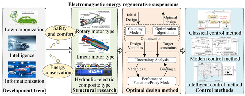
The active suspension has undoubtedly improved the performance of the vehicle, however, the trend of “lowcarbonization, intelligence, and informationization” in the automotive industry has put forward higher and more urgent requirements for the suspension system. The automotive industry and researchers favor active energy regeneration suspension technology with safety, comfort, and high energy regenerative efficiency. In this paper, we review the research progress of the structure form, optimization method, and control strategy of electromagnetic energy regenerative suspension. Specifically, comparing the pros and cons of the existing technology in solving the contradiction between dynamic performance and energy regeneration. In addition, the development trend of electromagnetic energy regenerative suspension in the field of structure form, optimization method, and control technology prospects.Graphic Abstract
Keywords
According to 2020 statistics from the International Energy Agency (IEA), the transport sector accounts for 26% of global carbon emissions [1]. Among them, automobiles are an important emission source in the field of transportation. Therefore, energy regenerative and low-carbon technology is in line with the development theme of green transformation of the world automotive industry and is also a strategic need to implement China’s “double carbon” goal [2].
As the automotive industry develops in the direction of “low-carbonization, intelligence, and informationization” [3]. The traditional chassis can no longer meet the future development needs of intelligent electric vehicles, and the suspension system is undergoing technological innovation as a key part of the automotive chassis. The active suspension system can realize dynamic adaptive adjustment according to driving conditions and road excitation so that the suspension system is always in the best damping working condition to ensure the driving stability and comfort of the driver and passengers. At present, electromagnetic, air, and hydraulic active suspension technology has become mature, and its improvement in vehicle performance is undoubted [4]. But the performance improvement requires additional energy consumption, which is not conducive to the improvement of the overall energy efficiency of the vehicle. However, in the study of vehicle energy distribution, researchers found that, as shown in Fig. 1, the vibration energy recovery technology can reduce the energy consumption of the vehicle by 7%–10%, make up for the energy consumption of the active suspension, and improve the utilization efficiency of the vehicle power source to achieve the purpose of energy-saving and emission reduction [5,6].
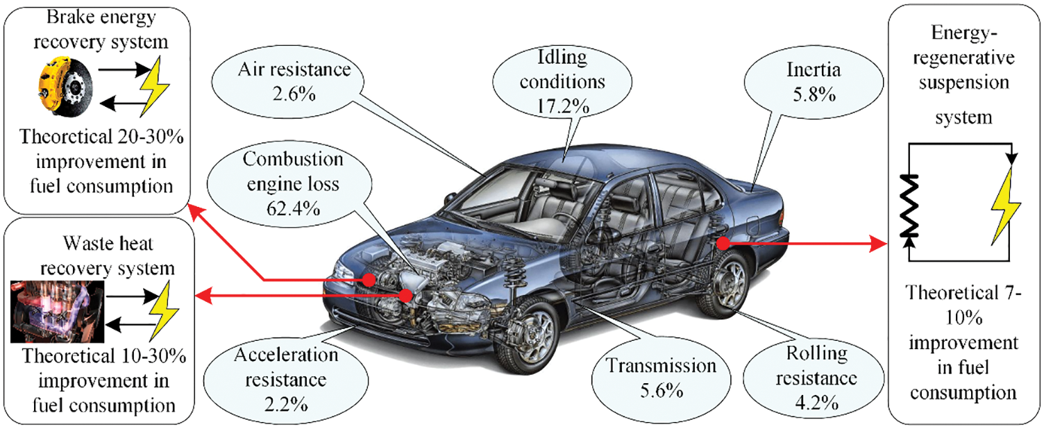
Figure 1: Energy consumption and energy-harvesting potential
The energy regenerative process of the existing air-type and hydraulic-type active suspensions is relatively complicated: the vibration energy needs to be converted into internal energy, and then converted into electrical energy using a motor [7,8]. Both of them need to add subsidiary institutions, which increases the difficulty of control and lowers the energy conversion efficiency [9]. The electromagnetic suspension uses current as the working medium to facilitate linear control. At the same time, according to the characteristics of the motor itself, the vibration energy can be directly converted into electrical energy, which has the characteristics of compact structure, and high energy regenerative efficiency [10]. Therefore, the electromagnetic energy regenerative suspension system, which considers the characteristics of active dynamic performance and energy regeneration, meets the development needs of future chassis and gradually becomes a hot spot for scholars from various countries to study.
This paper reviews the latest advances in dynamic performance and energy harvesting of electromagnetic energy regenerative suspensions. The main purpose of the research is to explore the structural form of the electromagnetic energy regenerative suspension according to the recovery effect of the suspension system on the vibration energy and the dynamic performance. On this basis, the multidisciplinary optimization design method of electromagnetic energy regenerative suspension system is further analyzed. In addition, the coordination of various control methods in the performance of electromagnetic energy regenerative suspension systems is discussed. And the existing problems and future development trends of the current electromagnetic energy regenerative suspension system and its key technologies are discussed, which will help to expand the development of the electromagnetic energy regenerative suspension optimization design method and control theory.
2 Structural Research of Electromagnetic Energy Regenerative Suspensions
In the late 1980s, Karnopp verified the feasibility of combining permanent magnet motors with automotive suspension systems through theoretical analysis [11]. With the development of permanent magnet materials and electronic control technology, electromagnetic energy regenerative suspension has gradually attracted the research interest of scholars from all over the world. At present, there are various forms of mainstream electromagnetic energy regenerative suspensions. The different structural solutions of electromagnetic energy regenerative suspensions can be divided into three categories: rotary motor energy regenerative suspensions, linear motor energy regenerative suspensions, and hydraulic-electric composite energy regenerative suspensions.
2.1 Rotary Motor Electromagnetic Energy Regenerative Suspensions
The rotating electromagnetic energy regenerative suspension generally consists of a set of motion conversion mechanisms and a rotating motor [12]. The development of the rotating motor is relatively mature, and has the remarkable characteristics of small quality and high reliability; the motion conversion mechanism converts the reciprocating motion of the suspension into the rotating motion of the motor, and the vibration energy can be converted into electrical energy by using the characteristics of the rotating motor yitself. According to the different forms of motion conversion mechanisms, rotary energy regenerative suspensions are divided into three categories: ball-screw type, rack-pinion type, and rocker-arm type.
2.1.1 Ball-Screw Type Electromagnetic Energy Regenerative Suspensions
The ball-screw mechanism has the advantages of high efficiency, smooth motion, and accurate positioning, and can realize the mutual transformation of linear motion and rotary motion, which is now applied to the rotary electromagnetic energy regenerative suspension system.
The rotary electromagnetic energy regenerative suspension is easy to cause problems such as large fluctuation of electromagnetic output force and overload operation of the motor due to the addition of a motion conversion mechanism. Therefore, stability and safety are the first key issues to be considered in the design process of electromagnetic energy regenerative suspensions. Bose Corporation uses dual motors combined with ball-screws in a symmetrical arrangement, as shown in Fig. 2a. To ensure that the output forces are equal in size and opposite in direction, reducing the impact of electromagnetic force fluctuations on the rotating electromagnetic energy regenerative suspension [13]. The electromagnetic energy regenerative suspension system designed by Xie et al. [14] is shown in Fig. 3. The stator of the generator has 12 independently controlled slot windings, which can generate different electromagnetic damping by controlling the number of generator switches and adjusting the external resistance to ensure the stable output of electromagnetic force in real-time. ZF and Volkswagen Group jointly developed the upper and lower spring arrangement of the electromagnetic energy regenerative suspension, as shown in Fig. 2b, to avoid excessive inertial shocks damaging the suspension system [15]. The Schaeffler Group has designed an electromagnetic energy regenerative suspension using a combination of brushless DC motor and ball-screw solution, as shown in Fig. 2c. The centrifugal brake inside the electromagnetic actuator can effectively reduce the motor speed and avoid the overload operation of the motor [16].
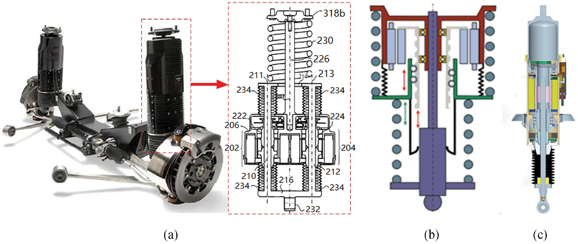
Figure 2: (a) Bose suspension system; (b) Bose suspension system; (c) Schaeffler “electromagnetic energy regenerative suspension mechanism”
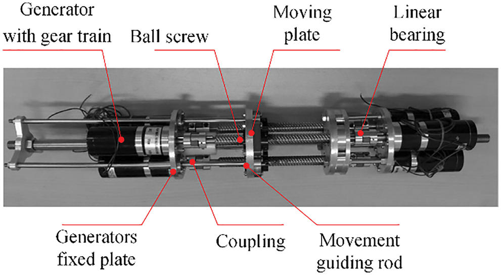
Figure 3: Prototype of the energy regenerative suspension mechanism
The working efficiency of the rotary electromagnetic energy regenerative suspension cannot be ignored. Zhao et al. [17] proposed the method of changing the charging voltage in segments to convert the vibration energy into electrical energy through the motor and input it directly into the battery pack; by reducing the charging voltage of the battery pack, the problem that the excitation speed is small and the recycling voltage is too small to be charged is solved. Zuo et al. [18] designed a new integrated mechanical motion rectifier in the electromagnetic energy regenerative suspension with the structure shown in Fig. 4b, which always ensures the conversion of reciprocating suspension vibration into unidirectional rotational motion of the motor, reduces the gear shock caused by external oscillation, ensures that the generator rotates at a relatively stable speed during irregular vibration, and significantly improves the energy regenerative characteristics of the electromagnetic energy regenerative suspension. In the performance test on Ford F250, as shown in Fig. 4a, when the vehicle is driving on the road at a speed of 40 miles per hour, the energy regenerative suspension can reduce the RMS value of the ground acceleration by 11.12% in a period of 8 s, the average power harvested by the quarter electromagnetic energy regenerative suspension system is 13.3 W [19].
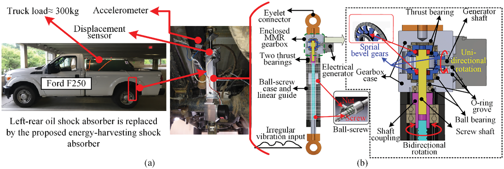
Figure 4: A mechanical-motion-rectifier-based energy regenerative; (a) Setup of field tests; (b) Prototype and working principle
Due to the limited installation space of the rotary electromagnetic energy regenerative suspension system, there is a conflicting relationship between its structural size and its working performance. Galluzzi et al. [20] proposed an integrated design method of electromechanical parameters, which integrates the rotating motor and the suspension design. As shown in Fig. 5a, the overall quality of the parallel design of the electrical terminals of the motor and the resistive load is reduced by 12% compared with previous similar studies. However, when the voltage regulator is not connected in parallel with the electromagnetic load, the energy regenerative suspension has a damped failure zone proportional to the battery voltage, and the constant output voltage regulator has fluctuations in the damping coefficient. Li et al. [21,22] designed a new type of undamped failure energy regenerative suspension, as shown in Fig. 5b, to eliminate damping fluctuations and damping failure zones. Zhang et al. [23] adopted a single ball-screw mechanism and carried out a modular design of the energy regenerative suspension from the perspective of the operation stability, flexibility, and energy application of the electromagnetic energy regenerative suspension, which is divided into vibration input module, transmission module, and generator module as shown in Fig. 6a. The working principle is as follows: the suspension vibration caused by road excitation is transmitted to the vibration input module; the reciprocating vibration is converted into the rotary motion required for the motor work by the transmission module, and the ball-screw mechanism, as the core component of the transmission module, can generate the corresponding damping by different pitches to improve the comfort of the vehicle; the electrical energy can be generated by the generator module. Based on this, Zhang et al. [24] tried to replace the single ball-screw in the original transmission module with a pair of ball-screw, as shown in Fig. 6b. An electrical energy storage module was added, and the electrical energy generated by the generator was stored in a supercapacitor, thus extending the driving range of the electric vehicle, which can extend the driving range by approximately 1 mile per 100 miles when the electric vehicle is driven at 60 km/h on Class B roads.
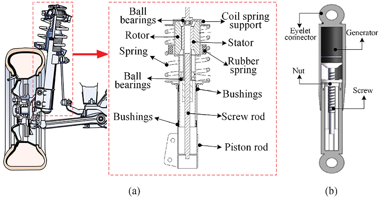
Figure 5: (a) Electromagnetic energy regenerative suspension mechanism integrated into a McPherson suspension and cross-section of the mechanism; (b) Energy regenerative suspension mechanism
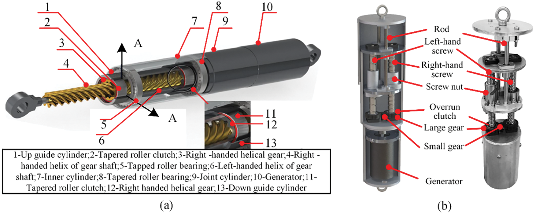
Figure 6: (a) Details of the energy regenerative suspension mechanism section A-A; (b) Structure of the energy regenerative suspension mechanism
According to the in-depth research of ball-screw type energy regenerative suspension by the above scholars, the ball-screw type energy regenerative suspension system has the advantages of good reliability, high transmission efficiency and compact structure, but the internal clearance between the mechanical mechanism is easy to cause its damping performance to be attenuated under the condition of the high road excitation frequency.
2.1.2 Rack-Pinion Type Electromagnetic Energy Regenerative Suspensions
The rack-pinion mechanism has many advantages such as simple structure, high transmission efficiency, and conversion between circular motion and unidirectional motion, etc. It is now widely used in rotary electromagnetic energy regenerative suspension systems.
Since the 1990s, foreign scholars have begun to research the energy regenerative suspension based on the rack-pinion mechanism. Suda et al. [25] pioneered the design of an electromagnetic energy regenerative suspension based on a rack and pinion mechanism that achieves good dynamic performance and ensures low energy consumption. Beno et al. [26] and the U.S. Department of Defense jointly developed a rack-pinion electromagnetic energy regenerative suspension named UT-CEMAS for military vehicles. The schematic diagram is shown in Fig. 7a. Road tests have shown that the electromagnetic energy regenerative suspension has improved off-road performance, but there is still room for improvement in regenerative [27]. After verifying the feasibility of the rack-pinion energy regenerative suspension, researchers conducted in-depth research on the coordination between its reliability, energy regenerative performance, and functions.
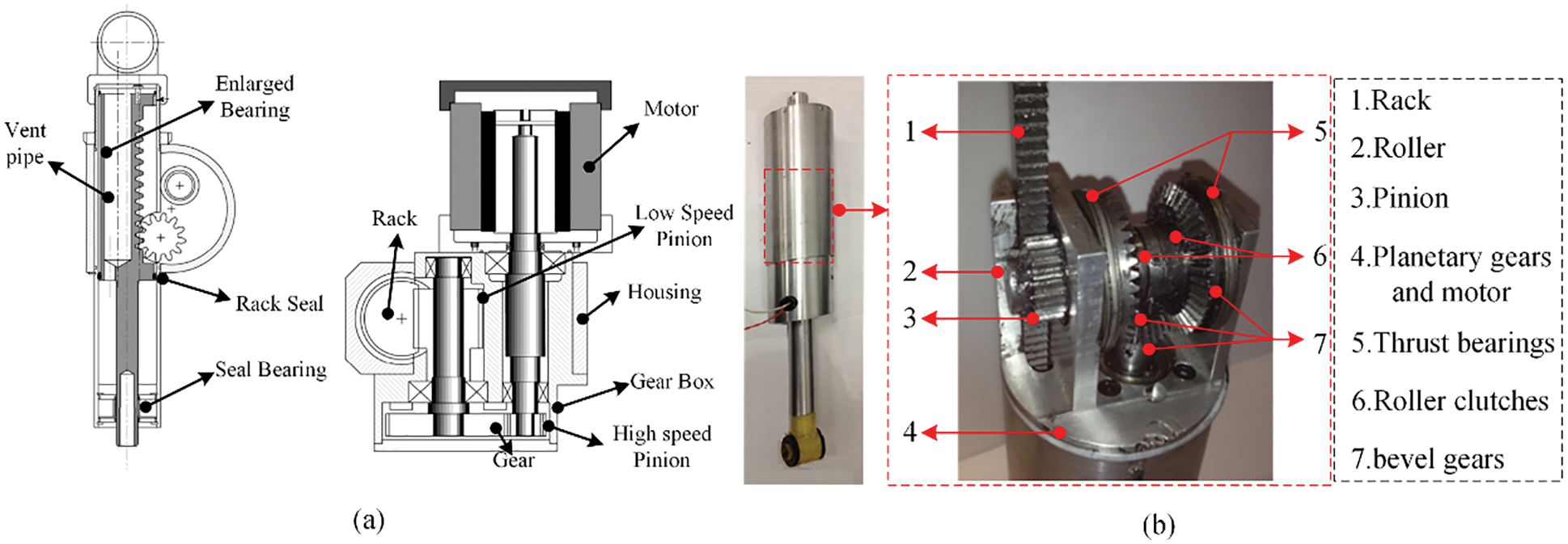
Figure 7: (a) Rack and pinion type electromagnetic energy regenerative suspension mechanism; (b) Actual prototype and inner structure
The rack and pinion mechanism are the core component of the electromagnetic energy regenerative suspension, and its reliability will directly affect the driving safety of the vehicle. Papageorgiou [28] was the first to test the mechanical properties of the developed rack-pinion suspension, and its theoretical damping matched the actual damping when the effect of nonlinear factors was eliminated. Zuo et al. [29–31] achieved variable damping coefficients and asymmetry of vibration and rebound motion by controlling the electrical loading of the electromagnetic energy regenerative suspension, as shown in Fig. 7b; using rollers to guide the preload on the gear carrier and gear transmission to reduce tooth clearance and friction and improve the reliability of the system. Zhang et al. [32,33] developed a modular design for the energy regenerative suspension, as shown in Fig. 8a, which is divided into a vibration energy harvesting module, a motion conversion module, a power generation module, and an electrical energy storage module. The motion conversion module can steadily output the asymmetric compression/extension damping force required by the suspension system. Based on this, Zhang et al. [34] used a tree mechanism architecture for the design of the energy regenerative suspension, as shown in Fig. 8b. The motion conversion mechanism consists of two helical racks with opposite threads, which further improves the reliability of the system. Guo [35] designed an electromagnetic energy regenerative suspension based on a rack-and-pinion mechanism for a heavy-duty vehicle. The system only uses a single pinion shaft drive and is equipped with a mechanical rectifier bridge, which improves the durability of the drive system, reduces energy loss, and improves energy regenerative efficiency. To further improve its energy regenerative efficiency as well as the reliability of the system operation, the electromagnetic energy regenerative suspension designed by Wang et al. [36] effectively alleviated the outstanding contradiction between vibration control and energy recovery.
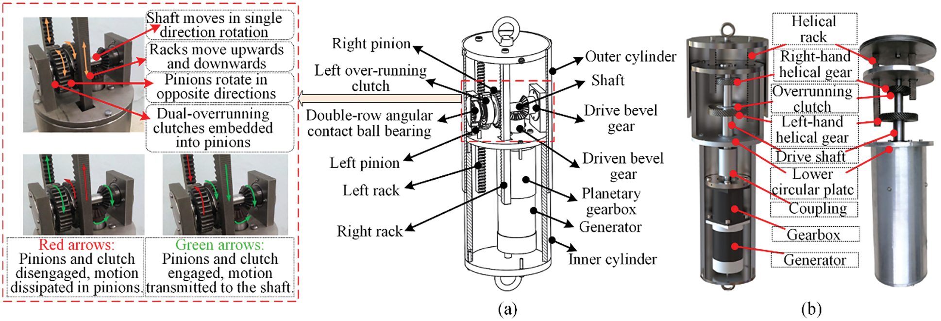
Figure 8: (a) Detailed marks of all of the parts; (b) Structure of the energy regenerative suspension mechanism
The rack-pinion energy regenerative suspension has high transmission precision and good stability, but when the road impact is too large, the rack-pinion mechanism is easy to break, which affects the driving safety of the vehicle.
2.1.3 Rocker-Arm Type Electromagnetic Energy Regenerative Suspensions
Compared with the ball-screw type and the rack-pinion type, the rotary motor combined with the rocker type electromagnetic energy regenerative suspension system has smaller inertia and faster response speed, but it is more difficult to install and more difficult to control.
The rocker-arm type electromagnetic energy regenerative suspension designed by Chen et al. [37,38] can satisfy the ride comfort and safety of the vehicle. Jonasson et al. [39] at the Royal Institute of Technology in Sweden, in conjunction with Volvo, have studied an electromagnetic energy regenerative suspension based on a rocker mechanism with a dual-motor design that broadens the operating bandwidth of the electromagnetic energy regenerative suspension. Audi et al. [40–42] announced a new electromagnetic energy regenerative suspension technology in 2016, which is named “eROT”. As shown in Fig. 9, the electromagnetic energy regenerative suspension consists of an alternator, a gear unit, a fixed connection, and a rocker-arm. The gear unit and the rocker-arm mechanism cooperate to be responsible for deceleration and torque increase or speed increase and torque decrease to meet the dynamic performance and energy regenerative performance of the suspension. When the vehicle is excited by the uneven road, the average energy regenerative of each suspension motor is 100–150 W. And the system can reduce CO2 emissions by up to 3 grams per kilometer in daily driving conditions. Considering the limitation of installation space, scholars from all over the world have little research on rocker-arm electromagnetic energy regenerative suspension. With the continuous development of the automobile industry, the changes in the layout of the automobile chassis will promote the further development of the rocker-arm type electromagnetic energy regenerative suspension.
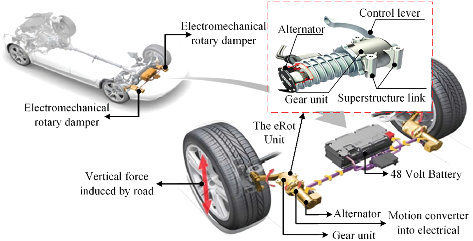
Figure 9: The innovative “eROT” based on a horizontally arranged electromechanical rotary suspension mechanism
The rotating motor type energy regenerative suspension has been widely studied because of the reliability of the motion conversion mechanism and the high efficiency of the rotating motor. The simulation and test results in Table 1 show that its damping effect and energy regenerative effect is significant. However, the energy regenerative suspension structure is mainly completed by a mechanical mechanism, and problems such as component wear and structure noise cannot be ignored. It requires regular maintenance and increases additional costs.

2.2 Linear Motor Electromagnetic Energy Regenerative Suspensions
The linear motor is the core component of the electromagnetic energy regenerative suspension, and its performance directly affects the dynamic performance and energy regenerative performance of the electromagnetic energy regenerative suspension [43]. Compared with the rotary motor, its structure is more versatile, with the advantages of fast response, high efficiency, high power density, etc. The linear-motors are now widely used in the field of industrial automation and drive systems, such as Siemens, Bosch’s precision machines, Inductrack suspension systems, etc. [44,45]. The cylindrical linear motor has the same reciprocating linear motion as the motion stroke of the suspension, and it is used as the actuator of the active suspension to output the main power to suppress the vibration of the body. Under random pavement excitation, the relative motion of the coil and the permanent magnet causes a change in the magnetic flux in the induction coil, and according to Faraday’s law of electromagnetic induction, the vibration energy can be converted into electrical energy.
Okada et al. [46] designed an electromagnetic energy regenerative suspension based on a permanent magnet synchronous motor, which can realize the energy regenerative function at high-speed motion and generate adapted electromagnetic damping to ensure the damping performance at low-speed motion. Wang et al. [47] investigated the topology of different tubular linear motors and found that the regenerative suspension designed based on quasi-Halbach array kinematic linear motors has superior controllability bandwidth, as shown in Fig. 10a. The vehicle has improved smoothness, comfort, safety, and maneuverability. Gysen et al. [48,49] proposed a general harmonic modeling method to calculate the three-dimensional magnetic field distribution of the Halbach array based on electromagnetic energy regenerative suspension and conducted in-depth research on the topology and performance of electromagnetic energy regenerative suspension. They analyzed the efficiency of the electromagnetic energy regenerative suspension and determined the synergistic relationship between the losses, output power, and input current of the electromagnetic energy regenerative suspension under comfort and safety [50]. Based on this research, Gysen et al. [51] jointly developed a prototype electromagnetic energy regenerative suspension system with SKF and BMW of Sweden. As shown in Fig. 10b. To further improve the magnetic flux density inside the linear motor to improve the overall performance of the electromagnetic energy regenerative suspension system. Eckert et al. [52,53] designed a two-layer Halbach array of tubular linear motors integrated with the suspension system, as shown in Fig. 11a. To avoid the continuous power supply of the electromagnetic suspension system, Ye et al. [54] adopted a direct-drive electromagnetic active suspension system designed in parallel with a tubular linear motor with a double-layer Halbach array and a coil spring. The spring can support the sprung mass, as shown in Fig. 11b. The hollow topology has a good dynamic response, servo characteristics, and a small force fluctuation rate.

Figure 10: (a) Linear electromagnetic actuator based active vehicle suspension unit; (b) Prototype of the electromagnetic active suspension system for a BMW 530i together with the wheel hub
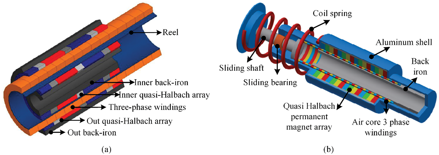
Figure 11: (a) Linear tubular moving-coil actuator with a four-pole dual quasi-Halbach array; (b) The structure of a direct-drive electromagnetic active suspension system
The current research shows that Halbach arrays can generate ideal sinusoidal distributed magnetic fields inside electromagnetic linear actuators, and double-layer Halbach arrays can increase the internal magnetic flux density to ensure smooth electromagnetic force output and vibration energy conversion. However, the electromagnetic energy regenerative suspension has problems such as excessive mass, long displacement, and working dead zone in actual operation, and scholars from various countries have conducted corresponding research. To reduce the mass of the electromagnetic energy regenerative suspension system, the performance deterioration of the suspension system caused by excessive unsprung mass is avoided. Zuo et al. [55,56] designed a compact energy regenerative suspension based on a four-phase electromagnetic actuator. The working principle is shown in Fig. 12a. By using the alternating operation of the electromagnetic actuator in four operating quadrants, vibration energy recovery is achieved without loss of ride comfort. Lafarge et al. [57,58] designed and fabricated an embedded linear electromagnetic energy regenerative suspension structure, as shown in Fig. 12b, which avoided the problems caused by the volume and complexity of the electromagnetic energy regenerative suspension during the installation process. And to achieve the damping and energy regenerative functions without changing the initial structure of the suspension. Stribrsky et al. [59,60] used Copley Controls’ tubular permanent magnet linear motor TBX3810 to design an electromagnetic energy regenerative suspension and develop a test signal for simulating a real road to verify the feasibility that the electromagnetic energy regenerative suspension can be used to determine regenerative requirements based on road conditions and the vehicle’s energy storage state. Wang et al. [61] introduced a rectifier module and voltage regulator module in the energy regenerative circuit of electromagnetic energy regenerative suspension, and the transient one-way current generated by electromagnetic energy regenerative suspension was changed into a low-pulse DC power supply to charge the battery through the rectifier module and voltage regulator module. To avoid the “dead zone” of the electromagnetic energy regenerative suspension, Lai et al. [62] made the “dead zone” generating unit required by the driving circuit in the driving circuit of the linear motor, which improved the movement range of the electromagnetic energy regenerative suspension work efficiency.

Figure 12: (a) Diagram of the four-phase generator configuration: the coils move in the magnetic field during the vibration of the vehicle suspension mechanism; (b) The prototype embedded in the suspension mechanism
At present, scholars from various countries have carried out extensive and in-depth research on linear electromagnetic energy regenerative suspension. The simulation and test data are shown in Table 2. According to the data, it can be concluded that the linear electromagnetic energy regenerative suspension has no motion conversion structure, and the work efficiency is significantly improved; the motion trajectory matches the suspension stroke, which significantly improves the dynamic performance of the vehicle; the mechanical friction loss is small, and the system reliability is good.

2.3 Hydraulic-Electric Composite Electromagnetic Energy Regenerative Suspensions
In view of the fact that the rotary electromagnetic energy regenerative suspension adopts a mechanical mechanism for power transmission, the clearance of mechanical transmission is unavoidable, and the backlash seriously affects the reliability and durability of the energy recovery system. when received severe road impact will lead to gear cracking or even broken teeth. The hydraulic-electric composite design can effectively avoid such problems [63,64]. The hydraulic-electric energy regenerative suspension system, which integrates the hydraulic-electric mechanism and the suspension system, takes into account the flexibility of the hydraulic system layout and the effectiveness of the electromagnetic energy regenerative.
At the end of the 20th century, as PBW (Power-by-Wire) drive system came into people’s view [65]. The hydraulic-electric actuation technology attracted scholars to carry out research based on the hydraulic-electric composite suspension system, because of its high-power output and high reliability [66]. NISSAN has developed a hydraulic interconnection-based body attitude control system that can be used to adjust the body attitude [67]. Satoh et al. [68] proposed an initial design idea for a hydraulic energy regenerative suspension mechanism. Wendel et al. [69] added energy harvesting functions to the hydraulic active suspension system. In 2009, a research group at MIT developed a hydraulic-electric composite energy regenerative suspension structure, and later they founded the company Levant Power and developed an energy regenerative suspension mechanism called Gen-shock. The structure is shown in Fig. 13. The core of the electromagnetic energy regenerative shock absorber is a hydraulic system composed of a hydraulic cylinder, pipeline, one-way valve, accumulator, and hydraulic motor. They conducted road tests on vehicles such as military Humvees and heavy trucks, the result showed that they were able to save about 6% of the fuel and were 71% more durable than conventional passive suspensions [70,71].
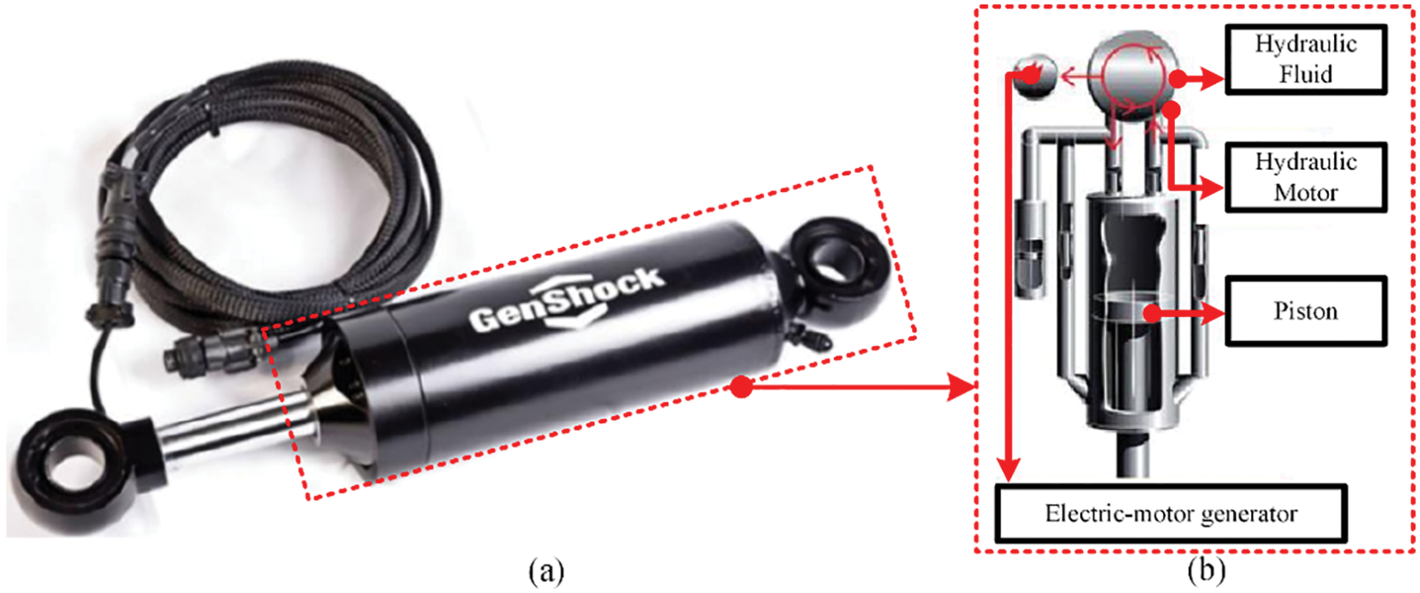
Figure 13: Gen-shock energy regenerative suspension mechanism and its working principle diagram
To further promote the development of hydraulic-electric hybrid actuator technology, reducing losses is of great significance for saving suspension energy, improving system reliability, and improving power conversion efficiency [72]. Chen et al. [73] designed a dual-chamber hydraulic energy regenerative suspension and analyzed its dynamics, but lacked a method to calculate the energy regenerative efficiency. Kou et al. [74] designed a new type of hydraulic-electric composite electromagnetic energy regenerative suspension, as shown in Fig. 14a. They carried out research on its dynamic performance and energy regenerative performance. Ding et al. [75] connected a mechanical speed change mechanism composed of a gear system and a one-way cutter in series between the hydraulic motor and the generator, which solved the problem of frequent commutation of the motor, but increased the weight and volume of the suspension system, and affect the energy regenerative efficiency. Xu et al. [76,77] designed a hydraulic rectifier bridge according to the working principle of the Wheatstone bridge, and realized a highly integrated design of the hydraulic-electric composite energy regenerative suspension system, as shown in Fig. 14b, which reduces the complexity of the energy harvesting module. Fang et al. [78,79] improved the hydraulic-electric composite energy regenerative suspension, using a low-pressure accumulator to replace the hydraulic oil tank, and the energy collection efficiency of the energy regenerative suspension was about 16.3%. Guo et al. [80,81] analyzed the relationship between hydraulic-electric composite energy regenerative suspension and vehicle fuel consumption. The hydraulic-electric composite energy regenerative suspension significantly improves the fuel economy of off-road vehicles and heavy trucks and provides the higher damping force required for vehicle off-road performance. Considering the energy regenerative potential of off-road vehicles, Jin et al. [82] designed a hydraulic-electric composite energy regenerative suspension for an off-road vehicle, which can increase the speed of the hydraulic motor as the road surface level decreases, and maintain the energy regenerative efficiency between 25% and 45%.
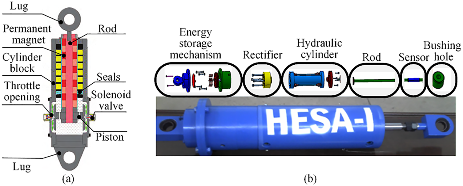
Figure 14: (a) Structure principle of electromagnetic compound energy regenerative suspension mechanism; (b) Hydraulic regenerative suspension mechanism with HMR
When the speed of the hydraulic motor-driven generator is lower than the minimum working speed of the generator, the hydraulic-electric composite energy regenerative suspension system will produce the phenomenon of a “power dead zone”. Zhou et al. [83,84] increased the speed of the hydraulic motor by reducing the displacement of the hydraulic motor, and adjusted the minimum working speed of the generator to avoid the phenomenon of a “power dead zone”, to improve the reliability of the hydraulic-electric composite energy regenerative suspension system. However, the recovery of vibration energy inevitably leads to the degradation of the dynamic performance of the hydraulic-electric composite energy regenerative suspension. Galluzzi et al. [85] added a rectification to the hydroelectric energy regenerative suspension. The rectification could transfer mechanical power between the linear and rotary domains. In addition, rectification could introduce the potential benefits of reduced wear in the rotating parts and increased volumetric efficiency of the pump. Miragli et al. [86] discussed the main relations ruling the dynamics of a regenerative suspension. They presented a method to build the RV by properly select off-the shelf components, in order to comply with dimensional, performance and safety requirement. The compact design of the RSA, with a mass of only 5.8 kg, allows its installation into the suspension of a B-class SUV.
To improve the ride comfort of the vehicle and realize the decoupling of various motion modes of the vehicle, the conflict between the dynamic reduction performance and energy recovery of the energy regenerative suspension system is avoided. Wang et al. developed a hydraulic-electric composite energy regenerative suspension system by designing a linear motor in parallel with a hydraulic system, as shown in Fig. 15. According to the working range of the motor and the characteristics of the hydraulic system, they divided the working modes of the energy regenerative suspension system: comfort mode, safety mode, and energy regenerative mode to coordinate the contradiction between damping output and energy harvesting. Hydraulic-electric composite energy regenerative suspension system allows for near-asymmetric rebound/compression damping forces through specific piping connections [87–90]. Zhang et al. [91–93] designed and studied the double-pipe hydraulic-electric composite energy regenerative suspension, as shown in Fig. 16. During the upward and downward movement of the piston, the flow direction of the hydraulic oil and the rotation direction of the motor is not changed, and the unidirectional rotation of the generator is realized to ensure the energy collection capacity. In addition, a check valve is set in the pipeline to achieve a large controllable range of the damping force to ensure the smoothness of the vehicle. Qin [94] proposed a new hydraulic-electric composite energy regenerative suspension system with reliable load-bearing performance and adjustable damping characteristics. It combines the characteristics of the interconnected suspension cross-connection to significantly improve the road adaptability, body stability, and energy regenerative efficiency of the vehicle.
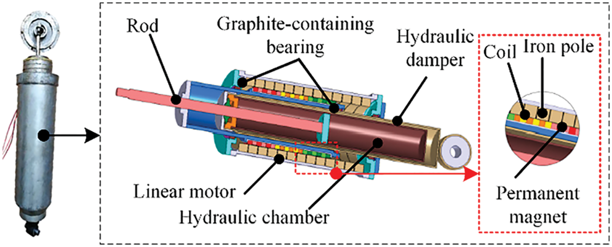
Figure 15: Schematic of new HEMA
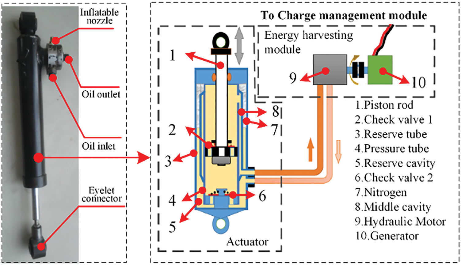
Figure 16: (a) Actuator prototype of the pumping regenerative suspension mechanism; (b) Twin-tube pumping regenerative suspension mechanism
According to the characteristics of the hydraulic-electric composite energy regenerative suspension structure itself, researchers from various countries have carried out simulation and experimental verification on the comfort performance, safety performance, and energy-saving performance, as shown in Table 3. Under certain conditions, the maximum output force of the hydraulic-electric composite energy regenerative suspension is higher than that of the linear motor type and the rotary motor type, but it has the characteristics of easy leakage, low power density, and complex structure, which lead to its use restricted.

This chapter mainly summarizes the structure of the electromagnetic energy regenerative suspension, as shown in Table 4. More efficient and energy regenerative structural solutions are the basis of electromagnetic energy regenerative suspension research, while a more practical optimization design is an effective way to improve the reliability performance of electromagnetic energy regenerative suspension. The research of both provides a strong basis for improving the performance of electromagnetic energy regenerative suspension, which is the key issue of electromagnetic energy regenerative suspension research and development.

3 Optimal Design Method for Electromagnetic Energy Regenerative Suspensions
In the field of electromagnetic energy regenerative suspension research [95], multi-objective optimization [96,97] can simultaneously consider the damping performance and energy regenerative efficiency of the system to accomplish a balance between the objectives. Multidisciplinary optimization is a further development of multi-objective optimization, which considers the reliability of the structure, noise, and other factors caused by parameter uncertainty while focusing on performance [98]. Given the characteristics of multi-disciplinary coupling and uncertainty of the electromagnetic energy regenerative suspension system, as shown in Fig. 17, its design difficulty is increased [99]. At present, under the premise of clarifying the working principle in the electromagnetic energy regenerative suspension systems, researchers from various countries have established hybrid models including mechanical field, magnetic field, temperature field, fluid field, etc. To ensure the accuracy of the model analysis, the researchers adopted the reliability analysis methods to reduce the influence of uncertain factors, and finally combined the optimization algorithms to improve the optimization design efficiency of the electromagnetic energy regenerative suspension.
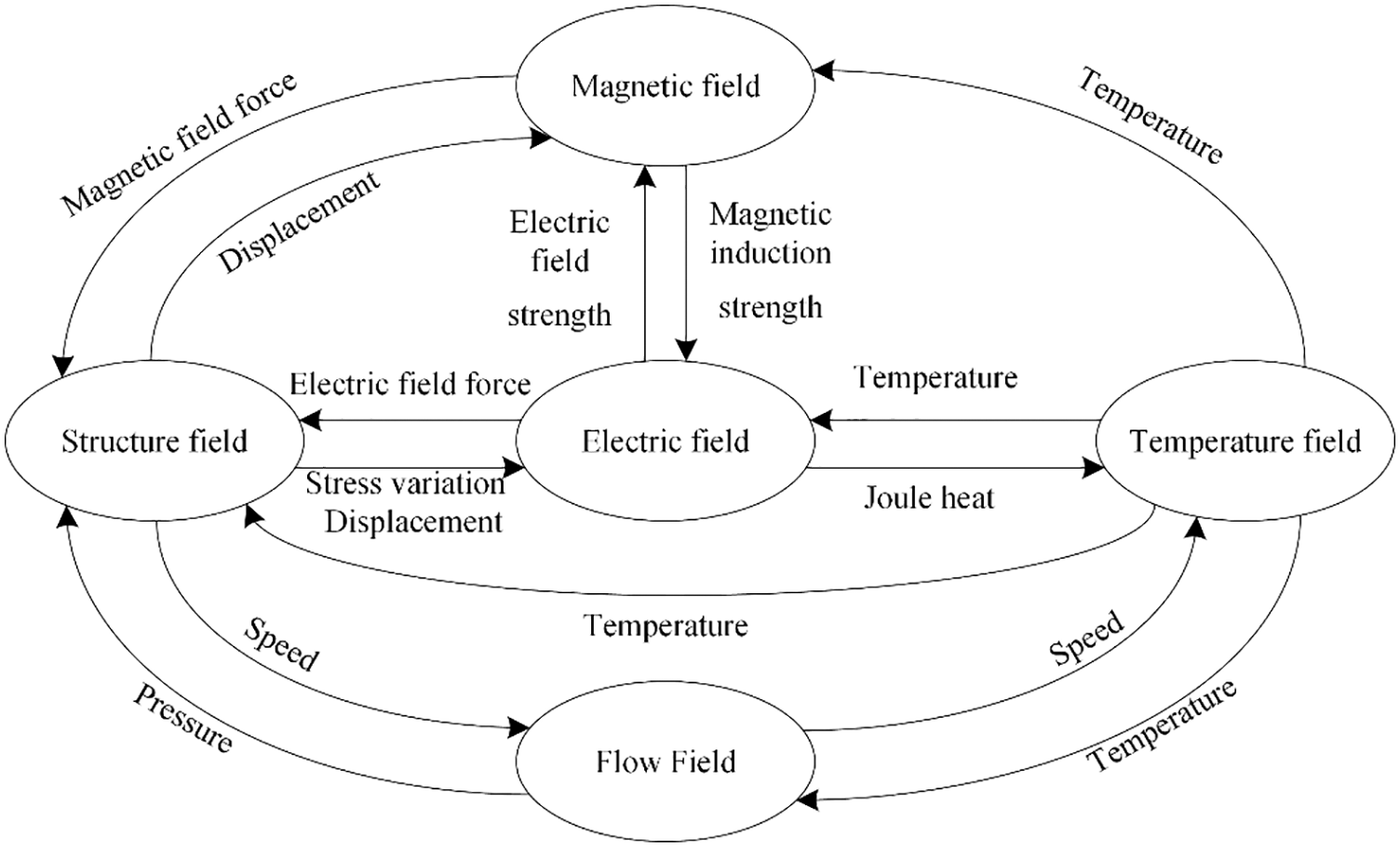
Figure 17: Multi-field coupling relation diagram of fundamental field
3.1 Research of Optimization Models
The disciplines are coupled with each other in the design process of electromagnetic energy regenerative suspension optimization [100]. Establish a multidisciplinary nonlinear coupled model with the support of single discipline theory, and determine the design parameters according to each model output variable. Through the coupling analysis of parameters, the optimization variables of the system are determined, to improve the credibility of the performance analysis results of the electromagnetics, dynamics, and fluid dynamics of the system.
The dynamic analysis of the suspension mainly studies the transmission characteristics of the suspension elastic elements and damping elements to the body of the road vibration excitation [101]. Therefore, most of the current research on dynamic analysis of suspension systems focuses on K&C performance. Zhang [102] proposed a general process for computational suspension system multi-body dynamics modeling and solution. As shown in Fig. 18, it provides a theoretical basis for the multidisciplinary design of electromagnetic energy regenerative suspension. The K&C performance directly affects the damping performance of the electromagnetic energy regenerative suspension system. Wang et al. [103] analyzed the damping performance of the electromagnetic energy regenerative suspension under different road classes based on a hybrid suspension dynamics model, and the body acceleration increased by 2.73%, and the dynamic tire load amplitude decreased by 38.1%. Considering the contradictory relationship between damping performance and energy regenerative performance of the electromagnetic energy regenerative suspension. Kou et al. [104] established a nonlinear model of the energy regenerative suspension and used the least-squares recursive algorithm to identify the parameters of the system model. Coordinate the relationship between dynamic performance and energy regenerative performance. Wang et al. [105,106] added an equivalent circuit model to the electromagnetic suspension model. The relationship between the energy regenerative characteristics and its dynamic performance is clarified, which is only related to tire stiffness, suspension controllable damping, vehicle speed, and road surface.

Figure 18: Multi-body dynamics calculation process
The coupling relationship between the electric and magnetic fields of the electromagnetic energy regenerative suspension is prone to its electromagnetic force fluctuations, and the effective output of electromagnetic damping directly affects the dynamic performance of the system. Yang et al. [107] established an actuator output model with electromagnetic force fluctuations and a quarter vehicle dynamics model, and carried out the dynamic analysis and induced electromotive force harmonic analysis. Peng et al. [108] established a theoretical and simulation analysis model of electromagnetic suspension actuator based on the electromagnetic theory of permanent magnet linear motor, to meet the demand of full linear control four-wheel independent drive electromagnetic active suspension. According to the radial air gap magnetic field distribution, induced electromotive force and other parameters Validate the analytical model. Ataei et al. [109] analyzed the geometry of the electromagnetic suspension actuator using the magnetic circuit method, determined the relationship between design parameters and damping characteristics, and optimized the non-dimensional geometric parameters of the tubular slotless permanent magnet motor, which can obtain a high electromagnetic damping coefficient. Friedrich et al. [110] proposed a semi-analytic model based on the harmonic Fourier model to calculate the magnetic field generated by permanent magnets. The electrical and thermal iterative models are coupled with the magnetic field model into a fast and accurate multidisciplinary design tool, as shown in Fig. 19. The bond graph language can be well adapted to the energy conversion of multi-physics, and it is helpful to analyze the energy flow of the system, so as to clarify the energy harvesting efficiency of the system [111–114]. Lafarge et al. [115] proposed a bond graph model for predicting piezoelectric cantilever beam energy harvesting in automotive suspensions to derive power exchanges between subsystems.

Figure 19: Modeling and analysis process
CFD and finite element methods developed in recent years occupy an important position in multi-body dynamics, electromagnetism, and fluid dynamics. They integrate multidisciplinary theories and high-precision algorithms to accurately calculate and analyze system performance and improve the efficiency of optimal design. CFD and finite element methods are based on geometric models, which need to be parameterized. During the optimization process, the geometric model can be automatically updated according to the optimization variables, thus finding the optimal design solution among the executable design solutions. Zhou et al. [116] built a 1/4 vehicle dynamics model on the AMEsim simulation platform for the new hydraulic-electric energy regenerative suspension system and optimized the hydraulic-electric energy regenerative suspension system with ride comfort as a constraint. Average power increased by 12.7%. Wang et al. [117] used the finite element analysis software Ansoft to determine the magnetization method of the permanent magnets inside the motor of the hydraulic-electric energy regenerative suspension. Zhang et al. [118] used the electromagnetic field simulation software JMAG to build a finite element model of a permanent magnet synchronous motor, combined with Simulink to build a JMAG-RT model, and combined with a DSP controller to build a hardware-in-the-loop system of a permanent magnet synchronous motor.
At present, researchers have carried out a variety of modeling methods to further deepen the dynamic, electromagnetic, and fluid mechanics analysis of the electromagnetic energy regenerative suspension system. The multidisciplinary coupled model is established under the support of single discipline theory and combined with finite element analysis software, the analysis efficiency of system performance is improved.
3.2 Uncertainty Analysis Methods
The electromagnetic energy regenerative suspension system is a multi-disciplinary strong coupling nonlinear uncertainty system, and its uncertainty is divided into parameter uncertainty and model structure uncertainty [119]. The operating state of the electromagnetic energy regenerative suspension system varies with the road surface and climate, leading to uncertainties in its estimated parameter characteristics. Uncertainty in the model structure due to different assumptions in the modeling process of electromagnetic energy regenerative suspensions [120]. The uncertainty will directly affect the performance of the electromagnetic energy regenerative suspension system. Therefore, the uncertainty analysis of electromagnetic energy regenerative suspension structures by researchers from various countries mainly focuses on the influence of uncertainty input on the structural response. According to the application in practice, the commonly used uncertainty analysis methods are mainly divided into reliability analysis and robustness analysis, and the comparative analysis is shown in Table 5.

Reliability analysis can obtain the failure probability of the system. In the research of electromagnetic energy regenerative suspension systems, reliability analysis ensures the driving safety of the vehicle; robustness analysis estimates the sensitivity of uncertainties to the system response and achieves controllable product quality characteristics [121]. According to the requirements of the comfort, safety, and energy-harvesting performance of the energy regenerative suspension system [122]. Scholars currently use robustness analysis methods to conduct in-depth research on the suspension system, such as the Taguchi method, Monte Carlo method, etc. To reduce the influence of uncertainty factors on the comprehensive performance of electromagnetic energy regenerative suspension systems.
The Taguchi method was first proposed by Taguchi Genichi, and the basic idea is to determine the output response by adjusting the control factor and considering the effect of uncertainty factors while the input response is constant [123,124]. To reduce the variation of vehicle ride comfort with sprung mass, Mitra et al. [125] used the Taguchi method to analyze the ride performance of vehicle suspension, looking for the relationship between tire pressure, spring stiffness, and damping coefficient to determine the constant target comfort value. Reddy et al. [126] used an optimization method combining the response surface method and the Taguchi method to analyze the suspension system of the vehicle suspension. The response surface method can derive the main factors affecting the suspension performance parameters and the Taguchi method can predict the parameters of the suspension system to verify the accuracy of the response surface method. Liu et al. [127] used the Taguchi method to find the optimal combination of suspension parameters based on the Kriging surrogate model. The method adopted improved the lateral and longitudinal stability of the vehicle by 10.08% and 9.18%. Zhang et al. [128] used the Taguchi method to analyze the energy regenerative efficiency of the energy regenerative suspension system under the grades A, C, and E of IS08606.
The Monte Carlo method can determine the correlation between random variables in the suspension system to ensure high confidence in the system analysis results. Hamid et al. established a dynamic model of the commercial vehicle suspension system and used Monte Carlo analysis to obtain the correlation between the energy regenerative power and driving conditions under different suspension and road conditions [129]. Zhang et al. [130] used the Monte Carlo method to analyze the parameter sensitivity of the indirect-driven and direct-driven energy regenerative suspension systems and compared the performance of the two systems in improving the peak power output and broadening the energy harvesting frequency band. Abdelkareem et al. [131] used the Monte Carlo method for frequency-based parametric sensitivity analysis of vehicle suspension dynamics and energy harvesting potential to reveal the relationship between suspension parameters and energy regenerative, which helps to conceptualize the design of electromagnetic energy regenerative suspension systems to improve their energy regenerative efficiency under different road conditions.
The uncertainty analysis method can further clarify the correlation of the performance parameters of the electromagnetic energy regenerative suspension system, which helps to make trade-offs among the performance parameters and then coordinate the performance requirements of the electromagnetic energy regenerative suspension system to meet the researchers’ requirements on the damping performance, energy regenerative performance and safety performance of the electromagnetic energy regenerative suspension system.
3.3 Research of Optimization Algorithms
In the optimization process, advanced optimization algorithms are the key to improving the efficiency of optimal design and promoting multidisciplinary and multi-objective optimization to practical applications. The objects of multidisciplinary optimization are generally nonlinear systems. Therefore, the optimization algorithms are mainly nonlinear programming methods. The commonly used optimization algorithms are shown in Table 6, which are roughly divided into two categories: classical optimization algorithms and intelligent optimization algorithms. Classical optimization algorithms include the direct search method [132], penalty function method [133], conjugate gradient method [134], and quasi-Newton method [135], whose theories are very mature. The intelligent optimization algorithm has the self-adaptive characteristics of organisms in the face of environmental changes in nature, cooperates, and shares information in the process of finding the optimal solution, which ensures the robustness and stability of the algorithm. Intelligent algorithms include simulated annealing algorithm [136], genetic algorithm [137], ant colony algorithm [138], particle swarm algorithm [139], etc. At present, genetic algorithm and particle swarm optimization algorithm has been well applied in the optimal design of electromagnetic energy regenerative suspension.

In the optimization design process of the electromagnetic energy regenerative suspension, the parameters involved in the genetic algorithm are random. This stochastic search characteristic makes the genetic algorithm has strong robustness in the operation process, and the search mode is not limited to a certain point, expanding the search range and easy to obtain the global optimal solution. Li et al. [140] proposed a multi-objective optimization function based on weight coefficients and applied multiple genetic algorithms with strong search capability and fast convergence to optimize the mechanism size of the motor. Compared with the standard genetic algorithm, the multiple genetic algorithms used can effectively suppress the premature convergence problem of the SGA algorithm. Based on a comprehensive genetic algorithm, Shao et al. designed an adaptive function to optimize the parameters of the electromagnetic energy regenerative suspension and the active controller. The optimized electromagnetic energy regenerative suspension improved the ride comfort of the vehicle [141]. Li et al. [142] evaluated the performance of electromagnetic energy regenerative suspension system based non-dimensional mixed index of safety probability and used a genetic algorithm to optimize the smoothness and maneuvering stability indexes of the system. The optimization alleviated the contradictory problem between the two and ensured the maneuvering stability based on improving the smoothness of the suspension. Kou et al. [143] used a genetic algorithm to coordinate the damping performance and energy regenerative performance of the electromagnetic energy regenerative suspension system, and the optimized spring-loaded mass acceleration was reduced by 22.23% and the energy regenerative power was increased by 40.51%. The regenerative performance of the electromagnetic energy regenerative suspension is improved while ensuring a certain level of vehicle comfort and driving safety.
Compared with the genetic algorithm, the particle swarm algorithm contains fewer parameters, runs faster, and is easy to implement, but like a genetic algorithm, it is easy to fall into local optimum. Yu et al. [144] introduced a multi-objective particle swarm optimization algorithm to obtain the Pareto front in the optimal design of electromagnetic energy regenerative suspension, applied hierarchical analysis to find the optimal design of the Pareto front, and verified the feasibility of multi-objective optimization and multi-objective decision-making methods. Zhou et al. [145] added a learning framework to the optimization process and developed a recent particle swarm global optimization algorithm that combines human knowledge for local optimization. The new algorithm reduces the computational load by reducing the learning space, and the optimized electromagnetic energy regenerative suspension achieves maximum energy efficiency with the best-optimized design parameters. Peng et al. [146] optimized the actuator structure parameters of electromagnetic active suspension based on a multi-objective particle swarm optimization algorithm with adaptive penalty function, and the optimized actuator structure is compact and loss reduction. Based on this, Yang et al. [147] used linearly adjusted inertia weight coefficients combined with a particle swarm optimization algorithm to optimize and improve the system, which eliminated the influence of the electromechanical coupling problem on the dynamic performance of the electromagnetic energy regenerative suspension system. Li et al. [148] used a multi-objective particle swarm optimization algorithm to optimize the road adaptability of the electromagnetic energy regenerative suspension system. The optimized electromagnetic energy regenerative suspension system can realize the comprehensive optimization of the safety, comfort, and energy harvesting of the suspension system under different road grades.
By using the optimization algorithm, the loop nesting problem existing in the system optimization design process is solved, and the sensitivity to uncertain factors and the optimization efficiency is improved. The current optimization algorithm still has the problems of premature convergence and insufficient diversity when solving the multidisciplinary optimization design problem of the electromagnetic energy regenerative suspension system.
At present, researchers at home and abroad have achieved certain results in the optimization design of electromagnetic energy regenerative suspension. The optimization process is shown in Fig. 20, which verifies the feasibility of the multidisciplinary and multi-objective optimization design method applied to the optimization design of electromagnetic energy regenerative suspension. However, due to the imperfection of multidisciplinary and multi-objective optimization design itself, as well as the complexity of the electromagnetic energy regenerative suspension system, the current optimization design method still has many shortcomings, such as large calculation volume and convergence difficulties. Therefore, we need to improve and refine the optimization method itself, and then better integrate the multidisciplinary and multi-objective optimization design method according to the performance characteristics of the electromagnetic regenerative suspension to improve the comprehensive performance of the electromagnetic regenerative suspension system.
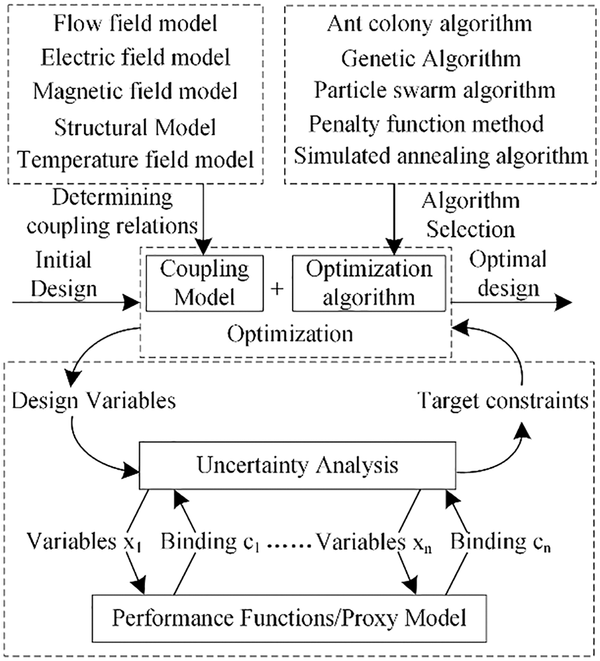
Figure 20: An optimization framework
4 Electromagnetic Energy Regenerative Suspension Control Methods
In the design and research process of the electromagnetic energy regenerative suspension at this stage, the electromagnetic energy regenerative suspension structure and the system controller are the key contents of the research. A good structure can ensure the dynamic performance of the electromagnetic energy regenerative suspension, and the system controller is responsible for calculating the control rate to optimize the vehicle’s motion posture [149,150]. The coordinated control of the dynamic performance and the energy regenerative performance of the electromagnetic energy regenerative suspension is a key problem that needs to be broken through. In past research, researchers have analyzed the feasibility of the electromagnetic energy regenerative suspension system from a single perspective [151]. As the performance requirements of electromagnetic energy regenerative suspensions continue to improve, the control methods of electromagnetic energy regenerative suspensions are constantly being improved, allowing them to change their vibration and energy regenerative characteristics according to specific requirements to improve the overall performance of electromagnetic energy regenerative suspensions. At present, the control methods of electromagnetic energy regenerative suspension are mainly divided into three categories: classical control methods, modern control methods, and intelligent control methods.
Classical control theory is a theory based on the frequency response method and the root trajectory method, using the Laplace transform as a mathematical tool, and has significant results for linear time-invariant systems with a single input and a single output [152,153]. With the application of the state space method and the development of the control theory, the current control method can solve the multi-dimensional space system with multiple inputs and multiple outputs. At present, the classical control theories applied to the energy regenerative suspension include skyhook control, groundhook control, LQG control, etc.
4.1.1 Skyhook Control & Groundhook Control
The skyhook control algorithm was first proposed by Karnopp in the United States and was originally used for the control of semi-active suspension [154]. With the development of the suspension system and the deepening of control research, it has been developed into ideal skyhook control [155], skyhook active control [156], and skyhook on-off control [157].
To improve the practicality and effectiveness of semi-active control of energy regenerative suspensions, Chen et al. [158] proposed the skyhook on-off control algorithm. Compared with the skyhook active control, the skyhook on-off control can well suppress the vertical body vibration acceleration in the low-frequency resonance region, mid-frequency region, and high-frequency region, and improve the smoothness of vehicle driving. Moallem et al. [159] used a regenerative skyhook control strategy, which can achieve continuous variable damping force output of the electromagnetic suspension, significantly improve the damping performance of the suspension and enhance the energy harvesting efficiency of the system. To coordinate the relationship between the dynamic performance and energy consumption of the hybrid electromagnetic suspension, Wang et al. [160–162] determined the conditions for multi-mode switching of the system. They adopted a mode switching control method based on skyhook control to realize the fast and slow switching control of the electromagnetic suspension system in all road conditions, ensuring the stability of mode switching.
The control principle of groundhook control is the same as that of skyhook control [163]. Kopylov et al. [164] proposed an acceleration-based groundhook control method for electromagnetic energy regenerative suspensions to improve the energy regenerative capability under random road surfaces. Kou et al. [165] divided the suspension movement into four modes: economy, safety, comfort, and comprehensive according to the driving conditions of the vehicles, and adopts endocrine composite skyhook-groundhook control, as shown in Fig. 21. Compared with the skyhook-groundhook control, the endocrine composite skyhook-groundhook shed control has a better damping effect and better adaptability to the simulation of changing parameters.
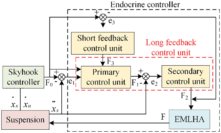
Figure 21: Block diagram of the control structure of the endocrine compound world shed
LQG (Linear Quadratic Guass) optimal control is a classic optimal control algorithm [166,167], and its working principle is shown in Fig. 22. Compared with skyhook control and groundhook control, LQG control has great advantages in the robustness of the control system. The design of the weighting matrices Q and G is the core of the LQG active control algorithm. The traditional method to determine the values of the weighting matrices is less efficient and difficult to obtain the optimal solution. The global search ability of intelligent algorithms such as genetic algorithms and fruit fly algorithms can improve the optimization efficiency of LQG.
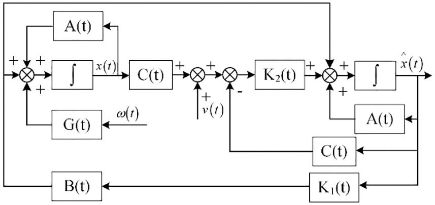
Figure 22: LQG control system block diagram
There are three main performance evaluation indexes for energy regenerative suspensions, which are body acceleration representing ride comfort, suspension dynamic deflection representing safety, and average energy regenerative efficiency representing energy regenerative characteristics [168]. Hansen uses the LQG optimal control method to coordinate the relationship between the performance indicators of the electromagnetic energy regenerative suspension and the output force [169]. Wang et al. [170,171] used the LQG control method to determine the damping value in different working modes and achieved the mode switching control of the electromagnetic energy regenerative suspension. Dai et al. [172] used optimal control theory to design the active suspension LQG controller, and used hierarchical analysis (AHP) and particle swarm optimization (PSO) methods to optimize the controller design parameters. An optimized controller improves vehicle dynamics and energy regenerative efficiency. Kou et al. [173,174] used an improved fruit fly algorithm to optimize the weighting coefficients of LQG under different fitness functions, which improved the adaptive performance of the control system under mixed grade pavement.
Traditional control methods are simple, reliable, and easy to implement. However, traditional control methods require high precision system models. They are difficult to meet the high-performance requirements of the electromagnetic energy regenerative suspension system, when solving the performance coordination problem of the electromagnetic energy regenerative suspension system. With the continuous development of theories in various disciplines, the combination of advanced algorithms can improve the adaptability of traditional control methods to complex coupled systems.
Modern control methods do not require parameter identification, but need to define the variation law of adaptive parameters to reduce system errors and ensure system stability. They are suitable for complex systems such as multi-input multi-output systems and nonlinear systems. They are the characteristics of clear theory and convenient operation. Modern control methods mainly include: adaptive control, sliding mode control, robust control, etc.
In the 1960s, the concept of adaptive control was proposed by Aseltine, and it was first used for control problems in the aerospace field [175]. Adaptive control has fast adaptability to the system with parameter changes and model uncertainty. As shown in Fig. 23, it can automatically adjust the system according to the output state of the controlled object, so that the system is always in the best condition [176,177]. In the control process of the electromagnetic energy regenerative suspension system, there are a large number of nonlinear uncertain factors that interfere with the control performance of the system [178,179], so as to affect the dynamic performance of the electromagnetic energy regenerative suspension system. Therefore, adaptive control is suitable for electromagnetic energy regenerative suspension systems.
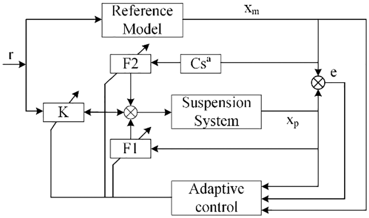
Figure 23: The structure block diagram of adaptive control
In recent years, researchers have adopted adaptive control for the electromagnetic energy regenerative suspension system, which improves the dynamic performance and energy regenerative performance of the electromagnetic energy regenerative suspension system and ensures its safety performance. Li et al. [180] adopted the adaptive filter compensation method to reduce the influence of nonlinear factors on the electromagnetic energy regenerative suspension system. By controlling the first-order resonance of the suspension system, the effective output force of the electromagnetic suspension is amplified, which ensures the dynamic performance of the electromagnetic energy regenerative suspension system. Min et al. [181] used an adaptive fuzzy output feedback inverse optimization strategy to achieve the inverse optimization related to the energy consumption function, which ensured the stability of the vehicle attitude. Sun et al. [182] adopted the fuzzy adaptive backstepping control method to precisely and precisely control the active suspension system, which not only improved the comfort but also ensured safety. For uncertain nonlinear systems with dead-zone actuators and random failures, Hua et al. [183] used an adaptive control strategy to compensate for the unknown dead-zone input nonlinearity of the automotive suspension system and improve the dynamic response performance of the system. Liu et al. [184] used the adaptive back-thrusting method to ensure the boundedness of the failure probability of the electromagnetic suspension system. Pan et al. [185] proposed an adaptive fault-tolerant method to comprehensively compensate for the controller performance. The proposed control method can achieve arbitrarily small tracking errors in the presence of random failures in nonlinear systems.
Sliding mode control, also known as variable structure control, is essentially discontinuous nonlinear control and was first proposed by Utkin [186]. Sliding mode control is characterized by high control accuracy, fast convergence, robustness, and easy implementation of controller design. Sliding mode control can quickly switch the control state of the system on the pre-designed sliding mode surface with high frequency switching characteristics, which is suitable for mode switching control of electromagnetic energy regenerative suspension systems.
Due to the different working characteristics of the electromagnetic energy regenerative suspension modes, the mode switching is prone to generate thrust fluctuations, and it is difficult to achieve smooth dynamic control of the switching process. Shi et al. [187] combined fuzzy control based on sliding mode control, which eliminated the discontinuous chattering of sliding mode control, maintained the stability of the system, improved the control effect of the suspension system, and improved the performance and energy recovery utilization of electromagnetic energy regenerative suspension system. However, the adaptive performance of the electromagnetic energy regenerative suspension under different road grades needs to be improved. Li et al. [148] designed an adaptive sliding mode controller. They comprehensively considered issues such as the uncertainty of sprung mass caused by fuel consumption, the number of passengers, and cargo load during vehicle driving, and realized the comprehensive optimization of the safety, comfort, and energy efficiency of the suspension system under different road classes. The phenomenon of system instability exists when the electromagnetic energy regenerative suspension fails. Xu et al. [188,189] established a dual sliding mode switching control system for its active mode and failure mode, as shown in Fig. 24. They use the Kalman filter estimation algorithm to continuously detect the dynamic characteristics of the vehicle suspension system. When the electromagnetic energy regenerative suspension system fails, the dual sliding mode switching control strategy controls it to switch to the failure mode to ensure the driving safety of the vehicle.
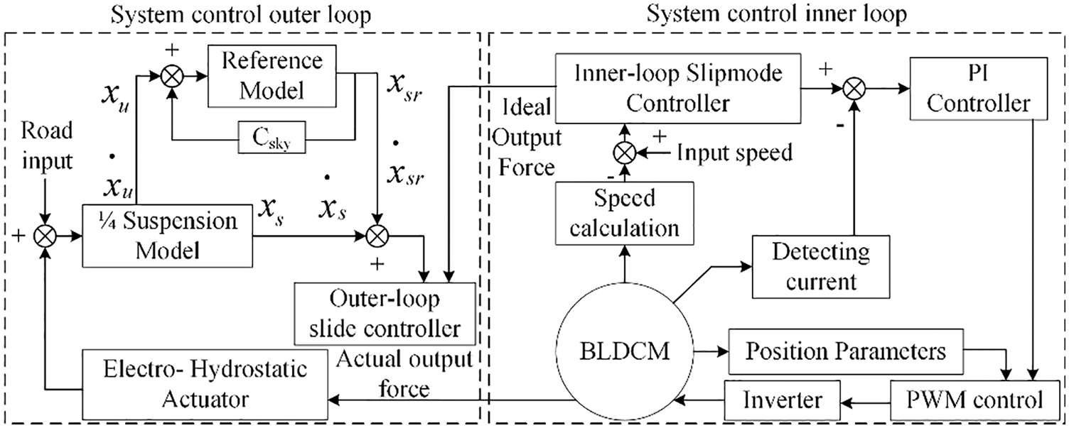
Figure 24: A double sliding mode control strategy of the active suspension mechanism
In 1978, Davison of the University of Toronto first proposed robust control [190], and subsequently developed various control methods such as H∞ robust control [191] and structural singular value theory [192]. Among them, the application of H∞ control in the energy regenerative suspension system is relatively mature. The basic idea is to use the H∞ parametric optimal regulation of the controlled system to ensure the robustness of the system. Effectively solve the influence of disturbance information such as noise and uncertainty on system stability. At present, it has applications in many fields such as electromagnetic energy regenerative suspension systems.
Electromagnetic energy regenerative suspension systems are nonlinear systems with bounded uncertain parameters, which can be transformed into robust problems with linear intervals. Thereby, the control performance of the electromagnetic energy regenerative suspension system is improved. Joo et al. [193] verified that the nonlinear feedback controller of the electromagnetic suspension system is robust to mass parameter perturbation and force perturbation. According to the working area of the actuator in the electromagnetic energy regenerative suspension, Zhang et al. [194] used robust control to design the controller of the vehicle suspension, and realized that the constraining strategy of the controller and the motor working area was consistent. Gysen et al. [195] considered the control of a novel high bandwidth electromagnetic active suspension system for a quarter car model in both simulations and experiments. They took white noise as the random road signal input to the system, and adopted an improved robust controller. The control principle was shown in Fig. 25. The improved robust controller achieved a comprehensive improvement in comfort performance and handling stability performance of the electromagnetic energy regenerative suspension system, with a 41.2% improvement in comfort and a 31.4% improvement in handling performance. Jibril et al. [196] combined H∞ and μ-synthesis to improve the acceleration and motion travel of the suspension and improve the road holding of the vehicle. Roinila et al. [197] designed and tested H∞(H) control structures suitable for cascade and direct control methods. On the premise of ensuring low energy consumption of the suspension system, the method broadens the control bandwidth of the system and improves the low-frequency performance of the suspension system. According to the performance requirements of the suspension system under fault conditions, Jeyasenthil et al. [198] had designed the robust controller on quantitative feedback theory. This controller had achieved similar performance to passive fault-tolerant control. The problem of dynamic performance in the state of electromagnetic energy regenerative suspension failure was solved, and the driving safety of the vehicle was ensured.
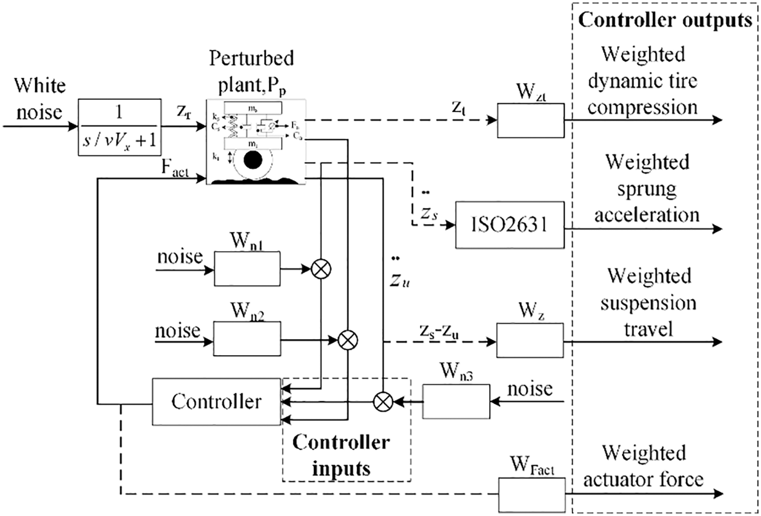
Figure 25: Schematics used for the design of robust control
Modern control methods have better suppression of nonlinear effects, uncertainty factors and environmental disturbances in electromagnetic energy regenerative suspension systems. They can realize the closed-loop stable control of the system, which makes up for the shortcomings of traditional control. And they have obvious advantages in improving the dynamic performance, energy regenerative performance and safety performance of the electromagnetic energy regenerative suspension system.
4.3 Intelligent Control Methods
The intelligent control method is a control method spanning multiple disciplines that have been continuously developed based on “classical control” and “modern control”, combined with advanced technologies in different fields [199]. The multidisciplinary coupling of the electromagnetic energy regenerative suspension system leads to the complexity of the modeling process, the increase of nonlinearity and uncertainty factors of the model, and the inability to obtain an accurate mathematical model. This makes it difficult to achieve optimal control of the electromagnetic energy regenerative suspension using previous control methods. Therefore, intelligent control methods such as fuzzy logic control, neural network control and model-free control have become the research hotspots in the field of electromagnetic energy regenerative suspension control. The use of intelligent control to handle the unknown dynamics of the electromagnetic energy regenerative suspension system is estimated to ensure the stability of the control system and to help improve the overall performance of the electromagnetic energy regenerative suspension system.
Neural network control has strong nonlinear approximation capability, self-learning capability, and the ability to obtain the corresponding neural network model according to the input and output characteristics of the controlled system. In the process of engineering application, there are uncertain factors in the complex model of the electromagnetic energy regenerative suspension system. Neural network control has strong fitting ability to uncertainty functions, especially for uncertain nonlinear systems, which ensures that the system has strong adaptability.
Liu et al. [200] used a convolutional neural network to identify the road type, which can adjust the controller parameters according to the output response of the suspension system under different road excitation, thus ensuring that the suspension maintains optimal performance under different road surfaces. Chen et al. [201] introduced a Boost/Buck type DC-DC converter in the circuit of the energy regenerative suspension system and designed an adaptive offline neural network inverse controller. The adaptive offline neural network inverse controller enables the electromagnetic damping force to better track the ideal force and improves the comfort and smoothness of the vehicle, but the regenerative efficiency is not significant. Liu et al. [202] designed a PID controller based on the BP neural network algorithm, as shown in Fig. 26, to perform PI control on the energy regenerative circuit. The energy regenerative suspension can effectively improve the vehicle performance under different input conditions; and the system can recover part of the suspension vibration energy, in which the energy regenerative efficiency is stable at about 55% and the energy regenerative efficiency is stable at about 16%.
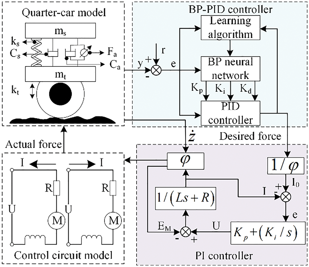
Figure 26: Energy regenerative active suspension based on BP neural network PID control
Fuzzy control is an intelligent control algorithm developed based on Zade’s fuzzy set theory [203], which does not require a precise mathematical model and achieves good control effects by establishing expert experience in formulating fuzzy control rules.
Su et al. [204] applied the T-S fuzzy model to a nonlinear electromagnetic suspension system for the first time, and used a fuzzy state feedback controller to ensure that the required hybrid e2-e∞ performance of the electromagnetic suspension system was achieved. Choi et al. [205] used a T-S fuzzy control system to describe an extended system containing electromagnetic energy regenerative suspension and road disturbance information, and the resulting closed-loop electromagnetic energy regenerative suspension control system is asymptotically stable and has good robustness. Sivakumar et al. [206]. used a fuzzy controller to control the seven-degree-of-freedom suspension system, which reduced the body displacement and acceleration magnitude, eliminated the body-induced resonance peaks, and ensured the smoothness of the body. To make the vehicle achieve more stringent comfort, Mahmoodabadi et al. [207,208] proposed an optimal adaptive fuzzy controller based on a gravity search algorithm. The gravitational search algorithm optimizes the control parameters to reduce the acceleration of the body, the relative displacement between the tires and the sprung mass. To improve the control effect of the electromagnetic energy regenerative suspension based on the fuzzy control strategy, Kou et al. [209] designed a novel endocrine compound fuzzy control strategy, as shown in Fig. 27. The control effect of endocrine compound fuzzy control is better than fuzzy control, which improves the dynamic performance of the system and achieves vibration energy regeneration.
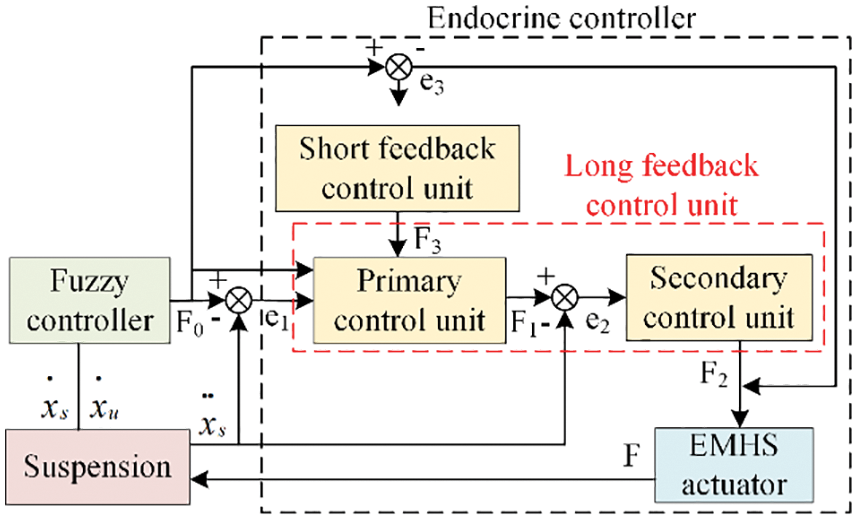
Figure 27: Control structure block diagram of endocrine composite fuzzy
Model-free control is not limited by the specific mathematical model of the system, and only uses the input and output data of the nonlinear system to be controlled to complete the real-time control of the system, improving the robustness of the controller in the energy regenerative suspension system [210].
Yonezawa et al. [211–213] can achieve a model-free design that does not require an actual object model by designing a controller for a 2-DOF system consisting of actuators and virtual objects. The hybrid Eta(2)/Eta(∞) control theory is used to achieve high vibration control performance and robust stability against actuator uncertainty. Combined with sliding mode control theory, a controller that compensates for the uncertainty of actuator parameters is designed to improve the robustness of the system to the parameters of the actuator, thereby ensuring the vibration suppression performance of the system. Wang et al. [214] proposed a novel scheme of model-free finite-time tracking control methods to achieve the motion control of the active suspension system. They estimated the vertical dynamics of the suspension including external disturbances through the time-lapse estimation method. The error generated in the estimation process was compensated by the integral sliding mode control. In the process of model running, the combination of delay estimation method and integral sliding mode control method can effectively prevent the occurrence of jitter. x. Based on the contradictory relationship between the three performance indicators of the suspension (ride smoothness, suspension dynamic deflection and road holding), Ghazally Ibrahim Yousif Mustsfa used a model-free fractional order sliding mode control method, as shown in Fig. 28. This approach resolves the conflict between ride comfort and driving safety [215].
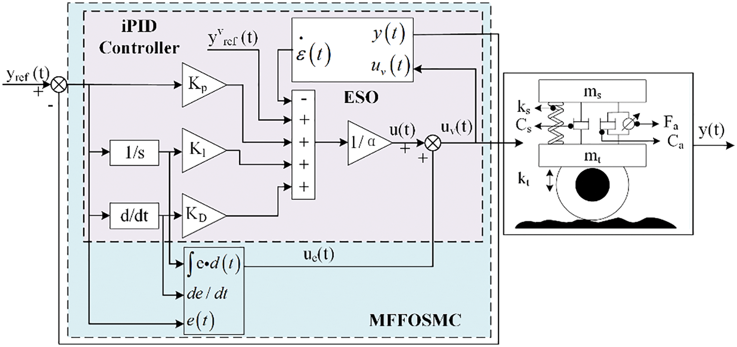
Figure 28: MFFOSMC control structure
Researchers using intelligent control technology can abstract the control problem of the electromagnetic energy regenerative suspension system, combined with artificial intelligence technology, coordinate the relationship between its system performance, and improve the comprehensive performance of the electromagnetic energy regenerative suspension system.
This chapter summarizes the research status at home and abroad related to the electromagnetic energy regenerative suspension control system, and classifies the control methods. As shown in Table 7, the concepts of different control methods and their manifestations in the electromagnetic energy regenerative suspension control system are analyzed. Obviously, it is difficult to meet high-performance requirements for electromagnetic energy regenerative suspensions only by using traditional control methods. With the continuous development of control theory, the application of modern control technology and intelligent control technology in the electromagnetic energy regenerative suspension system tends to mature, but it still has its limitations. For example, the rules of fuzzy control are difficult to obtain accurately, and the training period of neural network control is long. Finding more effective control methods is the key to current research in electromagnetic regenerative suspension control technology.

This paper provides a comprehensive review of the structure, optimization methods, and control strategies of electromagnetic energy regenerative suspensions, according to the research status of the electromagnetic energy regenerative suspension by researchers from various countries. Driven by low carbonization, intelligence and informatization, the researchers gradually realize the transition from passive energy consumption to energy harvesting in the suspension system of the vehicle. However, there are still many key technical problems in the development process of the energy regenerative technology of electromagnetic suspensions, such as the contradiction between energy regeneration and dynamic performance, lightweight problem, motor dead zone and so on. These will play a key role in promoting the development of electromagnetic energy regenerative suspensions in the future. In the author’s view, a more reliable and energy-efficient structural solution is the basis for the research of electromagnetic energy regenerative suspension. A more realistic and optimized design method is an effective way to improve the reliability of electromagnetic energy regenerative suspension. And a more effective control method is the key to improving the comprehensive performance of electromagnetic energy regenerative suspension. Therefore, by reviewing the structural form, optimization method, and control strategy of the electromagnetic energy regenerative suspension, it is found that the electromagnetic energy regenerative suspension system has the following development laws:
• The damping performance and energy regeneration of the rotary motor regenerative suspensions are remarkable, but the wear problem of its own mechanical structure cannot be ignored. The maximum output force of the hydraulic-electric electromagnetic energy regenerative suspensions is higher than that of the rotary and linear structures, but the hydraulic systems have problems such as easy leakage and low power density. The linear motor regenerative suspensions have high-performance requirements such as compact structure, high-frequency response, high accuracy, and high power-to-weight ratio compared with the rotary motor type and hydraulic-electric regenerative suspension. Therefore, the linear motor regenerative suspensions meet the development requirements of the electromagnetic energy regenerative suspension system in the future.
• The electromagnetic energy regenerative suspension is a multi-disciplinary strong coupling complex system, which has the characteristics of multi-function and parameter uncertainty. It increases the design difficulty. In the optimization design process of electromagnetic energy regenerative suspension, the establishment of a multidisciplinary coupling model is the basis of system performance analysis. The correlation of performance parameters can be further clarified through uncertainty analysis, and the optimization design efficiency can be improved by combining optimization algorithms. In future research, it is necessary to establish a more accurate system dynamic model, and improve the stability of the algorithm operation and overcome the problems of local convergence and optimization distortion.
• For the research of the control methods of the electromagnetic energy regenerative suspension systems, researchers have established a certain research foundation about the traditional control methods and the modern control methods. On the basis of this research, intelligent control methods are gradually applied to the electromagnetic energy regenerative suspension systems, and the system control performance is significantly improved, but there are still some limitations. Therefore, future related research should utilize the advantages of traditional control methods and modern control methods, and combine the adaptability of intelligent control methods in complex models. We also need to combine research with practical applications, take more consideration of the actual working conditions of the electromagnetic energy regenerative suspension systems, and gradually realize the improvement in the performance of the electromagnetic energy regenerative suspension system in the actual operating environment.
Funding Statement: This work was supported by the National Natural Science Foundation of China (51975341, 51875326, and 51905319); Shandong Provincial Natural Science Foundation, China (ZR2021QE180); the Young Technology Talent Supporting Project of Shandong Province (2021KJ083); and SDUT & Zhangdian District Integration Development Project (2021JSCG0015).
Conflicts of Interest: The authors declare that they have no conflicts of interest to report regarding the present study.
References
1. Armendariz-Lopez, J. F., Arena-Granados, A. P., Gonzalez-Trevizo, M. E., Luna-Leon, A., Bojorquez-Morales, G. (2018). Energy payback time and greenhouse gas emissions: Studying the international energy agency guidelines architecture. Journal of Cleaner Production, 196, 1566–1575. DOI 10.1016/j.jclepro.2018.06.134. [Google Scholar] [CrossRef]
2. Chang, W., Liu, B., Zhu, Y. Y. (2021). The development trend of the auto industry under the dual-carbon goal. Auto Review, 8, 31–35. [Google Scholar]
3. Chinese Society of Automotive Engineering (2020). The technology roadmap for energy saving and new energy vehicles 2.0. China Machine Press, China. [Google Scholar]
4. Shchurov, N. I., Bakholdin, P. A. (2018). The active electromagnetic suspension of vehicle. 2018 XIV International Scientific-Technical Conference on Actual Problems of Electronics Instrument Engineering, pp. 399–401. Novosibirsk, Russian Federation. [Google Scholar]
5. Chu, S., Majumdar, A. (2012). Opportunities and challenges for a sustainable energy future. Nature, 488(7411), 294–303. DOI 10.1038/nature11475. [Google Scholar] [CrossRef]
6. Abdelkareem, M., Lin, X., Ahmed, A., Ahmed, E., Jia, M. et al. (2018). Vibration energy harvesting in automotive suspension system: A detailed review. Applied Energy, 229, 672–699. DOI 10.1016/j.apenergy.2018.08.030. [Google Scholar] [CrossRef]
7. He, X. Y., Xiao, G. X., Hu, B. L., Tan, L. S., Tang, H. B. et al. (2020). The applications of energy regeneration and conversion technologies based on hydraulic transmission systems: A review. Energy Conversion Management, 205, 112413. DOI 10.1016/j.enconman.2019.112413. [Google Scholar] [CrossRef]
8. Genovese, A., Strano, S., Terzo, M. (2018). Model-based study of a resonant system in a railway air spring secondary suspension for energy harvesting applications. Proceedings of the 2018 2nd International Conference on Mechatronics Systems and Control Engineering, pp. 45–51. Amsterdam, Netherlands. [Google Scholar]
9. Zhang, R., Wang, X., John, S. (2018). A comprehensive review of the techniques on regenerative shock absorber systems. Energies, 11(5), 1167. DOI 10.3390/en11051167. [Google Scholar] [CrossRef]
10. Diez-Jimenez, E., Rizzo, R., Gómez-García, M. J., Corral-Abad, E. (2019). Review of passive electromagnetic devices for vibration damping and isolation. Shock and Vibration, 2019, 1250707. DOI 10.1155/2019/1250707. [Google Scholar] [CrossRef]
11. Karnopp, D. (1989). Permanent magnet linear motors used as variable mechanical dampers for vehicle suspensions. Vehicle System Dynamics, 18, 187–200. DOI 10.1080/00423118908968918. [Google Scholar] [CrossRef]
12. Pan, H. Y., Qi, L. F., Zhang, Z. T., Yan, J. Y. (2021). Kinetic energy harvesting technologies for applications in land transportation: A comprehensive review. Applied Energy, 286, 116518. DOI 10.1016/j.apenergy.2021.116518. [Google Scholar] [CrossRef]
13. Rakshith, M., Kumar, Y., Vikas, S. G. (2014). Bose automotive suspension. International Journal of Recent Technology and Engineering, 3, 13–18. [Google Scholar]
14. Xie, L. H., Li, J. H., Cai, S. Q., Li, X. D. (2017). Electromagnetic energy-harvesting damper with multiple independently controlled transducers: On-demand damping and optimal energy regeneration. IEEE/ASME Transactions on Mechatronics, 22, 2705–2713. DOI 10.1109/TMECH.3516. [Google Scholar] [CrossRef]
15. Münster, M., Mair, U., Gilsdorf, H. J., Thomä, A., Müller, C. et al. (2009). Electromechanical active body control. ATZautotechnology, 9(3), 24–29. DOI 10.1007/BF03247116. [Google Scholar] [CrossRef]
16. Hosenfeldt, I. T., Musayev, I. Y., Schulz, D. I. E. (2013). Schaeffler technologies AG & Co., KG Industriestr. Industriestr. 1--3, 91074 Herzogenaurach, Germany. Advanced Ceramic Coatings and Materials for Extreme Environments III, 34(3), 581. [Google Scholar]
17. Zhao, Z. H., Guan, Y. L., Chen, S. A. (2020). Experimental research on PMSM ball screw actuator and structural design suggestion of featured active suspension. IEEE Access, 8, 66163–66177. DOI 10.1109/Access.6287639. [Google Scholar] [CrossRef]
18. Liu, Y. L., Xu, L., Zuo, L. (2017). Design, modeling, lab, and field tests of a mechanical-motion-rectifier-based energy harvester using a ball-screw mechanism. IEEE/ASME Transactions on Mechatronics, 22(5), 1933–1943. DOI 10.1109/TMECH.2017.2700485. [Google Scholar] [CrossRef]
19. Pan, Y., Lin, T., Qian, F., Liu, C., Yu, J. et al. (2019). Modeling and field-test of a compact electromagnetic energy harvester for railroad transportation. Applied Energy, 247, 309–321. DOI 10.1016/j.apenergy.2019.03.051. [Google Scholar] [CrossRef]
20. Galluzzi, R., Circosta, S., Amati, N., Tonoli, A. (2021). Rotary regenerative shock absorbers for automotive suspensions. Mechatronics, 77, 102580. DOI 10.1016/j.mechatronics.2021.102580. [Google Scholar] [CrossRef]
21. Li, S. Y., Xu, J., Pu, X. H., Tao, T., Gao, H. N. et al. (2019). Energy-harvesting variable/constant damping suspension system with motor based electromagnetic damper. Energy, 189, 116199. DOI 10.1016/j.energy.2019.116199. [Google Scholar] [CrossRef]
22. Li, S. Y., Xu, J., Pu, X. H., Tao, T., Mei, X. S. (2019). A novel design of a damping failure free energy-harvesting shock absorber system. Mechanical Systems and Signal Processing, 132, 640–653. DOI 10.1016/j.ymssp.2019.07.004. [Google Scholar] [CrossRef]
23. Salman, W., Qi, L. F., Zhu, X., Pan, H. Y., Zhang, X. T. et al. (2018). A high-efficiency energy regenerative shock absorber using helical gears for powering low-wattage electrical device of electric vehicles. Energy, 159, 361–372. DOI 10.1016/j.energy.2018.06.152. [Google Scholar] [CrossRef]
24. Wang, Z. W., Zhang, T. M., Zhang, Z. T., Yuan, Y. P., Liu, Y. J. (2020). A high-efficiency regenerative shock absorber considering twin ball screws transmissions for application in range-extended electric vehicles. Energy and Built Environment, 1, 36–49. DOI 10.1016/j.enbenv.2019.09.004. [Google Scholar] [CrossRef]
25. Suda, Y., Shiiba, T. (1996). A new hybrid suspension system with active control and energy regeneration. Vehicle System Dynamics, 25, 641–654. DOI 10.1080/00423119608969226. [Google Scholar] [CrossRef]
26. Beno, J. H., Weeks, D. A., Bresie, D. A., Guenin, A. M., Wisecup, J. et al. (2002). Experimental comparison of losses for conventional passive and energy efficient active suspension systems. SAE Technical Paper, 1, 0282. DOI 10.4271/2002-01-0282. [Google Scholar] [CrossRef]
27. Hayes, R., Beno, J., Weeks, D., Guenin, A., Mock, J. et al. (2005). Design and testing of an active suspension system for a 2–1/2 to military truck. SAE Technical Paper, 1(1715), 2005. DOI 10.4271/2005-01-1715. [Google Scholar] [CrossRef]
28. Papageorgiou, C., Smith, M. C. (2006). Positive real synthesis using matrix inequalities for mechanical networks: Application to vehicle suspension. IEEE Transactions on Control Systems Technology, 14, 423–435. DOI 10.1109/TCST.2005.863663. [Google Scholar] [CrossRef]
29. Li, P., Zuo, L. (2017). Influences of the electromagnetic regenerative dampers on the vehicle suspension performance. Proceedings of the Institution of Mechanical Engineers, Part D: Journal of Automobile Engineering, 231, 383–394. DOI 10.1177/0954407016639503. [Google Scholar] [CrossRef]
30. Guo, S. J., Liu, Y. L., Xu, L., Guo, X. X., Zuo, L. (2016). Performance evaluation and parameter sensitivity of energy-harvesting shock absorbers on different vehicles. Vehicle System Dynamics, 54, 918–942. DOI 10.1080/00423114.2016.1174276. [Google Scholar] [CrossRef]
31. Yu, L. Y., Huo, S. H., Xuan, W. W., Zuo, L. (2015). Assessment of ride comfort and braking performance using energy-harvesting shock absorber. SAE International Journal of Passenger Cars-Mechanical Systems, 8, 482–491. DOI 10.4271/2015-01-0649. [Google Scholar] [CrossRef]
32. Liu, Y. G., Chen, W. W., Zhang, Z. T., Hua, G. (2016). Energy-regenerative shock absorber for transportation vehicles based on dual overrunning clutches: Design, modeling, and simulation. Transportation Research Record, 2551, 126–136. DOI 10.3141/2551-15. [Google Scholar] [CrossRef]
33. Zhang, Z. T., Zhang, X. T., Chen, W. W., Rasim, Y., Salman, W. et al. (2016). A high-efficiency energy regenerative shock absorber using supercapacitors for renewable energy applications in range extended electric vehicle. Applied Energy, 178, 177–188. DOI 10.1016/j.apenergy.2016.06.054. [Google Scholar] [CrossRef]
34. Li, H., Zheng, P., Zhang, T. S., Zou, Y. Q., Pan, Y. J. et al. (2021). A high-efficiency energy regenerative shock absorber for powering auxiliary devices of new energy driverless buses. Applied Energy, 295, 117020. DOI 10.1016/j.apenergy.2021.117020. [Google Scholar] [CrossRef]
35. Guo, S. J. (2018). Influences of the inerter on regenerative suspension dynamics and its damping control (Ph.D. Thesis). Wuhan University of Technology, China. [Google Scholar]
36. Wang, X. Y., Zhang, J. Q., Li, G. Q., Peng, Z. Z. (2019). Influence of inertial mass on rack and pinion actuator′s damping characteristic. Journal of Jilin University, 3, 881–887. [Google Scholar]
37. Chen, X. B., Yin, J., Wang, W., Wu, L. X., Tang, F. (2016). Approaches to diminish large unsprung mass negative effects of wheel side drive electric vehicles. Journal of Advanced Mechanical Design, Systems, and Manufacturing, 10(4), 64. DOI 10.1299/jamdsm.2016jamdsm0064. [Google Scholar] [CrossRef]
38. Yin, J., He, J., Luo, J., Chen, X. B., Wu, L. X. (2019). Research and development of an electromagnetic actuated active suspension. SAE Technical Paper, 1, 0858. DOI 10.4271/2019-01-0858. [Google Scholar] [CrossRef]
39. Jonasson, M., Roos, F. (2018). Design and evaluation of an active electromechanical wheel suspension system. Mechatronics, 18, 218–230. DOI 10.1016/j.mechatronics.2007.11.003. [Google Scholar] [CrossRef]
40. Sllner, T. (2016). The innovative shock absorber system from Audi: New technology saves fuel and enhances comfort. Audi Media Center, 8(10), 16. [Google Scholar]
41. Mohrlock, D., Schindler, A., Beringer, H., Schmitt, J. (2013). Torsion spring system for a wheel suspension of a motor vehicle. US201414768025A. [Google Scholar]
42. Mohrlock, D., Schindler, A., Beringer, H., Schmitt, J. (2015). Torsion bar spring arrangement for a wheel suspension of a motor vehicle. US201414181269A. [Google Scholar]
43. Sun, X. D., Cai, F., Cai, Y. F., Chen, L. (2021). Improved model predictive thrust-force control of linear motors for active suspensions. China Journal of Highway and Transport, 9, 85–100. [Google Scholar]
44. Post, R. F., Ryutov, D. D. (2000). The inductrack: A simpler approach to magnetic levitation. IEEE Transactions on Applied Superconductivity, 10, 901–904. DOI 10.1109/77.828377. [Google Scholar] [CrossRef]
45. Post, R. F. (2003). Inductrack magnet configuration. US 6664880. [Google Scholar]
46. Okada, Y., Harada, H. (1996). Regenerative control of active vibration damper and suspension systems. Proceedings of 35th IEEE Conference on Decision and Control, pp. 4715–4720. Kobe, Japan. [Google Scholar]
47. Wang, J., Wang, W., Tuplin, S., Best, M. (2010). Design and control of a linear electromagnetic actuator for active vehicle suspension. In Advanced Microsystems for Automotive Applications, pp. 311–323. Berlin, Germany. [Google Scholar]
48. Meessen, K. J., Gysen, B. L. J., Paulides, J. J. H., Lomonova, E. A. (2010). 3D field effects in tubular permanent magnet actuators with quasi-halbach magnetization. Digests of the 2010 14th Biennial IEEE Conference on Electromagnetic Field Computation, pp. 1. Chicago Illinois, USA. [Google Scholar]
49. Meessen, K. J., Gysen, B. L. J., Paulides, J. J. H., Lomonova, E. A. (2010). Three-dimensional magnetic field modeling of a cylindrical halbach array. IEEE Transactions on Magnetics, 46, 1733–1736. DOI 10.1109/TMAG.2010.2042038. [Google Scholar] [CrossRef]
50. Gysen, B. L. J., Van Der Sande, T. P. J., Paulides, J. J. H., Lomonova, E. A. (2011). Efficiency of a regenerative direct-drive electromagnetic active suspension. IEEE Transactions on Vehicular Technology, 60(4), 1384–1393. DOI 10.1109/TVT.2011.2131160. [Google Scholar] [CrossRef]
51. Gysen, B. L. J., Paulides, J. J. H., Lomonova, E. A. (2011). Direct-drive electromagnetic active suspension system with integrated eddy current damping for automotive applications. Proceedings of the 8th International Symposium on Linear Drives for Industry Applications, pp. 1. Eindhoven, The Kingdom of the Netherlands. [Google Scholar]
52. Eckert, P. R., Flores Filho, A. F., Perondi, E. A., Dorrell, D. G. (2018). Dual quasi-halbach linear tubular actuator with coreless moving-coil for semiactive and active suspension. IEEE Transactions on Industrial Electronics, 65(12), 9873–9883. DOI 10.1109/TIE.41. [Google Scholar] [CrossRef]
53. Zanatta, A. P., Bandeira Boff, B. H., Eckert, P. R., Ferreira Flores Filho, A., Dorrell, D. G. (2018). Tubular linear permanent magnet synchronous machine applied to semi-active suspension systems. COMPEL-The International Journal for Computation and Mathematics in Electrical and Electronic Engineering, 37(5), 1781–1794. DOI 10.1108/COMPEL-01-2018-0022. [Google Scholar] [CrossRef]
54. Shen, Y. M., Lu, Q. F., Ye, Y. Y. (2016). Double-stator air-core tubular permanent magnet linear motor for vehicle active suspension systems. 2016 IEEE Vehicle Power and Propulsion Conference (VPPC), pp. 1–6. Hangzhou, China. [Google Scholar]
55. Tang, X. D., Lin, T., Zuo, L. (2014). Design and optimization of a tubular linear electromagnetic vibration energy harvester. IEEE/ASME Transactions on Mechatronics, 19(2), 615–622. DOI 10.1109/TMECH.3516. [Google Scholar] [CrossRef]
56. Lei, Z., Scully, B., Shestani, J., Yu, Z. (2010). Design and characterization of an electromagnetic energy harvester for vehicle suspensions. Smart Materials and Structures, 19(4), 5003. [Google Scholar]
57. Lafarge, B., Cagin, S., Curea, O., Perret, A. H. (2016). From functional analysis to energy harvesting system design: Application to car suspension. International Journal on Interactive Design and Manufacturing, 10(1), 37–50. DOI 10.1007/s12008-015-0284-1. [Google Scholar] [CrossRef]
58. Lafarge, B., Grondel, S., Delebarre, C., Curea, O., Richard, C. (2021). Linear electromagnetic energy harvester system embedded on a vehicle suspension: From modeling to performance analysis. Energy, 225, 119991. DOI 10.1016/j.energy.2021.119991. [Google Scholar] [CrossRef]
59. Hyniova, K., Stribrsky, A., Honcu, J., Kruczek, A. (2009). Active suspension system with linear electric motor. WSEAS Transactions on Systems, 8(2), 278–287. [Google Scholar]
60. Hyniova, K., Smitkova-Janku, L., Honcu, J., Stribrsky, A. (2012). On experiments taken by the active shock absorber test stand. Proceedings of the 6th WSEAS International Conference on Computer Engineering and Applications, and Proceedings of the 2012 American Conference on Applied Mathematics, pp. 104–109. Harvard, Cambridge, USA. [Google Scholar]
61. Xiao, X. Y., Wang, Y. Y., He, X., Li, Q. F., Li, H. (2019). Design and simulation analysis of an energy regenerative electromagnetic shock absorber for vehicles. Journal of Applied Science and Engineering, 22(4), 625–636. [Google Scholar]
62. Lai, F. (2015). Experimental circuit design on electromagnetic actuator for vehicle active suspension. Applied Mechanics and Materials, 701, 1201–1204. [Google Scholar]
63. Liu, Y. T. (2021). Multidisciplinary design and analysis of direct-driving electro-hydrostatic actuator (Master’s Thesis). Shandong University of Technology, China. [Google Scholar]
64. Qin, Q. J., Ge, W. Q., Lu, Y. T., Li, B., Tan, C. (2022). Review on key technologies of pump control servo system. Machine Tool & Hydraulics, 50(1), 170–181. [Google Scholar]
65. Jones, R. I. (2002). The more electric aircraft—Assessing the benefits. Proceedings of the Institution of Mechanical Engineers, Part G: Journal of Aerospace Engineering, 216(5), 259–269. DOI 10.1243/095441002321028775. [Google Scholar] [CrossRef]
66. Li, B., Liu, Y. T., Tan, C., Qin, Q. J., Lu, Y. T. (2020). Review on electro-hydrostatic actuator: System configurations, design methods and control technologies. International Journal of Mechatronics and Manufacturing Systems, 13(4), 323–346. DOI 10.1504/IJMMS.2020.112356. [Google Scholar] [CrossRef]
67. Tanahashi, H., Shindo, K., Nogami, T., Oonuma, T. (1987). Toyota electronic modulated air suspension for the 1986 SOARER. SAE Technical Paper, 870541. DOI 10.4271/870541. [Google Scholar] [CrossRef]
68. Satoh, M., Fukushima, N., Akatsu, Y., Fujimura, I., Fukuyama, K. (1990). An active suspension employing an electrohydraulic pressure control system. 29th IEEE Conference on Decision and Control, pp. 2226–2231. Honolulu, HI, USA. [Google Scholar]
69. Wendel, G. R., Stecklein, G. L. (1991). A regenerative active suspension system. SAE Technical Paper, 910659. DOI 10.4271/910659. [Google Scholar] [CrossRef]
70. Mossberg, J., Anderson, Z., Tucker, C., Schneider, J. (2012). Recovering energy from shock absorber motion on heavy duty commercial vehicles. SAE Technical Paper, 1, 0814. DOI 10.4271/2012-01-0814. [Google Scholar] [CrossRef]
71. Avadhany, S. N., Anderson, Z. M., Diamond, D., Wendell, R. (2010). Regenerative, semi-active shock absorber technology “GenShock®” for improved ride handling and fuel economy on combat and tactical vehicles. 2010 Ndia Ground Vehicle Systems Engineering and Technology Symposium Power and Energy (P&E) Mini-Symposium, Dearborn, Michigan. [Google Scholar]
72. Zhang, M., Hu, C., Gao, J. W., Zheng, P. (2022). Modelling, validation and parameter sensitivity of regenerative hydraulic-electric shock absorber. Engineering Computations, 39(4), 1348–1373. DOI 10.1108/EC-09-2020-0547. [Google Scholar] [CrossRef]
73. Chen, S., He, R., Lu, S. (2006). A study on the simulation of energy regenerative suspension and performance evaluation. Automotive Engineering, 28(2), 167–171. [Google Scholar]
74. Kou, F. R. (2016). Design and energy regenerative study on vehicle semi-active suspension with electro-hydrostatic actuator. Transactions of the Chinese Society for Agricultural Machinery, 47(5), 352–359. [Google Scholar]
75. Cai, L., Ding, W. O., Li, Y., Liu, B., Ruan, G. Q. (2010). Schematic design of energy recovery hydraulic damper system. Machinery Design & Manufacture, 10, 33–35. [Google Scholar]
76. Xu, L. (2011). Study on hydraulic transmission energy-regenerative shock absorber of automobile (Ph.D. Thesis). Wuhan University of Technology, China. [Google Scholar]
77. Xu, L., Liu, Y. L., Guo, S. J., Guo, X. X., Zuo, L. (2015). Damping characteristics of a hydraulic electric rectifier shock absorber and its effect on vehicle dynamics. Proceedings of the ASME 2015 International Design Engineering Technical Conferences and Computers and Information in Engineering Conference, pp. 3–9. Boston, Massachusetts, USA. [Google Scholar]
78. Fang, Z. G., Guo, X. X., Xu, L., Zhang, H. (2013). Experimental study of damping and energy regeneration characteristics of a hydraulic electromagnetic shock absorber. Advances in Mechanical Engineering, 5, 943528. DOI 10.1155/2013/943528. [Google Scholar] [CrossRef]
79. Fang, Z. G., Guo, X. X., Zuo, L., Xu, L., Zhang, H. (2014). Theory and experiment of damping characteristics of hydraulic electromagnetic energy-regenerative shock absorber. Journal of Jilin University (Engineering Science), 44(4), 939–945. [Google Scholar]
80. Guo, K., Zhang, Y., Chen, Y., Liu, Y. (2013). Pumping energy harvesting active damping system. CN2013205939248. [Google Scholar]
81. Guo, K., Zhang, Y., Zhen, H., Shao, X., Li, S. et al. (2014). Pumping energy harvesting interconnected suspension system. CN2014103773834. [Google Scholar]
82. Jin, J. M. (2015). Study on theory and control of an energy-regenerative shock absorber for an off-road vehicle (Master’s Thesis). Beijing Institute of Technology, China. [Google Scholar]
83. Wen, G. L., Zhou, C. H. (2018). Design and study on a novel hydro-electric energy regenerative suspension system. Automotive Engineering, 40(5), 575–583. [Google Scholar]
84. Zhou, C. H. (2018). Design and study on a novel hydraulic-electrical regenerative suspension system for vehicles (Ph.D. Thesis). Hunan University, China. [Google Scholar]
85. Galluzzi, R., Tonoli, A., Amati, N., Curcuruto, G., Conti, P. et al. (2016). Regenerative shock absorbers and the role of the motion rectifier. SAE Technical Paper, 1, 1552. DOI 10.4271/2016-01-1552. [Google Scholar] [CrossRef]
86. Miraglia, M., Tannous, M., Inglese, F., Brämer, B., Milazzo, M. et al. (2022). Energy recovery from shock absorbers through a novel compact electro-hydraulic system architecture. Mechatronics, 81, 102701. DOI 10.1016/j.mechatronics.2021.102701. [Google Scholar] [CrossRef]
87. Meng, X. P., Ding, R. K., Sun, Z., Wang, R. C., Chen, L. (2020). Multi-mode switching control of hybrid electromagnetic suspension based on road conditions adaptation. Journal of Theoretical and Applied Mechanics, 58(3), 697–710. DOI 10.15632/jtam-pl/122276. [Google Scholar] [CrossRef]
88. Shi, D. H., Pisu, P., Chen, L., Wang, S. H., Wang, R. C. (2016). Control design and fuel economy investigation of power split HEV with energy regeneration of suspension. Applied Energy, 182, 576–589. DOI 10.1016/j.apenergy.2016.08.034. [Google Scholar] [CrossRef]
89. Wang, R. C., Sun, D., Ding, R. K., Meng, X. P. (2019). Multi-mode design and constant current control of hydraulically interconnected energy-regenerative suspension. Chinese Intelligent Automation Conference, pp. 364–372. China. [Google Scholar]
90. Sun, Z. Y., Wang, R. C., Meng, X. P., Jiang, Q. M. (2019). Investigation on energy feedback potentiality of new hydraulic interconnected energy-regenerative suspension. Chinese Intelligent Automation Conference, pp. 216–225. China. [Google Scholar]
91. Zhang, Y. X., Zhang, X. J., Zhan, M., Guo, K. H., Zhao, F. Q. et al. (2015). Study on a novel hydraulic pumping regenerative suspension for vehicles. Journal of the Franklin Institute, 352(2), 485–499. DOI 10.1016/j.jfranklin.2014.06.005. [Google Scholar] [CrossRef]
92. Zhang, Y. X., Chen, H., Guo, K. H., Zhang, X. J., Li, S. B. (2017). Electro-hydraulic damper for energy harvesting suspension: Modeling, prototyping and experimental validation. Applied Energy, 199, 1–12. DOI 10.1016/j.apenergy.2017.04.085. [Google Scholar] [CrossRef]
93. Zhang, Y. X., Guo, K. H., Dai, W., Chao, C., Li, X. F. (2017). Energy conversion mechanism and regenerative potential of vehicle suspensions. Energy, 119, 961–970. DOI 10.1016/j.energy.2016.11.045. [Google Scholar] [CrossRef]
94. Qin, B. N. (2022). Design and characteristics analysis of a novel energy-harvesting hydraulically interconnected suspension system (Ph.D. Thesis). Beijing University of Science and Technology, China. [Google Scholar]
95. Allison, J. T., Guo, T., Han, Z. (2014). Co-design of an active suspension using simultaneous dynamic optimization. Journal of Mechanical Design, 136(8), 081003. [Google Scholar]
96. Tan, C., Li, B., Wang, G., Ge, W. Q., Liu, Y. T. (2019). Multi-objective optimization and analysis of tri-stable permanent magnet actuators for valve application. IEEE Access, 7, 140336–140343. DOI 10.1109/Access.6287639. [Google Scholar] [CrossRef]
97. Xu, S. Q., Li, W. W., Li, N., Li, T., Ma, C. C. (2022). Crashworthiness design and multi-objective optimization for bio-inspired hierarchical thin-walled structures. Computer Modeling in Engineering & Sciences, 131(2), 929–947. DOI 10.32604/cmes.2022.018964. [Google Scholar] [CrossRef]
98. Allison, J. T., Herber, D. R. (2014). Special section on multidisciplinary design optimization: Multidisciplinary design optimization of dynamic engineering systems. AIAA Journal, 52(4), 691–710. DOI 10.2514/1.J052182. [Google Scholar] [CrossRef]
99. Wang, Y., Yan, R. L., Huang, X. D. (2016). A research on suspension exchange based on multidisciplinary design optimization. Automotive Engineering, 38(6), 738–744. [Google Scholar]
100. Chen, X. K., Wang, C. Y., Shi, G. B., Yang, Z. F. (2022). Vehicle product family design based on multidisciplinary design optimization. Transactions of Beijing Institute of Technology, 42(1), 53–62. [Google Scholar]
101. Hu, Y., Zeng, J., Long, Z. (2019). Analysis of dynamic characteristics of electrodynamic suspension train based on halbach permanent magnet array. 2019 Chinese Automation Congress, pp. 3754–3758. DOI 10.1109/CAC48633.2019. [Google Scholar] [CrossRef]
102. Zhang, W. L. (2017). Suspension applied research based on multi-disciplinary design optimization (Master’s Thesis). Jilin University, China. [Google Scholar]
103. Meng, X. P., Wang, R. C., Ding, R. K., Chen, L. (2020). Optimal design and experimental research on a new hybrid electromagnetic actuator for vehicles. IEEE Access, 8, 95768–95778. DOI 10.1109/Access.6287639. [Google Scholar] [CrossRef]
104. Kou, F. R., Du, J. F., Wang, Z., Li, D. (2017). Nonlinear-modeling and coordinate optimization of semi-active energy regenerative suspensions with electro-hydraulic actuators. China Mechanical Engineering, 28(14), 1701–1707. DOI 10.20944/preprints201712.0129.v1. [Google Scholar] [CrossRef]
105. Wang, Y. Y., Li, Y. N., Pei, J. S., Lu, S. B. (2013). The effect of energy regenerative characteristic on dynamics performance of vehicle electromagnetic suspension. Chinese High Technology Letters, 23(9), 908–912. [Google Scholar]
106. Wang, Y. Y., Li, Y. N., Pei, J. S., Lu, S. B. (2013). Energy conversion analysis of vehicle electromagnetic suspension using power flow method. Journal of Chongqing University, 36(5), 1–7. [Google Scholar]
107. Yang, C., Li, Y. N., Zhong, Y. H., Hu, Y. M., Zheng, L. (2015). Structure design and performance analysis of linear actuator for active suspension. Automotive Engineering, 37(9), 1040–1046. [Google Scholar]
108. Peng, C. (2016). Research on optimal design and performance analysis of electromagnetic active suspension for EV with four-wheel independent drive (Master’s Thesis). Chongqing University, China. [Google Scholar]
109. Ataei, M., Asadi, E., Goodarzi, A., Khajepour, A., Khamesee, M. B. (2017). Multi-objective optimization of a hybrid electromagnetic suspension system for ride comfort, road holding and regenerated power. Journal of Vibration and Control, 23(5), 782–793. DOI 10.1177/1077546315585219. [Google Scholar] [CrossRef]
110. Friedrich, L. A. J., Paulides, J. J. H., Lomonova, E. A. (2017). Modeling and optimization of a tubular generator for vibration energy harvesting application. IEEE Transactions on Magnetics, 53(11), 1–4. DOI 10.1109/TMAG.2017.2710232. [Google Scholar] [CrossRef]
111. Choi, J., Bryant, M. D. (2002). Combining lumped parameter bond graphs with finite element shafts in a gearbox model. Computer Modeling in Engineering & Sciences, 3(4), 431–446. [Google Scholar]
112. Frih, A., Chalh, Z., Mrabti, M. (2017). Modeling of a vehicle vertical dynamic model using bond graph. 2017 14th International Multi-Conference on Systems, Signals & Devices (SSD), pp. 827–832. Cham, IEEE. [Google Scholar]
113. Sellami, A., Zanzouri, N. (2017). Fault diagnosis of a vehicular active suspension system by Luenberger observer using bond graph approach. 2017 International Conference on Green Energy Conversion Systems (GECS), pp. 1–8. Cham, IEEE. [Google Scholar]
114. Loyola, J., Lee, K., Margolis, D. (2021). Modeling non-backdriving behavior in an electromechanical steering actuator using bond graphs. 2021 International Conference on Bond Graph Modeling and Simulation, vol. 53, no. 3, pp. 149–160. San Diego, California, USA. [Google Scholar]
115. Lafarge, B., Grondel, S., Delebarre, C., Cattan, E. (2018). A validated simulation of energy harvesting with piezoelectric cantilever beams on a vehicle suspension using bond graph approach. Mechatronics, 53, 202–214. DOI 10.1016/j.mechatronics.2018.06.004. [Google Scholar] [CrossRef]
116. Zhou, C. H., Wen, G. L. (2017). Sensitivity analysis and optimization of hydraulic parameters to a hydraulic-electrical regenerative suspension’s performance. Journal of Hunan University (Natural Sciences), 44(10), 1–8. [Google Scholar]
117. Wang, R. C., Yu, W., Ding, R. K., Qian, Y. C., Chen, L. (2016). Structural design and optimization of hybrid excitation suspension damper. Chinese Journal of Automotive Engineering, 6(6), 404–411. [Google Scholar]
118. Zhang, R., He, X. H., Liu, Z. Y., Zhao, L., Li, M. (2018). Modeling and verification of nonlinear real time model for PMSM. Aerospace Control, 36(5), 70–74. [Google Scholar]
119. Chen, X. K., Lei, H., Liu, J. H., Li, M. Q. (2019). Multidisciplinary design optimization of active suspension with control discipline in loop. Transactions of Beijing Institute of Technology, 39(7), 683–687. [Google Scholar]
120. Ling, F., Ma, Z. Y., Tang, Z. F., Chen, Y. F. (2013). Uncertainty analysis of vehicle suspension systems based on polynomial chaos methods. 2013 Fourth International Conference on Intelligent Systems Design and Engineering Applications, pp. 732–735. Zhangjiajie, China. [Google Scholar]
121. Li, M. F. (2018). Reliability robust design based on uncertainty analysis (Master’s Thesis). University of Electronic Science and Technology of China, China. [Google Scholar]
122. Gao, Z. P., Chen, S. Z., Zhao, Y. Z., Liu, Z. (2019). Numerical evaluation of compatibility between comfort and energy recovery based on energy flow mechanism inside electromagnetic active suspension. Energy, 170, 521–536. DOI 10.1016/j.energy.2018.12.193. [Google Scholar] [CrossRef]
123. Taguchi, G. (1995). Quality engineering (Taguchi methods) for the development of electronic circuit technology. IEEE Transactions on Reliability, 44(2), 225–229. DOI 10.1109/24.387375. [Google Scholar] [CrossRef]
124. Freddi, A., Salmon, M. (2019). Introduction to the Taguchi method. In: Design Principles and Methodologies, pp. 159–180. Cham: Springer. [Google Scholar]
125. Mitra, A. C., Jawarkar, M., Soni, T., Kiranchand, G. R. (2016). Implementation of Taguchi method for robust suspension design. Procedia Engineering, 144, 77–84. DOI 10.1016/j.proeng.2016.05.009. [Google Scholar] [CrossRef]
126. Reddy, M., Vigneshwar, P., RajaSekhar, D., Akhil, K., Reddy, P. L. N. (2016). Optimization study on quarter car suspension system by RSM and Taguchi. Proceedings of the International Conference on Signal, Networks, Computing, and Systems, pp. 261–271. Guntur, India. [Google Scholar]
127. Liu, W. L., Yang, Y., Zheng, R., Wang, P. P. (2019). Robust optimization for suspension parameters of suspended monorail vehicle using Taguchi method and Kriging surrogate model. Journal of the Chinese Society of Mechanical Engineers, 40(5), 481–489. [Google Scholar]
128. Zhang, R., Wang, X. (2019). Parameter study and optimization of a half-vehicle suspension system model integrated with an arm-teeth regenerative shock absorber using Taguchi method. Mechanical Systems and Signal Processing, 126, 65–81. DOI 10.1016/j.ymssp.2019.02.020. [Google Scholar] [CrossRef]
129. Taghavifar, H., Rakheja, S. (2019). Parametric analysis of the potential of energy harvesting from commercial vehicle suspension system. Proceedings of the Institution of Mechanical Engineers, Part D: Journal of Automobile Engineering, 233(11), 2687–2700. [Google Scholar]
130. Zhang, R., Wang, X., Liu, Z. (2018). A novel regenerative shock absorber with a speed doubling mechanism and its Monte Carlo simulation. Journal of Sound and Vibration, 417, 260–276. DOI 10.1016/j.jsv.2017.12.017. [Google Scholar] [CrossRef]
131. Abdelkareem, M. A., Eldaly, A. B., Ali, M. K. A., Youssef, I. M., Xu, L. (2020). Monte Carlo sensitivity analysis of vehicle suspension energy harvesting in frequency domain. Journal of Advanced Research, 24, 53–67. DOI 10.1016/j.jare.2020.02.012. [Google Scholar] [CrossRef]
132. Audet, C., Le Digabel, S., Tribes, C. (2019). The mesh adaptive direct search algorithm for granular and discrete variables. SIAM Journal on Optimization, 29(2), 1164–1189. [Google Scholar]
133. Liang, Y. C., Liu, H., Qian, C. Y., Wang, G. L. (2019). A modified genetic algorithm for multi-objective optimization on running curve of automatic train operation system using penalty function method. International Journal of Intelligent Transportation Systems Research, 17(1), 74–87. DOI 10.1007/s13177-018-0158-6. [Google Scholar] [CrossRef]
134. Keshtegar, B. (2017). Limited conjugate gradient method for structural reliability analysis. Engineering with Computers, 33(3), 621–629. DOI 10.1007/s00366-016-0493-7. [Google Scholar] [CrossRef]
135. Ramos, H., Monteiro, M. T. T. (2017). A new approach based on the Newton’s method to solve systems of nonlinear equations. Journal of Computational and Applied Mathematics, 318, 3–13. DOI 10.1016/j.cam.2016.12.019. [Google Scholar] [CrossRef]
136. Assad, A., Deep, K. (2018). A hybrid harmony search and simulated annealing algorithm for continuous optimization. Information Sciences, 450, 246–266. DOI 10.1016/j.ins.2018.03.042. [Google Scholar] [CrossRef]
137. Katoch, S., Chauhan, S. S., Kumar, V. (2021). A review on genetic algorithm: Past, present, and future. Multimedia Tools and Applications, 80(5), 8091–8126. DOI 10.1007/s11042-020-10139-6. [Google Scholar] [CrossRef]
138. Dorigo, M., Stützle, T. (2019). Ant colony optimization: Overview and recent advances. Handbook of Metaheuristics, 272, 311–351. DOI 10.1007/978-3-319-91086-4. [Google Scholar] [CrossRef]
139. Wang, D. S., Tan, D. P., Liu, L. (2018). Particle swarm optimization algorithm: An overview. Soft Computing, 22(2), 387–408. DOI 10.1007/s00500-016-2474-6. [Google Scholar] [CrossRef]
140. Li, L. Y., Tang, Y. B., Liu, J. X., Pan, D. H. (2013). Application of the multiple population genetic algorithm in optimum design of air-core permanent magnet linear synchronous motors. Proceedings of the CSEE, 33(15), 69–77+14. [Google Scholar]
141. Shao, X. X., Naghdy, F., Du, H. P. (2017). Enhanced ride performance of electric vehicle suspension system based on genetic algorithm optimization. 2017 20th International Conference on Electrical Machines and Systems, pp. 1–6. Sydney, NSW, Australia. [Google Scholar]
142. Li, S. Y., Xu, J., Gao, H. N., Tao, T., Mei, X. S. (2020). Safety probability based multi-objective optimization of energy-harvesting suspension system. Energy, 209, 118362. DOI 10.1016/j.energy.2020.118362. [Google Scholar] [CrossRef]
143. Kou, F. R., Du, J. F., Wang, Z., Li, D., Xu, J. N. (2018). Nonlinear modeling and coordinate optimization of a semi-active energy regenerative suspension with an electro-hydraulic actuator. Algorithms, 11(2), 12. DOI 10.3390/a11020012. [Google Scholar] [CrossRef]
144. Yu, B., Wu, S., Jiao, Z., Shang, Y. (2018). Multi-objective optimization design of an electrohydrostatic actuator based on a particle swarm optimization algorithm and an analytic hierarchy process. Energies, 11(9), 2426. DOI 10.3390/en11092426. [Google Scholar] [CrossRef]
145. Zhou, Q., Guo, S. J., Xu, L., Guo, X. X., Williams, H. et al. (2021). Global optimization of the hydraulic-electromagnetic energy-harvesting shock absorber for road vehicles with human-knowledge-integrated particle swarm optimization scheme. IEEE/ASME Transactions on Mechatronics, 26(3), 1225–1235. DOI 10.1109/TMECH.2021.3055815. [Google Scholar] [CrossRef]
146. Peng, C., Zheng, L., Li, Y. N. (2017). Optimum design of active suspension actuator using multi-objective stochastic particle swarm optimization. Journal of Central South University (Science and Technology), 48(4), 968–976. [Google Scholar]
147. Yang, C., Li, Y. N., Zheng, L., Hu, Y. M. (2019). Optimum of electromagnetic active suspension actuator using multi-objective particle swarm optimization algorithm. Journal of Mechanical Engineering, 55(19), 154–166. DOI 10.3901/JME.2019.19.154. [Google Scholar] [CrossRef]
148. Li, Y. N., Zhu, Z. W., Zheng, L., Hu, Y. M. (2021). Multi-objective control and optimization of active energy-regenerative suspension based on road recognition. Journal of Traffic and Transportation Engineering, 21(2), 129–137. [Google Scholar]
149. Ataei, M., Khajepour, A., Jeon, S. (2018). A novel reconfigurable integrated vehicle stability control with omni actuation systems. IEEE Transactions on Vehicular Technology, 67(4), 2945–2957. DOI 10.1109/TVT.2017.2782569. [Google Scholar] [CrossRef]
150. Ataei, M., Khajepour, A., Jeon, S. (2020). Model predictive control for integrated lateral stability, traction/braking control, and rollover prevention of electric vehicles. Vehicle System Dynamics, 58(1), 49–73. DOI 10.1080/00423114.2019.1585557. [Google Scholar] [CrossRef]
152. Blondin, M. J., Sanchis, S., Pardalos, J., M, P. (2019). Control engineering from classical to intelligent control theory—An overview. Computational Intelligence Optimization Methods for Control Engineering, 150, 1–30. DOI 10.1007/978-3-030-25446-9. [Google Scholar] [CrossRef]
151. Liu, Q. Y. (2019). Research on control algorithm of regenerated suspension (Master’s Thesis). Jilin University, China. [Google Scholar]
153. Murray-Smith, R., Johansen, T. (2020). Multiple model approaches to nonlinear modelling and control. USA: CRC Press. [Google Scholar]
154. Karnopp, D. (1974). Vibration control using semi-active force generators. ASME Journal of Engineering for Industry, 96(2), 619–626. DOI 10.1115/1.3438373. [Google Scholar] [CrossRef]
155. Sun, X. D., Wu, M. K., Yin, C. F., Wang, S. H. (2021). Model predictive thrust force control for linear motor actuator used in active suspension. IEEE Transactions on Energy Conversion, 36(4), 3063–3072. DOI 10.1109/TEC.2021.3069843. [Google Scholar] [CrossRef]
156. Ding, R. K., Wang, R. C., Meng, X. P., Chen, L. (2019). A modified energy-saving skyhook for active suspension based on a hybrid electromagnetic actuator. Journal of Vibration Control Engineering Practice, 25(2), 286–297. DOI 10.1177/1077546318775508. [Google Scholar] [CrossRef]
157. Hu, Y. L., Chen, M. Z., Sun, Y. H. (2017). Comfort-oriented vehicle suspension design with skyhook inerter configuration. Journal of Sound and Vibration, 405, 34–47. DOI 10.1016/j.jsv.2017.05.036. [Google Scholar] [CrossRef]
158. Ren, H. B., Chen, S. Z., Feng, Z. Z. (2014). The skyhook on-off control of semi-active suspension with magneto-rheological damper. Transactions of Beijing Institute of Technology, 34(2), 148–152. [Google Scholar]
159. Hsieh, C. Y., Huang, B., Golnaraghi, F., Moallem, M. (2016). Regenerative skyhook control for an electromechanical suspension system using a switch-mode rectifier. IEEE Transactions on Vehicular Technology, 65(12), 9642–9650. DOI 10.1109/TVT.2016.2524693. [Google Scholar] [CrossRef]
160. Meng, X. P., Sun, Z. Y., Ding, R. K., Wang, R. C., Chen, L. (2020). Energy-saving mechanism and experiment of hybrid electromagnetic active suspension based on improved skyhook control. Journal of Jiangsu University (Natural Science Edition41(6), 627–633. [Google Scholar]
161. Wang, R. C., Ding, Y. S., Sun, D., Ding, R. K., Meng, X. P. (2019). Dynamic performance coordination control of hydraulic electrical energy-regenerative suspension based on road excitation self-adaptation. Transactions of the Chinese Society of Agricultural Engineering, 35(6), 55–64. [Google Scholar]
162. Yu, W., Wang, R. C. (2019). Development and performance evaluation of a comprehensive automotive energy recovery system with a refined energy management strategy. Energy, 189, 116365. DOI 10.1016/j.energy.2019.116365. [Google Scholar] [CrossRef]
163. Díaz-Choque, C. S., Félix-Herrán, L., Ramírez-Mendoza, R. A. (2021). Optimal skyhook and groundhook control for semiactive suspension: A comprehensive methodology. Shock Vibration, 2021, 8084343. DOI 10.1155/2021/8084343. [Google Scholar] [CrossRef]
164. Kopylov, S., Chen, Z. B., Abdelkareem, M. A. A. (2020). Acceleration based ground-hook control of an electromagnetic regenerative tuned mass damper for automotive application. Alexandria Engineering Journal, 59(6), 4933–4946. DOI 10.1016/j.aej.2020.09.010. [Google Scholar] [CrossRef]
165. Kou, F. R., Jing, Q. Q., Chen, C., Wu, J. H. (2020). Endocrine composite skyhook-groundhook control of electromagnetic linear hybrid active suspension. Shock and Vibration, 2020, 3402168. DOI 10.1155/2020/3402168. [Google Scholar] [CrossRef]
166. Tzoumas, V., Carlone, L., Pappas, G. J., Jadbabaie, A. (2018). Sensing-constrained LQG control. 2018 Annual American Control Conference, pp. 197–202. Milwaukee, WI, USA. [Google Scholar]
167. Tzoumas, V., Carlone, L., Pappas, G. J., Jadbabaie, A. (2020). LQG control and sensing co-design. IEEE Transactions on Automatic Control, 66(4), 1468–1483. DOI 10.1109/TAC.2020.2997661. [Google Scholar] [CrossRef]
168. Zhao, Y. Q., Xu, H., Deng, Y. J., Wang, Q. W. (2019). Multi-objective optimization for ride comfort of hydro-pneumatic suspension vehicles with mechanical elastic wheel. Proceedings of the Institution of Mechanical Engineers, Part D: Journal of Automobile Engineering, 233(11), 2714–2728. [Google Scholar]
169. Han, S. (2021). Research on multifunction energy regenerative suspension control system using linear electromagnetic actuator (Master’s Thesis). Chongqing Jiaotong University, China. [Google Scholar]
170. Wang, R. C., Qian, Y. C., Ding, R. K., Meng, X. P., Xie, J. (2018). Design and tests for damping-stiffness of a hybrid electromagnetic suspension based on LQG. Journal of Vibration and Shock, 37(3), 61–65 + 84. [Google Scholar]
171. Wang, R. C., Ma, X. W., Ding, R. K., Meng, X. P., Chen, L. (2017). Multi-mode switching control system for hybrid suspension based on model reference. Transactions of the Chinese Society for Agricultural Machinery, 48(7), 353–360. [Google Scholar]
172. Dai, P., Wen, X., Li, Y. N. (2022). A novel and intelligent multi-mode switching control strategy in energy regenerative suspension systems. Journal of Chongqing University, 45(6), 1–12. [Google Scholar]
173. Kou, F. R., Chen, C., Li, Y. K., Jing, Q. Q. (2020). Research on semi-active control of electromagnetic composite energy regenerative suspension. Chinese Science and Technology Paper, 15(2), 167–173. [Google Scholar]
174. Kou, F. R., Gao, Y. W., Jing, Q. Q., Peng, X. L., Wang, X. (2020). LQG control of active suspension based on adaptive road surface level. Journal of Vibration and Shock, 39(23), 30–37. [Google Scholar]
175. Chalam, V. (2017). Adaptive control systems: Techniques and applications. Taylor & Francis Groupan Informa Business, Routledge, Routledge, New York. [Google Scholar]
176. Lu, J. Y., Chang, S. Q. (2019). Precise motion control of an electromagnetic valve actuator with adaptive robust compensation of combustion force. Journal of the Franklin Institute, 356(4), 1750–1770. DOI 10.1016/j.jfranklin.2018.12.010. [Google Scholar] [CrossRef]
177. Junkins, J. L., Subbarao, K., Verma, A. (2000). Structured adaptive control for poorly modeled nonlinear dynamical systems. Computer Modeling in Engineering & Sciences, 1(4), 99–117. DOI 10.3970/cmes.2000.001.551. [Google Scholar] [CrossRef]
178. Dai, H. H., Yue, X. K. (2020). Preface: Nonlinear computational and control methods in aerospace engineering. Computer Modeling in Engineering & Sciences, 122(1), 1–4. DOI 10.32604/cmes.2020.09126. [Google Scholar] [CrossRef]
179. Wang, X., Yue, X. K., Wen, H. W., Yuan, J. P. (2020). Hybrid passive/active vibration control of a loosely connected spacecraft system. Computer Modeling in Engineering & Sciences, 122(1), 61–87. DOI 10.32604/cmes.2020.06871. [Google Scholar] [CrossRef]
180. Hu, Y. M., Li, Y. N., Zheng, L. (2021). Hybrid control of electromagnetic active suspensions based on nonlinear actuators. China Mechanical Engineering, 33, 134–142. [Google Scholar]
181. Min, X., Li, Y. M., Tong, S. C. (2020). Adaptive fuzzy output feedback inverse optimal control for vehicle active suspension systems. Neurocomputing, 403, 257–267. DOI 10.1016/j.neucom.2020.04.096. [Google Scholar] [CrossRef]
182. Sun, H., Li, Y. M., Xu, K., Tong, S. C. (2018). Fuzzy adaptive backstepping control for a class of active suspension systems. IFAC-PapersOnLine, 51(31), 136–141. DOI 10.1016/j.ifacol.2018.10.025. [Google Scholar] [CrossRef]
183. Hua, C. C., Chen, J. N., Li, Y. F., Li, L. (2018). Adaptive prescribed performance control of half-car active suspension system with unknown dead-zone input. Mechanical Systems and Signal Processing, 111, 135–148. DOI 10.1016/j.ymssp.2018.03.048. [Google Scholar] [CrossRef]
184. Liu, B., Saif, M., Fan, H. J. (2016). Adaptive fault tolerant control of a half-car active suspension systems subject to random actuator failures. IEEE/ASME Transactions on Mechatronics, 21(6), 2847–2857. DOI 10.1109/TMECH.2016.2587159. [Google Scholar] [CrossRef]
185. Pan, H. H., Li, H. Y., Sun, W. C., Wang, Z. L. (2020). Adaptive fault-tolerant compensation control and its application to nonlinear suspension systems. IEEE Transactions on Systems Man Cybernetics-Systems, 50(5), 1766–1776. DOI 10.1109/TSMC.6221021. [Google Scholar] [CrossRef]
186. Utkin, V. (1977). Variable structure systems with sliding mode. IEEE Transactions on Automatic Control, 22(2), 212–222. DOI 10.1109/TAC.1977.1101446. [Google Scholar] [CrossRef]
187. Shi, B., Deng, Z. J., Liu, Y., Hu, C. (2020). Research on damping force control strategy of multi-mode active suspension with feed energy. Journal of Chinese Agricultural Mechanization, 41(7), 123–129. [Google Scholar]
188. Xu, J. N. (2020). Research on double sliding mode switching control of EHA active suspension (Master’s Thesis). Xi ’an University of Science and Technology, China. [Google Scholar]
189. Kou, F. R., Wu, J. H., Gao, J., Wu, D., Chen, R. (2021). Active fault-tolerant control based on the fault of electromagnetic hybrid active suspension. Shock and Vibration, 2021, 4273698. DOI 10.1155/2021/4273698. [Google Scholar] [CrossRef]
190. Davison, E. (1976). The robust control of a servomechanism problem for linear time-invariant multivariable systems. IEEE Transactions on Automatic Control, 21(1), 25–34. DOI 10.1109/TAC.1976.1101137. [Google Scholar] [CrossRef]
191. Gahinet, P., Apkarian, P. (1994). A linear matrix inequality approach to H∞ control. International Journal of Robust Nonlinear Control, 4(4), 421–448. DOI 10.1002/(ISSN)1099-1239. [Google Scholar] [CrossRef]
192. Pellegrino, S. (1993). Structural computations with the singular value decomposition of the equilibrium matrix. International Journal of Solids and Structures, 30(21), 3025–3035. DOI 10.1016/0020-7683(93)90210-X. [Google Scholar] [CrossRef]
193. Joo, S., Seo, J. H. (1997). Design and analysis of the nonlinear feedback linearizing control for an electromagnetic suspension system. IEEE Transactions on Control Systems Technology, 5(1), 135–144. DOI 10.1109/87.553672. [Google Scholar] [CrossRef]
194. Zhang, G. G., Cao, J. Y., Yu, F. (2012). Design of active and energy-regenerative controllers for DC-motor-based suspension. Mechatronics, 22(8), 1124–1134. DOI 10.1016/j.mechatronics.2012.09.007. [Google Scholar] [CrossRef]
195. Van der Sande, T. P. J., Gysen, B. L. J., Besselink, I. J. M., Paulides, J. J. H., Lomonova, E. A. et al. (2013). Robust control of an electromagnetic active suspension system: Simulations and measurements. Mechatronics, 23(2), 204–212. DOI 10.1016/j.mechatronics.2012.07.002. [Google Scholar] [CrossRef]
196. Jibril, M. (2020). H∞ and μ-synthesis design of quarter car active suspension system. International Journal of Scientific Research Engineering Development, 3(1), 608–619. [Google Scholar]
197. Rajala, S., Roinila, T., Vilkko, M., Ajala, O., Rauh, J. (2017). H∞ control design of a novel active quarter-car suspension system. IFAC-PapersOnline, 50(1), 14519–14524. DOI 10.1016/j.ifacol.2017.08.2074. [Google Scholar] [CrossRef]
198. Jeyasenthil, R., Choi, S. B., Purohit, H., Jung, D. (2019). Robust position control and disturbance rejection of an industrial plant emulator system using the feedforward-feedback control. Mechatronics, 57, 29–38. DOI 10.1016/j.mechatronics.2018.11.004. [Google Scholar] [CrossRef]
199. Mozaffari, A., Chenouri, S., Qin, Y., Khajepour, A. (2019). Learning-based vehicle suspension controller design: A review of the state-of-the-art and future research potentials. eTransportation, 2, 100024. DOI 10.1016/j.etran.2019.100024. [Google Scholar] [CrossRef]
200. Liu, Q., Sun, J. W., Zhang, H., Hu, X., Gu, L. (2020). Road identification and semi-active suspension control based on convolutional neural network. Acta Armamentarii, 41(8), 1483–1493. [Google Scholar]
201. Chen, L., Shi, D. H., Wang, R. C., Qian, J. G. (2015). Adaptive off-line neural network inverse control for energy-harvesting suspension. Transactions of the Chinese Society for Agricultural Machinery, 46(2), 281–287. [Google Scholar]
202. Liu, J., Li, X. J., Zhang, X. L., Chen, X. F. (2019). Modeling and simulation of energy-regenerative active suspension based on BP neural network PID control. Shock and Vibration, 2019, 4609754. DOI 10.1155/2019/4609754. [Google Scholar] [CrossRef]
203. Driankov, D., Hellendoorn, H., Reinfrank, M. (2013). An introduction to fuzzy control. Germany: Springer Science & Business Media. [Google Scholar]
204. Su, X. J., Yang, X. Z., Shi, P., Wu, L. G. (2014). Fuzzy control of nonlinear electromagnetic suspension systems. Mechatronics, 24(4), 328–335. DOI 10.1016/j.mechatronics.2013.08.002. [Google Scholar] [CrossRef]
205. Choi, H. D., Lee, C. J., Lim, M. T. (2018). Fuzzy preview control for half-vehicle electro-hydraulic suspension system. International Journal of Control Automation and Systems, 16(5), 2489–2500. DOI 10.1007/s12555-017-0663-4. [Google Scholar] [CrossRef]
206. Sivakumar, K., Kanagarajan, R., Kuberan, S. (2018). Fuzzy control of active suspension system using full car model. Mechanika, 24(2), 240–247. DOI 10.5755/j01.mech.24.2.17457. [Google Scholar] [CrossRef]
207. Mahmoodabadi, M. J., Javanbakht, M. (2020). Optimum design of an adaptive fuzzy controller as active suspension for a quarter-car model. IETE Journal of Research, 66(1), 1–9. DOI 10.1080/03772063.2020.1772129. [Google Scholar] [CrossRef]
208. Mahmoodabadi, M. J., Nejadkourki, N. (2020). Optimal fuzzy adaptive robust PID control for an active suspension system. Australian Journal of Mechanical Engineering, 18(1), 1–11. [Google Scholar]
209. Kou, F. R., Jing, Q. Q., Gao, Y. W., Wu, J. H. (2020). A novel endocrine composite fuzzy control strategy of electromagnetic hybrid suspension. IEEE Access, 8, 211750–211761. DOI 10.1109/Access.6287639. [Google Scholar] [CrossRef]
210. Fliess, M., Join, C. (2013). Model-free control. International Journal of Control Automation and Systems, 86(12), 2228–2252. [Google Scholar]
211. Yonezawa, A., Kajiwara, I., Yonezawa, H. (2020). Model-free active vibration control approach using proof-mass actuator with uncertainty. The 29th International Conference on Noise and Vibration Engineering, pp. 11–22. Leuven, Belgium. [Google Scholar]
212. Yonezawa, H., Kajiwara, I., Yonezawa, A. (2020). Experimental verification of model-free active vibration control approach using virtually controlled object. Journal of Vibration and Control, 26(19–20), 1656–1667. DOI 10.1177/1077546320902348. [Google Scholar] [CrossRef]
213. Yonezawa, A., Yonezawa, H., Kajiwara, I. (2022). Parameter tuning technique for a model-free vibration control system based on a virtual controlled object. Mechanical Systems and Signal Processing, 165, 108313. DOI 10.1016/j.ymssp.2021.108313. [Google Scholar] [CrossRef]
214. Wang, J., Jin, F. J., Zhou, L. C., Li, P. (2019). Implementation of model-free motion control for active suspension systems. Mechanical Systems and Signal Processing, 119, 589–602. DOI 10.1016/j.ymssp.2018.10.004. [Google Scholar] [CrossRef]
215. Mustsfa, G. I. Y. (2020). Enhanced model-free control for vehicle active suspension systems with uncertainties (Ph.D. Thesis). Nanjing University of Science and Technology, China. [Google Scholar]
Cite This Article
 Copyright © 2023 The Author(s). Published by Tech Science Press.
This work is licensed under a Creative Commons Attribution 4.0 International License , which permits unrestricted use, distribution, and reproduction in any medium, provided the original work is properly cited.


 Submit a Paper
 Propose a Special lssue
 View Full Text
 Download PDF
 Downloads
 Citation Tools