
 Submit a Paper
 Propose a Special lssue
 Open Access
ARTICLE
Underconstrained Cable-Driven Parallel Suspension System of Virtual Flight Test Model in Wind Tunnel
Institute of High Speed Aerodynamics, China Aerodynamics Research and Development Center, Mianyang, 621000, China
* Corresponding Author: Xiping Kou. Email:
(This article belongs to the Special Issue: Vibration Control and Utilization)
Computer Modeling in Engineering & Sciences 2023, 135(1), 395-416. https://doi.org/10.32604/cmes.2022.021650
Received 26 January 2022; Accepted 20 May 2022; Issue published 29 September 2022
 View Full Text
 Download PDF
Abstract
An underconstrained cable-driven parallel robot (CDPR) suspension system was designed for a virtual flight testing (VFT) model. This mechanism includes two identical upper and lower kinematic chains, each of which comprises a cylindrical pair, rotating pair, and cable parallelogram. The model is pulled via two cables at the top and bottom and fixed by a yaw turntable, which can realize free coupling and decoupling with three rotational degrees of freedom of the model. First, the underconstrained CDPR suspension system of the VFT model was designed according to the mechanics theory, the degrees of freedom were verified, and the support platform was optimized to realize the coincidence between the model’s center of mass and the rotation center of the mechanism during the motion to ensure the stability of the support system. Finally, kinematic and dynamical modeling of the underconstrained CDPR suspension system was conducted; the system stiffness and stability criteria were deduced. Thus, the modeling of an underconstrained, reconfigurable, passively driven CDPR was understood comprehensively. Furthermore, dynamic simulations and experiments were used to verify that the proposed system meets the support requirements of the wind tunnel-based VFT model. This study serves as the foundation for subsequent wind tunnel test research on identifying the aerodynamic parameters of aircraft models, and also provides new avenues for the development of novel support methods for the wind tunnel test model.Keywords
Wind tunnel-based virtual flight testing (WTB-VFT) was recently developed to combine traditional wind tunnel testing and flight testing [1]. In this technology, a support device is used to support the model in the wind tunnel test section for blowing testing, the three linear displacements of the model are constrained, and the three rotational angular displacements of the model are provided. The flight control law was designed based on the simulation similarity criterion. Control surfaces can be manipulated to control the model deflection and to examine the maneuvering response characteristics, from which the aerodynamic-motion coupling mechanism [2] can be studied and an integrated aerodynamic-motion control testing platform can be established. However, the support device must meet the requirements of a large corner range and small support interference, as well as perform the function of free coupling and decoupling with three rotational degrees of freedom.
Therefore, scholars from several countries have conducted various studies on VFT in wind tunnels. To understand the pitch, roll, and yaw motions of a missile, Gebert et al. [3–5] in the United States performed VFT using multiple steel cables to suspend and support a missile model in a wind tunnel through the external bearing ring of the model.
Lowenberg et al. [6] designed a pendulum-type support mechanism to investigate the passive-driven motion of the vehicle, including the single degree of freedom of pitch and two degrees of freedom of pitch and lift; Davison [7] and Gatto et al. [8] designed a rigid support mechanism with three degrees of freedom, and performed system modeling and stability derivative tests; Pattinson et al. [9] realized a support mechanism with five degrees of freedom, performed dynamic modeling of the mechanism, and conducted experiments including pitch limit oscillation [10,11].
The Russian Central Aerodynamics Research Institute has developed a back-supported VFT support mechanism with three degrees of freedom and performed research on issues such as high angle of attack stall/deviation [12] and flight control law algorithm verification [13].
Zhao et al. [2] of the China Aerodynamics Research and Development Center used a hanger model support system in a transonic wind tunnel with the length of 2.4 m to realize model pitch and roll free motion as well as yaw-driven control motion, and examined the aerodynamic/motion coupling mechanism; Hao studied the criterion and simulation method similar to WTB-VFT [14]; Guo et al. [15] used a contacted ball hinge support mechanism with three degrees of freedom, a support mechanism with three degrees of freedom that includes a universal hinge of two degrees of freedom, and a rotating curved rod to study the dynamics [16,17]; Cen et al. [18–20] also conducted research on technologies related to model free-flight tests and VFT. Additionally, the Nanjing University of Aeronautics and Astronautics [21,22], AVIC Aerodynamics Research Institute [23], and China Academy of Aerospace Aerodynamics [23] have conducted related research.
Traditional forms of support devices for WTB-VFT models mainly include an inherent ball joint support, an inherent decoupled support with multiple kinematic joints, and a series of support with multiple kinematic joints outside the model, which require hard support rods or bearing rings to be connected with the model. Large support mounting holes need to be set on the surface of the aircraft model, such that the model can have a large range of motion; the support mounting hole and bearing ring significantly impact the aerodynamic shape of the model. Further, the hard support rod affects the quality of the flow field. These support devices may not fully release the three rotational degrees of freedom of the model nor realize free coupling or decoupling of the three rotational degrees of freedom.
As the hinge points at both ends of the cable function as ball pairs, the cable in this study has little interference with the airflow. Moreover, the developed underconstrained cable-driven parallel robot suspension system of a VFT model (CDPR-VFT), which can release the three rotational degrees of freedom of the aircraft model and maximally restrict the three translational degrees of freedom, has little interference with the flow field, and can realize the free coupling and decoupling motion of the three rotational degrees of freedom of the model. In this study, structural optimization design and stability analysis of the mechanism were performed, and kinematic and dynamic modeling were realized. Finally, corresponding simulation analysis and experiments were performed.
2 Mechanism Design and Degree of Freedom Analysis
According to the requirements of the WTB-VFT model support, three rotational degrees of freedom of the model should be released and three translational degrees of freedom should be constrained. Therefore, an underconstrained mechanism support model is required. Currently, redundantly constrained supports are used in most cable-driven parallel support wind tunnel testing models [24,25], and fewer are used for underconstrained support [26–28]. This is because the position of the underconstrained support model is influenced by the kinematics of the cable and also related to the dynamic characteristics of the mechanism [29].
In this study, according to the mechanism-related theory [30,31], an underconstrained cable-driven VFT model was designed to support the aircraft model (the red cross in Fig. 1 represents the aircraft). The mechanism comprises two identical kinematic chains, PRR-4S (top and bottom chains), each of which is composed of a cylindrical pair PR, rotating pair R, and cable parallelogram mechanism 4S, as shown in Fig. 1. The mechanism can support the aircraft model in the wind tunnel. Moreover, under the action of the incoming flow, the aircraft model can perform pitch, yaw, and roll motions by turning the control surface (i.e., VFT).

Figure 1: Underconstrained cable-driven VFT model support mechanism in wind tunnel
2.2 Degree of Freedom Analysis
With regard to Fig. 1a, if a rigid rod is used to connect the cross model, the model cannot rotate around the OX and OY axis directions nor can it move along the OX, OY, and OZ directions. It can only rotate around the OZ axis, and the three degrees of freedom can rotate around the center of rotation on the corresponding parallelogram mechanism plane where the center of mass of the cross model is located.
To verify the number of degrees of freedom of the above mechanism, the modified G-K degrees of freedom formula [30] was used, as follows:
where n, g, fi, μ, and ζ denote the number containing the frame, motion pair, number of degrees of freedom of the i-th motion pair, number of overconstraints, and number of local degrees of freedom, respectively.
There were eight local degrees of freedom. The AF, CD, GK, and HI rods all have one local degree of freedom: the local degrees of freedom generated by the combination of the yaw rotation pair and the corresponding branch, and the two local degrees of freedom generated by the rotation of the cross model around its own rod, that is, the rotation of another parallelogram mechanism. Therefore, if a rigid rod is used, the total number of degrees of freedom of this VFT model support mechanism is three; specifically, the cross model has the degrees of freedom of pitch, roll, and yaw, indicating that the mechanism satisfies the support requirements of the VFT model.
Because of the low interference of the cable with the airflow and the function of the spherical pairs performed by the cable hinge point, as in Fig. 1b, four cables with fixed initial lengths were used to replace the rigid rod connection model with moving pairs in the top and bottom chains, which can be controlled to tension the cables in real time. The effect of cable elasticity on dynamic modeling is considered in Section 4.
3 Structural Optimization Design and Stability Analysis
3.1 Structural Optimization Design
In this study, a standard dynamic test model [32], shown in Fig. 2, was used for installation and commissioning. Considering the size of the wind tunnel and blocking ratio, the model was designed and processed with the scale ratio of 0.591 based on the domestic dynamic standard model, and the total mass was 2.476 kg.

Figure 2: Internal connecting mechanism of the model
Because of the complex aerodynamic shape of the aircraft model, if the cable is directly attached to the fuselage shell, it is difficult to form a complete parallelogram mechanism by combining the support rod, cable, and model, as shown in Fig. 1b. Consequently, during the rotation of the model, the center of mass of the model before and after rotation do not coincide with the rotation center of the mechanism, resulting in instability.
Thus, a connection mechanism was designed inside the aircraft model, as shown in Fig. 2; specifically, bearing sleeve rockers of different lengths were installed at each end of the vertical and horizontal axes for the cable connection.
The support rod for rotation around the bearing center was optimized as shown in Fig. 3; the support rod can be moved along the yaw turntable direction by a distance equal to the vertical distance from the center of mass of the model to the original rotation center (as shown with the crimson bearing sleeve in Fig. 3). This support platform can release different degrees of freedom of rotation in the model, and the amplitude of rotation can be adjusted. Fig. 4 displays the principle of the prototype.

Figure 3: Optimized support platform

Figure 4: Principal prototype of CDPR-VFT
To verify the stability of the above CDPR-VFT, motion simulation analysis was performed using Adams software. The dynamic model in Fig. 4 was assumed to be subject to control surface deflection, which is equivalent to a pitching moment of 100 N.m acting at the center of mass of the model, and the initial pretensions of the two pull-up and two pull-down cables were 32.13 and 20 N, respectively. One of the parallelogram mechanisms (with pitch as an example) was used for the analysis. For the convenience of analysis, the symmetry plane of the standard model was simplified to a straight line and stepped rectangle, and computer-aided design was used to analyze whether the center of mass and the center of rotation coincided before and after the rotation of the standard model.
When the longitudinal vertical symmetry plane of the model is simplified to a straight line, that is, the cable is connected to the longitudinal axis, the support rod, two cables, and model jointly form a parallelogram mechanism, as shown in Fig. 5a. When the model is turned around the bearing center at an angle θ under the pitch moment (the elevator is given a control surface deflection angle), the center of mass of the model is coincident with the center of rotation of the support mechanism before and after the rotation of the parallelogram mechanism, and no oscillation occurs. Owing to the frictionless dissipation, the pitch angle increased linearly, as shown in Fig. 5b.

Figure 5: Model simplified as a straight line
When the symmetry plane of the model is simplified to a stepped rectangle, that is, the cable is attached to the bearing sleeve rocker, the support rod (which can be a straight rod or a stepped rod), two cables, the model, and two bearing sleeve rockers cannot form a complete parallelogram mechanism, as shown in Fig. 6a. If the model rotates around the bearing center (green circle in Fig. 6a) at an angle θ under the action of the pitching moment, the center of mass of the model (solid black and red dots in Fig. 6a) is not coincident with the rotation center of the support mechanism before and after the rotation of the parallelogram mechanism (blue circle in Fig. 6a), and a counter moment restores the model to a balanced state. The pitch angle moves back and forth, as shown in Fig. 6b.

Figure 6: Model simplified as a step rectangle (before)
The structure was optimized, as depicted in Fig. 3; that is, the support rod rotating around the bearing center was moved in the direction of the yaw turntable, the moving distance was equal to the vertical distance from the model center of mass (solid black dots in Fig. 7a) to the original rotation center (blue circle center in Fig. 7a), and the cable length was increased accordingly. Specifically, the bearing seat on the pitching axis of the yaw turntable of the CDPR-VFT mechanism was lengthened such that the pitching support rod moved down, as shown by the dark red bearing seat in Fig. 3. Thus, the rotation center (red circle center in Fig. 7a) of the support mechanism coincided with the mass center (solid black spot in Fig. 7a) of the model, and the reaction moment was eliminated. The mechanism was in a stable state, and the model attitude angle changes are shown in Fig. 7b. No back-and-forth oscillation was observed.

Figure 7: Model simplified as a step rectangle (after)
4 Kinematic and Dynamic Modeling
To verify the feasibility of the above model support mechanism and predict the motion of the model during VFT, kinematic and dynamic modeling were performed for this mechanism.
First, the kinematic relationship between the length of the tow cable and position of the model was determined.
As shown in Fig. 8, three coordinate systems were established: the ground static coordinate system Ogxgygzg, airframe coordinate system Pbxbybzb (the airframe axis is along the direction of Pbxb, and Pbzb points vertically downward to the center of the earth), and rod coordinate system Ouxuyuzu (the subscripts u and d represent the upper and lower support rod, respectively).

Figure 8: Kinematic modeling of CDPR-VFT
In the ground coordinate system Ogxgygzg, the cable length vector of the i-th cable is given by
where Bi is the connection point between the cable and the upper support rod.
By further deriving Eq. (2), the relationship between the cable length change rate
where
The system dynamics analysis of multiple flexible bodies considering multiple rigid bodies and elastic deformations simultaneously is generally solved by establishing a rigid-flexible coupled dynamic model of the mechanical system (Eulerian–Lagrange differential equations); specifically, based on the first type of Lagrange equation, the Lagrange multiplier method is used to consider the system constraints and solve them simultaneously. To simplify the analysis, according to the Newton–Euler equation, and based on the unconstrained motion equation of the model with six degrees of freedom, the restraining force and restraining moment applied by four cables on the model were added. The frictional dynamic forces of key components in a multibody system should be considered when building dynamic models. For example, Ahmadizadeh et al. [33–35] used different friction models for multibody systems. Considering the elastic damping of the cables and the frictional moment of the rotating bearing of the support rod, the motion equation of the support rod rotating around the center of mass of the rod and the dynamics equations of the model under the constraint of the cable support can be established.
4.2.1 Unconstrained Motion Equation with Six Degrees of Freedom of the Model
The aircraft model is a six-degree-of-freedom motion body and its general nonlinear mathematical model can be described by the following differential equation:
where the control inputs
According to the momentum theorem, momentum moment theorem, and Gothic theorem, we obtained
where m denotes the mass of the model;
Through further calculations, the unconstrained six-degree-of-freedom dynamic equations for the model were determined as [36]
In Eqs. (6)–(7), Fx, Fy, and Fz denote the three components of the aerodynamic combined force FA acting on the model in the airframe coordinate system, respectively; L, M, and N denote the roll, pitch, and yaw moments acting on the model, respectively, and R is the transformation matrix from the ground static coordinate system to the airframe coordinate system.
Based on the Euler relation, the unconstrained kinematic equations of the aircraft were established as follows:
Eqs. (6)–(9) constitute the 12 underconstrained differential equations with six degrees of freedom of motion of the model.
4.2.2 Kinematics/Dynamics Equation of a Support Rod Rotating about Its Centroid
The coordinate system shown in Fig. 9 was established. For the convenience of modeling, the initial position of the center of gravity of the airframe Pb was set at [0, 0, −1.175] (unit: m) under the ground coordinate system Ogxgygzg. The Ouxu axis of the upper rod coordinate system Ouxuyuzu and the Pbxb axis of the airframe coordinate system Pbxbybzb were perpendicular to each other, whereas the Odxd axes of the lower rod coordinate system Odxdydzd and the Pbxb axis of the airframe coordinate system Pbxbybzb were in the same direction.

Figure 9: Dynamic modeling coordinate system definition of CDPR-VFT
The rigid body was rotated around the x, y, and z axes with rotation angle (assumed as
The Euler coordinate system transformation was performed in this study as follows: the ground coordinate system was rotated and transformed in the order of
① Modeling of cable tension and bearing friction moment
The cable produces elastic deformation under tension, and the cross model may exhibit small oscillations in movement, which influences the stability of the mechanism. Therefore, elastic damping of the cable was considered in the dynamic modeling, the cable was simplified as a spring model, and its tension equation [29] is given by
where T denotes the cable tension vector, ka denotes the cable stiffness, c denotes the damping coefficient of the cable, L denotes the real-time cable length vector, and La denotes the undeformed cable length vector. In this study, a Kevlar cable with the diameter of 1.2 mm was used as the driving cable, with the elastic modulus E = 43.9 GPa, and ka = EA/La = 1.323 × 10⁵ N.m, where A is the cross-sectional area of the cable.
The frictional moment model for the upper support rod rotating bearing [10,16] is expressed as
where Tc and Ts are the Coulomb and static frictional moments [N.m]. The parameter
② Resultant force/moment of the cable on the model
The resultant force Tb and resultant moment Mb generated by the four cables in the model are expressed as follows:
where
③ Resultant moment of support rod
The acting moment of a single cable on the support rod in the rod system coordinates is given by
where
The resultant moments Mu and Md of the upper and lower support rods, respectively, are
④ Kinematic/dynamic equations for the support rod rotating around its own centroid
The kinematic and dynamic differential equations for the upper (or lower) support rod rotating around its center of mass are as follows:
where ϕu, θu, and ψu denote the three-axis attitude angles of the upper support rod; ωxy, ωuy, and ωuz denote the components of the angular rate of the upper support rod along the three coordinate axes; Mux, Muy, and Muz denote the components of the resultant moment of the upper support rod along the three coordinate axes; E is the Eulerian transformation matrix; and I is the rotational inertia matrix of the upper support rod.
Eqs. (19) and (20) constitute the kinematic and dynamic differential equations of the upper support rod rotating around its own centroid. These equations together with those for the lower support rod form 12 differential equations for the motions of the upper and lower support rods.
4.2.3 Constrained Cable-Driven Equations of Motion of the Model
In this study, a simulation of the cable-driven VFT model was conducted, and the model shown in Fig. 2 was adopted. Its aerodynamic model (aerodynamic force FA and aerodynamic moment MA) was obtained by calculating the interpolation, and collecting the wind tunnel test aerodynamic database [37] and related information.
The resultant force F and the resultant moment M applied to the model are given by
The constrained cable-driven kinematic and dynamic equations of the model were obtained by substituting the resultant force and resultant moment applied to the model into the unconstrained six-degree-of-freedom equations of motion of the model.
From the above equations, the nonlinear functional relationship between the state quantities
The position of the aircraft model is intrinsically related to the cable length and tension; that is, for the underconstrained, reconfigurable (driven point Bi time-varying), passively driven cable-driven mechanism designed in this study, the geometric equations of motion and force balance equations are coupled with each other, and their relevant parameters can be determined from the joint solution.
5 System Stiffness and Stability Criteria
For further derivation of the relationship between the change rate of cable length obtained using Eq. (3) and the pose of the aircraft model, we obtained
Eq. (22) represents the relationship between the speed vector of the cable and motion speed vector of the moving platform, where JA is the Jacobian matrix of the mechanism. The helical balance equation of the force on the aircraft model and support rod can be expressed as
where WR is the force helix acting on the model and the support rod, and T is the cable tension matrix. When WR exhibits a small change in
When WR is applied to the aircraft model, the cable length vector L exhibits a corresponding small change
Through the derivation of Eqs. (22)–(25), the total stiffness matrix of the system could be obtained as follows:
where K1 is related to the cable tension, K2 is related to the cable-driven arrangement point and pose of the model, and K3 is related to the rotation angular velocity of the model, upper and lower support rods, and cable tension.
In this study, the CDPR-VFT mechanism is an underconstrained parallel support mechanism, and the necessary and sufficient condition for the stability of the system is that the Hessian matrix based on the total stiffness of the system is positive definite [38]. The Hessian matrix equation is written as follows:
where
To verify the stability of the aforementioned underconstrained mechanism, when the support mechanism is locked, the aircraft model attitude angle, cable preload, and other parameters are substituted into Eq. (27), the Hr matrix can be obtained, and the stability of the mechanism can be judged by the eigenvalues of Hr.
Example 1: pitch angle of aircraft model θ = 10°. When the initial preloads of two pull-up and two pull-down cables are 32.14 and 20 N, respectively, all eigenvalues of the Hr matrix form a diagonal matrix
Example 2: pitch angle of aircraft model θ = 20°. When the initial preloads of two pull-up and two pull-down cables are 32.14 and 20 N, respectively, all eigenvalues of the Hr matrix form a diagonal matrix
From Eqs. (28) and (29), it can be seen that all eigenvalues Dr of Hr are greater than zero; thus, the support mechanism is locked in this configuration, and the aircraft model is stable under the condition of maintaining static balance.
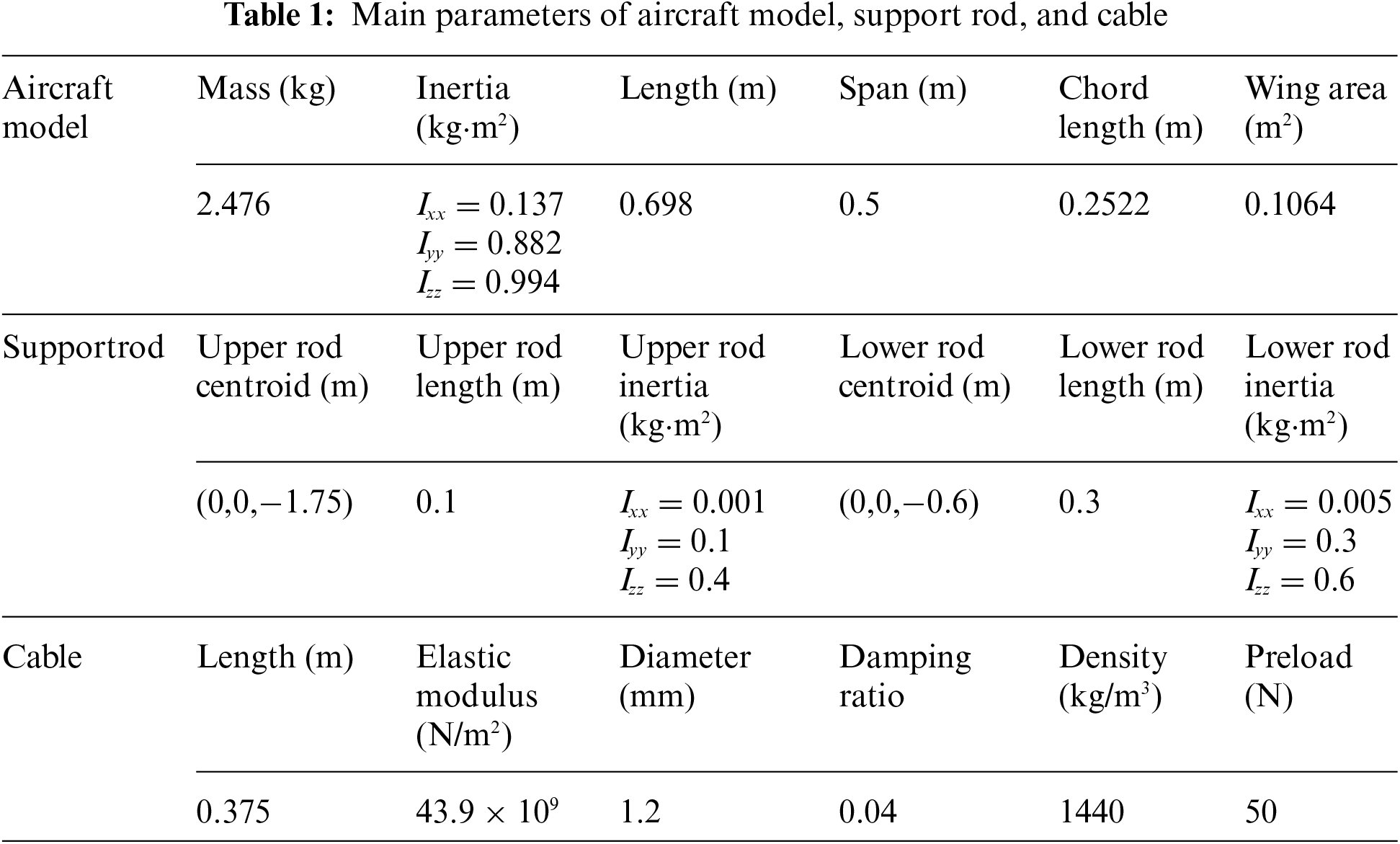
To verify the correctness of the above flight dynamics model and the feasibility of the support mechanism, the Simulink module in MATLAB was used to perform a simulation analysis. To analyze the influence of friction torque on the support mechanism and that of the constraints of the support mechanism on the motion of the model, the stability of the support mechanism was first investigated, and then three different working conditions were used for comparison: the model without friction torque (CDPR-VFT), the motion with friction torque (CDPR-VFT+F friction) under the support constraint, and the unconstrained motion of the model (three degrees of freedom (3DOF) unconstrained). The main parameters of the aircraft model, support rods, and cables are presented in Table 1.
6.1 Stability Analysis of Mathematical Models
First, the simulation was performed after initial trimming (trimming angle of 2.1°). Without controlling surface deflection and wind speed, the head-up pitch angle of the model was considered as 1°, and the initial preload force of the cable was 40 N to examine the variation of the model and the pitch support rod.
As shown in Fig. 10, the initial negative moment applied to the model decreased the pitch angle, the model headed downward, and the lower crossbar was subjected to a positive pitching moment, which increased the pitch angle. They oscillated back and forth in the equilibrium position, and their amplitude decayed continuously. The pitch angle of the model finally stabilized at 0.96°, indicating that the curve tendency is reasonable, and the mechanism is stable. The amplitude of the crossbar oscillation is large and is related to the cable preload force and rotational inertia.

Figure 10: CDPR-VFT mechanism oscillation simulation
The above results demonstrate that owing to the elastic damping of the cable, slight oscillations occur during the movement of the mechanism, but they quickly stabilize. If the cable is tightened by a moving pair in the screw assembly of the mechanism, the preload force of the cable can be increased to reduce this slight oscillation.
6.2 Analysis of Typical Longitudinal Manipulation Response
Owing to space limitations, only the typical longitudinal manipulation response of the CDPR-VFT was investigated in this study.
The typical longitudinal manipulation input signal was selected, that is, when the wind speed was stabilized at 20 m/s, the elevator step of 1° was input and the step point was at 10 s. The manipulation response of the elevator is depicted in Figs. 11–15.

Figure 11: Change in attack angle

Figure 12: Change in pitch angle

Figure 13: Change in pitch angular rate

Figure 14: Change in pitch angle

Figure 15: Displacement change of center of mass of model
6.2.1 Analysis of the Effect of Friction Moment
To analyze the influence of the frictional moment of the crossbar bearing on the mechanism of the support system, two cases of the support mechanism without and with frictional moment were selected for comparison.
The simulation results in Figs. 11–13 illustrate that the elevation of 1° results in a negative pure pitch moment and the model is in steady state at 3.12 s, following several back-and-forth oscillations. No roll or yaw motions for the model and cable-driven support mechanism are observed. The attack angle was equal to the pitch angle. The frictional moment had a damping effect on the pitch motion, and the damping decreased the attack angle and pitch angle by approximately 0.005°. Moreover, the damping decreased the peak of pitch rate, which was approximately 0.02°/s, indicating that the friction moment has little effect on the support mechanism.
6.2.2 Comparative Analysis with Unconstrained Rotation with Three Degrees of Freedom
To analyze the response characteristics of the entire support mechanism to the model, a simulation of unconstrained rotation with three degrees of freedom was introduced for comparison data to verify the correctness of the mechanism.
Fig. 14 illustrates that the cable-driven virtual flight support mechanism of the model designed in this study is consistent with the tendency of the simulation results of the unconstrained rotation with three degrees of freedom, which lags by approximately 0.04 s because of the effects of friction and cable elasticity.
6.2.3 Analysis of the Effect of Center of Mass Displacement
The variation in the center of mass displacement of the model under the longitudinal manipulation input is shown in Fig. 15.
Fig. 15 illustrates that the displacement of the center of mass of the model along the three axes is very small, and the maximum displacement along the X-direction of the nose is 0.01 mm. The amplitude of oscillation becomes gradually smaller, and finally reaches a stable state. The cable-driven VFT model support mechanism basically restrains the three translational degrees of freedom and releases the three rotational degrees of freedom, which meets the support requirements of the WTB-VFT model.
6.2.4 Analysis of the Effect of Cable Preload
The change in the preload of the different cables under the above longitudinal manipulation input is shown in Fig. 16.

Figure 16: Effects of different cable preloads on longitudinal control response
Because the tension change caused by the elastic deformation of the cable in this study was relatively small compared with the aerodynamic force and control torque, the effect of increasing the cable preload on the longitudinal control response was very small. Owing to the elasticity of the cable, the mechanism inevitably had a small translation, but this allowed for the translation requirements of the supporting mechanism of the VFT model because WTB-VFT focuses more on releasing the three rotational degrees of freedom of the model.
According to the dynamic similarity criterion [14], the model depicted in Fig. 17 was processed in this study, and an open-loop control experiment of pitching a single degree of freedom was conducted. The cross-section of the wind tunnel outlet was 600 mm × 600 mm and the wind speed was 10 m/s. The motion response process of the model was investigated to verify the feasibility of the mechanism shown in Fig. 18.

Figure 17: Principal prototype in wind tunnel test

Figure 18: Elevator open loop control test
After the model was trimmed, an elevator dual square-wave maneuver was performed to excite the short-period modal motion of the model. The initial pitch angle of model trim was −4.5°, and the elevator moved from 0° to the negative direction of the control surface (i.e., the positive direction of Δδe in the figure deflected to 10°). The model obtained the pitching moment of the head, and the pitching angle rose to approximately 22° with small amplitude oscillation. The elevator deflected to 14° in the positive direction of the control surface, and the model obtained the pitching moment of the lower head. The pitching angle decreased to approximately −12° and became stable after a small oscillation. Finally, the elevator returned to zero, the model obtained the pitching moment of the lift, and the pitching angle returned to near 0°. The dual square-wave maneuver was repeated three times, and the motion response state of the model remained basically the same.
Fig. 18 shows that the lift characteristics of the model are evident. The change in the model pitch angle obtained by deflecting the elevator in the negative direction of the control surface was considerably larger than that obtained by deflecting the elevator in the positive direction of the control surface. After each square-wave step maneuver, the pitch angle of the model oscillated slightly and tended to stabilize. This is due to the interaction between the inertia and air damping of the model, and the overall tendency is similar to that of typical longitudinal manipulation simulation results (see Fig. 12), verifying the feasibility of the CDPR-VFT mechanism.
In this study, CDPR-VFT was designed. Through mechanism design, dynamic modeling, simulation analysis, and experimental verification, the following conclusions were obtained:
1) The CDPR-VFT mechanism was designed according to the mechanism theory. Through the degree of freedom verification, it is proved that the mechanism can realize the free coupling and decoupling of the model with three rotational degrees of freedom and meet the requirements of the WTB-VFT model support;
2) Structural optimization and stability analysis of the CDPR-VFT were performed, proving that the optimized mechanical structure has good stability;
3) A mathematical model of the kinematics and dynamics of the cable-driven underconstrained, reconfigurable, passively driven mechanism was developed for the CDPR-VFT, which considers the cable elasticity and friction moment, on which the stiffness and stability criteria of the system are derived, and an example is provided herein. Finally, simulation and experimental methods were used to analyze the response of the model to typical longitudinal maneuvers in VFT. The results show that the CDPR-VFT model support mechanism has little effect on the motion of the vehicle model, which verifies the feasibility and validity of the mathematical model.
The CDPR-VFT developed in this study can provide conditions for conducting integrated research on aerodynamics/motion/control of aircraft models, exploring the mechanism of aerodynamics/motion coupling of aircraft models, identifying aerodynamic parameters of models, and providing a reference for designing cable-driven WTB-VFT models.
Funding Statement: The authors received no specific funding for this study.
Conflicts of Interest: The authors declare that they have no conflicts of interest to report regarding the present study.
References
1. Ratliff, C. L., Marquart, E. J. (1995). Bridging the gap between ground and flight tests: Virtual flight testing (VFT). 1st AIAA Aircraft Engineering, Technology, and Operations Congress, Los Angeles, CA. AIAA-95-3875. DOI 10.2514/6.1995-3875 [Google Scholar] [CrossRef]
2. Zhao, Z. L., Wu, J. Q., Li, H. (2016). Investigation of virtual flight testing technique based on 2.4 m transonic wind tunnel. Acta Aeronautica et Astronautica Sinica, 37(2), 504–512. DOI 10.7527/S1000-6893.2015.0196. [Google Scholar] [CrossRef]
3. Geber, T. G., Kell, Y. J., Lopez, J. (2000). Wind tunnel based virtual flight testing. 38th Aerospace Sciences Meeting & Exhibit, Reno, NV. AIAA-2000-0829. DOI 10.2514/6.2000-829. [Google Scholar] [CrossRef]
4. Magill, J. C., Cataldi, P., Morency, J. R., Hammer, D. X., Anderson, B. D. (2003). Design of a wire suspension system for dynamic testing in AEDC 16T. 41st Aerospace Sciences Meeting & Exhibit, pp. 1–11. Reno, Nevada. AIAA-452. DOI 10.2514/6.2003-452. [Google Scholar] [CrossRef]
5. Lawrence, F. C., Mills, B. H. (2002). Status update of the AEDC virtual flight testing development program. 40th AIAA Aerospace Sciences Meeting and Exhibit, Reno, NV. AIAA-2002-0168. DOI 10.2514/6.2002-168. [Google Scholar] [CrossRef]
6. Lowenberg, M. H., Kyle, H. L. (2002). Development of a pendulum support rig dynamic wind tunnel apparatus. AIAA Atmospheric Flight Mechanics Conference and Exhibit, Monterey, California. AIAA-2000-4879. DOI 10.2514/6.2002-4879. [Google Scholar] [CrossRef]
7. Davison, P. M. (2003). Development modelling and control of a multi-degree-of-freedom dynamic wind tunnel rig (Ph.D. Thesis). University of Bristol, England. [Google Scholar]
8. Gatto, A., Lowenberg, M. H. (2006). Evaluation of a three-degree-of-freedom test rig for stability derivative estimation. Journal of Aircraft, 43(6), 1747–1762. DOI 10.2514/1.19821. [Google Scholar] [CrossRef]
9. Pattinson, J., Lowenberg, M. H., Goman, M. G. (2013). Investigation of poststall pitch oscillations of an aircraft wind-tunnel model. Journal of Aircraft, 50(6), 1843–1855. DOI 10.2514/1.C032184. [Google Scholar] [CrossRef]
10. Pattinson, J., Lowenberg, M. H., Goman, M. G. (2003). Multi-degree-of-freedom wind-tunnel maneuver rig for dynamic simulation and aerodynamic model identification. Journal of Aircraft, 50(2), 551–566. DOI 10.2514/1.C031924. [Google Scholar] [CrossRef]
11. Pattinson, J. (2010). Development and evaluation of a wind tunnel manoeuvre rig (Ph.D. Thesis). University of Bristol, England. [Google Scholar]
12. Grishin, I., Khrabrov, A., Kolinko, A., Sidoryuk, M., Vyalkov, A. (2014). Wind tunnel investigation of critical flight regimes using dynamically scaled actively controlled model in 3 DOF gimbal. 29th Congress of the International Council of the Aeronautical Sciences, pp. 1–11. St.Petersburg, Russia. [Google Scholar]
13. Ignatyev, D. I. (2018). Neural network adaptive control of wing-rock motion of aircraft model mounted on three-degree-of-freedom dynamic rig in Wind Tunnel. Progress in Flight Dynamics, Guidance, Navigation, and Control, 10(3), 73–86. DOI 10.1051/eucass/201810073. [Google Scholar] [CrossRef]
14. Li, H. (2012). Study on the similarity criteria and simulation method of the wind tunnel based virtual flight testing (Ph.D. Thesis). China Aerodynamics Research and Development Center, Mianyan, China. [Google Scholar]
15. Guo, L. L., Zhu, M. H., Kong, P., Nie, B. W., Zhong, C. W. (2016). Analysis of dynamic characteristics between prototype aircraft and scaled-model of virtual flight test in wind tunnel. Acta Aeronautica et Astronautica Sinica, 37(8), 2583–2593. DOI 10.7527/S1000-6893.2015.0296. [Google Scholar] [CrossRef]
16. Guo, L. L., Zhu, M. H., Fu, H., Kong, P., Zhong, C. W. (2017). Modeling and simula-tion for a low speed wind tunnel virtual flight test rig. Acta Aerodynamica Sinica, 35(5), 708–717. DOI 10.7638/kqdlxxb-2017.0164. [Google Scholar] [CrossRef]
17. Guo, L. L., Zhu, M. H., Fu, H., Yang, H. S., Zhong, C. W. (2018). Theoretical analysis of research on aircraft spin characteristic in horizontal wind tunnel. Acta Aeronautica et Astronautica Sinica, 39(6), 122030. DOI 10.7527/S1000-6893.2018.22030. [Google Scholar] [CrossRef]
18. Cen, F., Nie, B. W., Liu, Z. T., Sun, H. S., Li, Q. (2017). Low speed wind tunnel free-flight test of powered sub-scale aircraft. Acta Aer-Onautica et Astronautica Sinica, 38(10), 121214. DOI 10.7527/S1000-6893.2017.121214. [Google Scholar] [CrossRef]
19. Cen, F., Nie, B. W., Liu, Z. T., Guo, L. L., Sun, H. S. et al. (2020). Wind tunnel model flight test technique for advanced fighter aircraft design. Acta Aeronautica et Astronautica Sinica, 41(6), 211–221. DOI 10.7527/S1000-6893.2019.23444. [Google Scholar] [CrossRef]
20. Cen, F., Li, Q., Liu, Z. T., Zhang, L., Jiang, Y. (2020). Post-stall flight dynamics of commercial transport aircraft configuration: A nonlinear bifurcation analysis and validation. Journal of Aerospace Engineering, 235(3), 368–384. DOI 10.1177/0954410020944085. [Google Scholar] [CrossRef]
21. Lv, G. N. (2009). Research on a flight dynamics and control in wind tunnel based virtual flight test (Master Thesis). Nanjing University of Aeronautics and Astronautics, Nanjing, China. [Google Scholar]
22. Wang, Z. A., Gong, Z., Chen, Y. L., Sun, M. W., Xu, J. F. (2020). Practical control implementation of tri-tiltRotor flying wing unmanned aerial vehicles based upon active disturbance rejection control. Journal of Aerospace Engineering, 234(4), 943–960. DOI 10.1177/0954410019886963. [Google Scholar] [CrossRef]
23. Shang, Z. M., Wu, J. L., Niu, Z. G., Bu, C. (2019). The wind tunnel virtual flight test of flying wing configuration aircraft model with the plasma actuation. Aeronautical Science & Technology, 30(9), 40–46. [Google Scholar]
24. Ji, Y. F., Lin, Q., Hu, Z. H., Peng, M. J., Wang, Y. Q. (2017). Research on feasibility of dynamic stability derivatives test of SDM with wire-driven parallel robot suspension system. Acta Aeronautica et Astronautica Sinica, 38(11), 121330. DOI 10.7527/S1000-6893.2017.121330. [Google Scholar] [CrossRef]
25. Ming, A., Higuchi, T. (1994). Study on multiple degree of freedom positioning mechanisms using wires (part 1Concept, design and control. International Journal of the Japan Society for Precision Engineering, 28(2), 131–138. [Google Scholar]
26. Wang, X. G., Lin, Q. (2018). Progress in wire-driven parallel suspension technologies in wind tunnel tests. Acta Aeronautica et Astronautica Sinica, 39(10), 22064. DOI 10.7527/S1000-6893.2018.22064. [Google Scholar] [CrossRef]
27. Abbasnejad, G., Carricato, M. (2015). Direct geometrico-static problem of underconstrained cable-driven parallel robots with n cables. IEEE Transactions on Robotics, 31(2), 468–478. DOI 10.1109/TRO.2015.2393173. [Google Scholar] [CrossRef]
28. Mottola, G., Gosselin, C., Carricato, C. (2019). Dynamically feasible motions of a class of purely-translational cable-suspended parallel robots. Mechanism and Machine Theory, 132(1), 193–206. DOI 10.1016/j.mechmachtheory.2018.10.017. [Google Scholar] [CrossRef]
29. Carricato, M., Merlet, J. P. (2014). Direct geometrico-static problem of under-constrained cable-driven parallel robots with three cables. 2011 IEEE International Conference on Robotics and Automation, pp. 3011–3017. Shanghai, China. DOI 10.1109/icra.2011.5979762. [Google Scholar] [CrossRef]
30. Huang, Z., Li, Q. C., Ding, H. F. (2013). Theory of parallel mechanisms. Germany: Mechanisms and Machine Science. [Google Scholar]
31. Huang, Z., Zeng, D. X. (2016). Freedom calculation of mechanism: Principle and method. Beijing, China: Higher Education Press. [Google Scholar]
32. Yang, W., Wang, J. F., Wu, J. L. (2018). Research on virtual flight test technology of aerodynamic/motion control coupling for high maneuverable fighter in low speed wind tunnel. The 10th National Conference on Fluid Mechanics, pp. 132–139. Hangzhou, China. [Google Scholar]
33. Ahmadizadeh, M., Shafei, A. M., Fooladi, M. (2021). Dynamic modeling of closed-chain robotic manipulators in the presence of frictional dynamic forces: A planar case. Mechanics Based Design of Structures and Machines, 1–21. DOI 10.1080/15397734.2021.1966304. [Google Scholar] [CrossRef]
34. Ahmadizadeh, M., Shafei, A. M., Fooladi, M. (2021). Dynamic analysis of multiple inclined and frictional impact-contacts in multi-branch robotic systems. Applied Mathematical Modelling, 91, 24–42. DOI 10.1016/j.apm.2020.09.017. [Google Scholar] [CrossRef]
35. Ahmadizadeh, M., Shafei, A. M., Jafari, R. (2021). Frictional impact-contacts in multiple flexible links. International Journal of Structural Stability and Dynamics, 21(6), 2150075. DOI 10.1142/S0219455421500759. [Google Scholar] [CrossRef]
36. Wu, S. T. (2018). Flight control system. Beijing: Beihang University Press. [Google Scholar]
37. Pan, J. X., Lin, Q., Wu, H. S., Zhou, F. G., Wang, X. G. (2021). Comparative experimental study on wind tunnel based on WDPR-8 and machetes tail support. Journal of Beijing University of Aeronautics and Astronautics, 47(5), 1038–1048. DOI 10.13700/j.bh.1001-5965.2020.0124. [Google Scholar] [CrossRef]
38. Carricato, M., Merlet, J. P. (2010). Geometrico-static analysis of under-constrained cable-driven parallel robots. In: Advances in robot kinematics: Motion in man and machine, pp. 309–319. Dordrecht: Springer. DOI 10.1007/978-90-481-9262-5. [Google Scholar] [CrossRef]
Cite This Article
 Copyright © 2023 The Author(s). Published by Tech Science Press.
This work is licensed under a Creative Commons Attribution 4.0 International License , which permits unrestricted use, distribution, and reproduction in any medium, provided the original work is properly cited.
 Downloads
 Citation Tools