
 Submit a Paper
 Propose a Special lssue
 Open Access
ARTICLE
Investigation on the Folding Mode and Deployment Process of an Inflatable Boarding Platform for the Marine Emergency Evacuation System
College of Mechanical and Electrical Engineering, Harbin Engineering University, Harbin, 150001, China
* Corresponding Author: Fankai Kong. Email:
(This article belongs to the Special Issue: Computer Modeling in Ocean Engineering Structure and Mechanical Equipment)
Computer Modeling in Engineering & Sciences 2023, 135(1), 483-510. https://doi.org/10.32604/cmes.2022.021083
Received 26 December 2021; Accepted 12 May 2022; Issue published 29 September 2022
 View Full Text
 Download PDF
Abstract
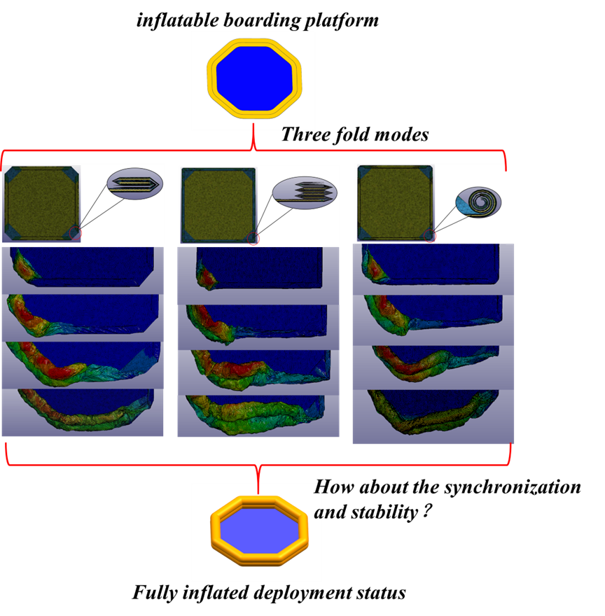
The different folding and storage forms of an inflatable boarding platform will have a direct impact on the deployment effect of the marine emergency evacuation system. This paper proposes different folding and storage methods for an inflatable boarding platform in a marine emergency evacuation system. According to the difference between the fold line and the fold direction, the numerical models of a boarding platform with partial fold, “Z” type fold and inner spiral fold are established. The platform models with three folding modes are simulated by numerical simulation. According to the numerical results of the inflation process, the displacement changes of the inflatable membrane and the surface characteristics of the model are compared and analyzed, and the synchronization of the deployment process of the upper and lower airbags in three folding forms is studied. The deployment characteristics of different folding inflatable boarding platforms in different stages are analyzed. The numerical results are of great reference value to the folding and releasing process of an inflatable boarding platform and its practical design as well as its application in the evacuation system.Graphic Abstract
Keywords
An offshore platform is huge in volume, complex in structure and high in distance from the deck to the sea level. In case of a disaster, due to the lack of evacuation time, complex rescue environment and other factors, it is likely to cause casualties. Therefore, how to rescue personnel safely and effectively in the event of an offshore platform accident is an urgent problem [1,2].
The marine emergency evacuation system is favored by many scientific research institutions because of its high efficiency and reliability [3]. The offshore emergency evacuation system is a kind of comprehensive offshore lifesaving equipment composed of an evacuation box module, a release and recovery module, an evacuation slide module, and a water lifesaving device module [4], as shown in Fig. 1. This evacuation system has the advantages of small occupied space, excellent storage characteristics, adaptability to extreme sea conditions, and the length of the slide can be automatically adjusted with the evacuation height. After the relevant operators release and deploy the evacuation system, the people in distress on the platform can safely and effectively evacuate to the safe area through the evacuation slide, the boarding platform and the life raft [5].
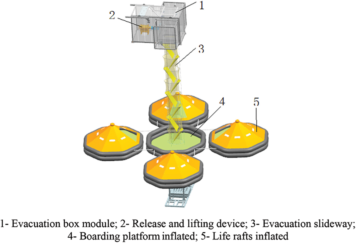
Figure 1: Marine emergency evacuation system in deployment state
The main functions of a boarding platform for the maritime emergency evacuation system are: (1) buffering. The evacuees glide from the offshore platform to the landing platform through the slideway module of the evacuation system, contact with the bottom of the landing platform and complete deceleration. (2) Accommodate evacuees. Due to the fast sliding speed of evacuees and the slow speed of transferring to life rafts, some people will stay on the boarding platform during the evacuation process, so the center of an inflatable boarding platform provides space for more than one person. (3) Connect liferafts and transfer evacuees. The boarding platform is an octagonal structure, which can fix the entrance position of liferafts at any side or connect with multiple liferafts, further accelerating the evacuation efficiency.
At present, the research direction of the marine emergency evacuation system is mainly the release and recovery function of the winch, the stress analysis of the rope net slide, the evacuation efficiency of personnel, etc. [6], but there are few studies on the performance of the water rescue device module. Through the analysis of many manufacturers of the maritime emergency evacuation and rescue exercise video system experiment, it was found that there are some problems of deployment in the water rescue device module, such as the structure around the air inlet is stuck and the air intake process is blocked, or one corner of the boarding platform interferes with the evacuation slide module and cannot fully unfold [7].
The boarding platform is essentially an inflatable membrane structure. The inflatable membrane structure is mainly divided into single-layer, double-layer and air rib types. Due to its stable geometry and positive Gaussian curvature, it is currently mainly used in automobile airbags, aircraft inflatable slides, aircraft landing airbags and other related fields [8].
Cadogan et al. [9] developed a folding method that folds inward to enable the Mars Pathfinder's landing airbags to deploy rapidly without entanglement. Petit et al. [10] used Excel and MATLAB to mesh and fold the airbag on the front of the car, and compared the simulation results of airbag release with the experimental results, which proved that the method could match the test results of the first 60 ms. Zhang et al. [11] designed a mapping mesh auto flattening algorithm by using the initial measurement method, and obtained the element geometry transformation matrix of airbag by using the computer graphics theory. This algorithm greatly improves the efficiency and accuracy of airbag modeling. Ritmeijer et al. [12] proposed a Gasflow analysis method for fabric layer airbags, and analyzed and predicted the folding and unfolding process of airbags. This method can simulate the gas flow better, especially in the initial inflation stage. Blümcke et al. [13] conducted numerical and experimental studies on the unfolding state of the knee airbag with real gas flow phenomena, and simulated the folding mode of the airbag with the automated process of ESI SimFolder. On the basis of effective CAE simulation, Zhang et al. [14] discussed the optimization analysis of curtain airbags under different diffuser parameters, mass flow rate of inflator and airbag folding mode. Wei et al. [15] analyzed the interaction between gas and membrane during the expansion of inflatable membrane structure by using the finite volume method, established the finite volume model of the gas flow field in the folded membrane tube, and obtained the relationship between the pressure in the membrane and the inlet flow. Through the real-time quasi-static expansion experiment, Radek et al. [16] used the particle method and ALE method to carry out a numerical study on the expansion process of thin single section inflatable membrane, and compared the results of the two algorithms. Yu et al. [17] used the control volume method to simulate the inflation process of Z-type folded space inflatable structure, control the different deployment constraints, and determine the effective constraint range of the structure. Aiming at the inflatable structure of flexible fabric, Zhao et al. [18] used the method of motion folding to establish the folding model of inflatable aerodynamic reducer which cannot be established by the existing folding method, and then realized multi-dimensional folding. In the above cases, the experimental objects are mostly small airbags, which are generally simple in shape, have a small model airway volume, and have a short inflation time. The numerical folding simulation method used in the literature is single, and there is no comparative optimization analysis of different numerical folding methods for the same model.
In view of the shortcomings of the above existing research, this paper analyzes and studies the inflatable folding mode and deployment process of an inflatable boarding platform structure in the large-scale offshore emergency evacuation system. Firstly, the different folding methods of an inflatable landing platform are introduced, and the models of partial folding form, “Z” type folding form and inner spiral folding form are established, respectively. Then, by using the CPM inflation numerical method, LS-DYNA is used to calculate the inflation expansion of the landing platform model under different folding states, and the model states, such as the displacement change of the inflation membrane and the surface characteristics, are compared and analyzed. Finally, the displacement state of the mesh unit on the surface of the landing platform model in three folding modes is compared, and the synchronization analysis of the inflation process of the upper and lower airbags in the folding state is completed. This study provides theoretical support for the offshore application of large-scale inflatable membrane structures.
2 Folding Mode of the Boarding Platform for Marine Emergency Evacuation System
2.1 Folding Mode of the Inflatable Boarding Platform
In general, the folding form of airbag is mainly divided into direct flat folding, roll-up folding and fold-in folding [19]. As shown in Fig. 2.
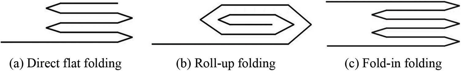
Figure 2: Schematic diagram of airbag folding mode
Depending on the shape of the fold line position, folding forms can be divided into thin folding, tuck folding, thick folding and spiral folding [20]. As shown in Fig. 3.
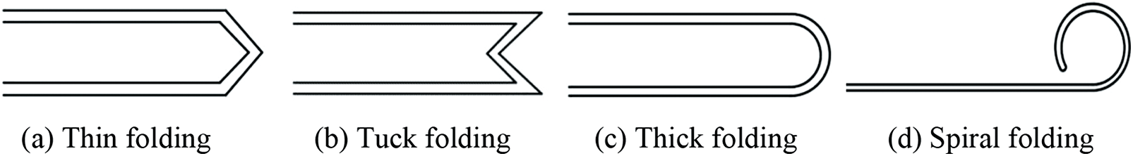
Figure 3: Schematic diagram of fold line type
Thin folding is the main way of airbag folding. It is simple to handle the fold line. Only one unit of the connecting line can be used as the fold line. The number of units at the fold line is small. However, due to the large angle of rotation, it may lead to problems such as unit penetration, deformation and crossing at the fold line position. In order to solve this kind of problem, the mesh at the fold line needs to be further processed. In the pre-processing, the scale value of Folder can control the mesh situation at the fold line. The state of the fold line at different scale values is shown in Fig. 4, and the default scale value of the system is 1 [21].
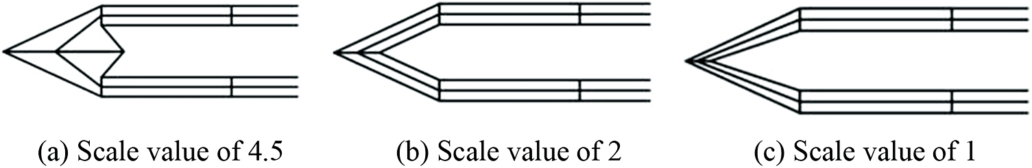
Figure 4: Fold line state with different scale values
The folding mode of the boarding platform directly affects its deploying process. In order to verify the inflatable unfolding characteristics of the boarding platform under different folding conditions, three different folding modes are carried out for the boarding platform model, which are partial fold, “Z” type fold and inner spiral fold.
The status of the boarding platform before and after inflation is shown in Fig. 5.
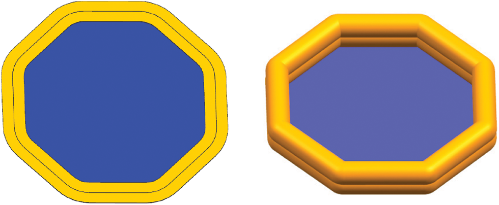
Figure 5: The model of before (left) and after (right) inflation
2.2 Establishment of Numerical Model for the Boarding Platform
The static tile model of the boarding platform is composed of upper airbag, airbag connecting belt, lower airbag and bottom cloth. Due to the large size of the model, the mesh density of the connection between the upper and lower layers of the airbag and the connection between the two airbags was 0.01 m, and the mesh density of the other parts was 0.05 m. The schematic diagram after mesh partition is shown in Fig. 6. The air intake units of two airbags were set independently on the same side without interference with the surface grids of the airbags, and the number of grids was 406,529. The material density of the model was 1250 kg/m3, the elastic modulus was 5.0 × 10⁹ Pa, and the Poisson's ratio was 0.35. The type of air source was WGA108–1.5–15. The volume parameter of compressed carbon dioxide gas was 5 litre and the pressure was 15 MPa.
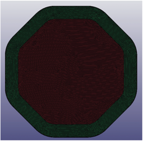
Figure 6: Airbag model of the boarding platform
The solver was LS-DYNA and LS-PrePost software was used for preprocessing. The keyword setting was (*AIRBAG_HYBRID_ID). When setting the working environment of the airbag, the influence of atmospheric pressure was taken into account on the outer surface of the airbag. The keyword setting card is shown in Fig. 7. In addition, the position of the air inlet was set. After the air inlet part was established in the model, the point of the air inlet unit was selected in the keyword card NID to simulate the position of the air inlet. Set the solution time to 7 s, DT was set to 0 and NPLTC to 150 in BINARY-D3PLOT.
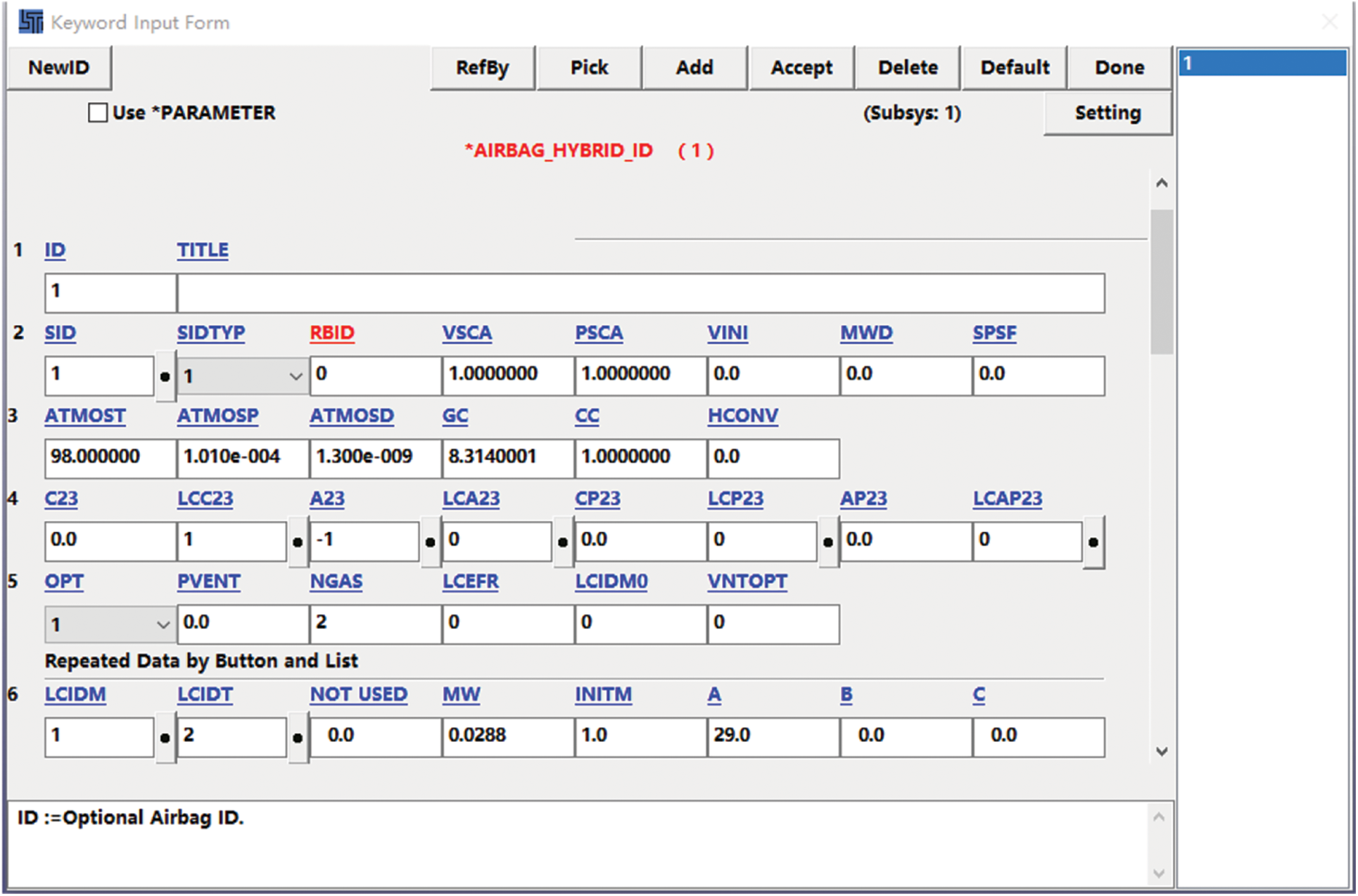
Figure 7: Airbag model of the boarding platform
2.3 Model Calculation of the Inflatable Boarding Platform
After solving by LS-DYNA, LS-PrePost software was used for post-processing to extract the d3plot result file, and the contours of displacement were obtained as shown in Fig. 8.
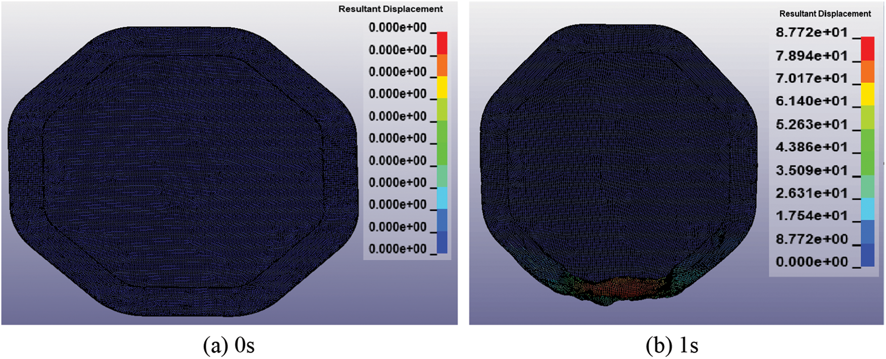
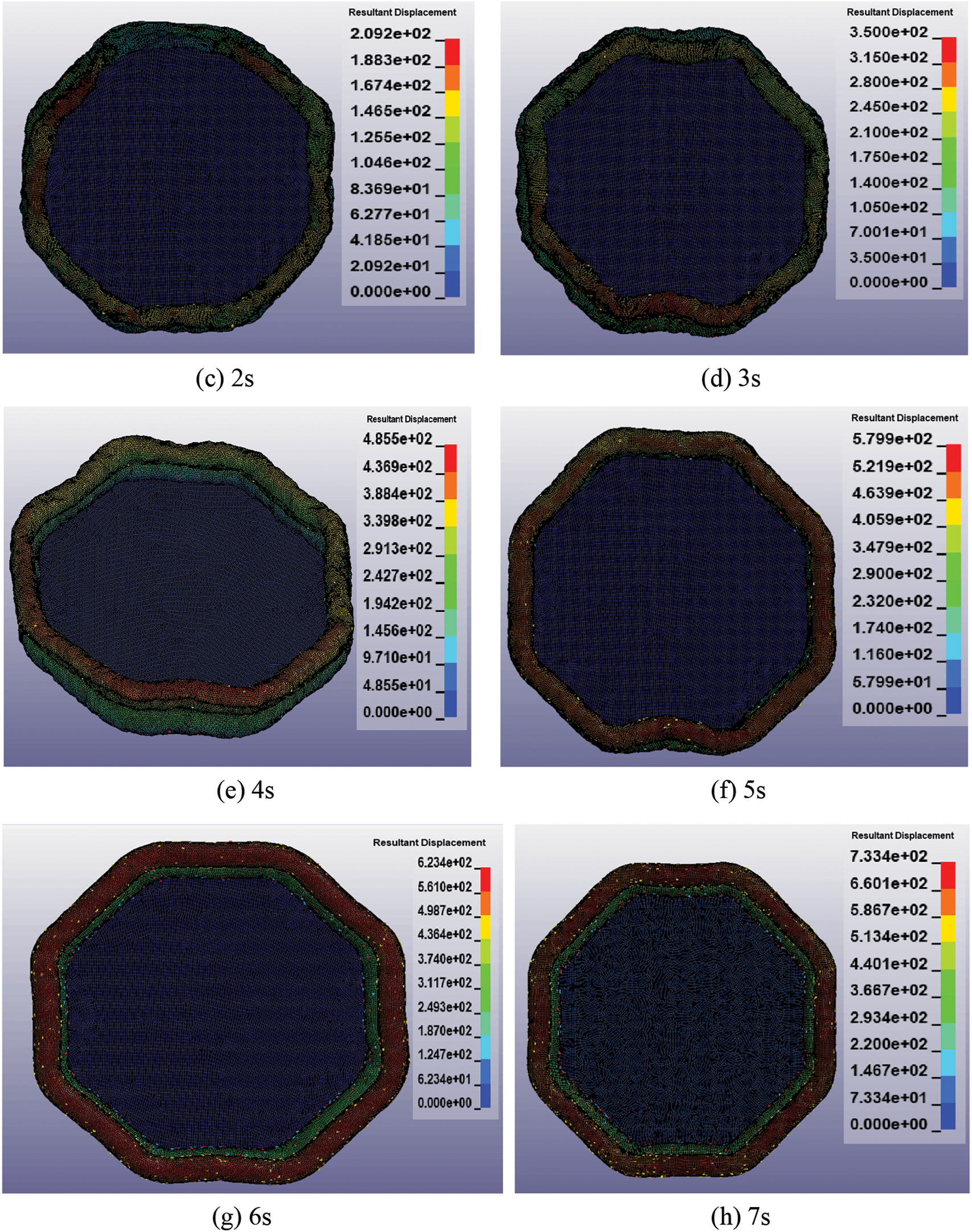
Figure 8: Airbag model of the boarding platform
Fig. 8a shows the state when the boarding platform was not inflated.
Fig. 8b shows that the gas was sprayed from the air inlet into the bag, and it could be observed that the displacement of the grid cells near the air inlet rose rapidly to the extreme value. Because the airbag is circular, the flow of air from the left and right sides of the air inlet to the depth of the airbag has a certain degree of synchronization. At the same time, as the airbag model is large and the airway is long, the flow characteristics of the gas can be observed. In the initial stage of inflating, the end is too far away from the air inlet and there is no inflating expansion phenomenon temporarily. At this time, the upper and lower surfaces of the airbag at this side were still in contact, presenting an unseparated state.
Fig. 8c represents the phenomenon that the displacement of the grid element increased rapidly when the gas from the air inlets met each other and passed through the left and right airways. At this point, the gas could flow completely inside the annular airbag, and the upper and lower surfaces of the airbag had been completely separated.
Fig. 8d shows that the surface of the airbag was in a relaxed state, at which time it can still be seen that the gas flows in the airway. At the same time, the lower surface of the upper airbag and the upper surface of the lower airbag pulled each other, and showed an irregular beating state.
Fig. 8e shows that the lower airbag had basically inflated to a state without folds, while the upper airbag still had some folds, reflecting the asynchronism of the interaction between the two airbags. Meanwhile, it could be seen that the gas leaking from the surface of the airbag was obvious at this stage. At this time, the shape state near the air inlet was obvious, but the far end had not got the shape.
Fig. 8f shows that the upper airbag gradually presented an octagonal shape and was full of air. Part of the corner of the lower airbag was not filled, and the leakage gas of the airbag gradually increased.
Fig. 8g shows that the surface of the upper and lower airbags was relatively smooth, without wrinkles, and each angle had been basically formed, while some edges were still in the state of inward bending.
Fig. 8h represents the completion of inflating process of the boarding platform.
According to the requirements of “the international lifesaving apparatus rules”, namely msc48 (66), the size of the marine lifesaving device with a loading capacity of 35 people is 3600 mm×3600 mm after the boarding platform is inflated. The folding idea of the boarding platform is as follows: lay the uninflated boarding platform on the XOY plane, as shown in Fig. 9. When folding the boarding platform, it is necessary to consider the storage of steel ring slideway above the center of the platform and the arrangement of counterweight below. When folding, it is necessary to consider the air inlet facing outwards, and it is not allowed to draw part of the air inlet into the folded airbag. Therefore, fold along the X-axis and Y-axis, i.e., A-edge Y + direction, C-edge X- direction, E-edge Y- direction, G-edge X + direction, and the other four sides follow the fold line for partial folding. The air inlets of the upper and lower airbags are arranged in the center of side H, and the air inlets are not involved in folding.
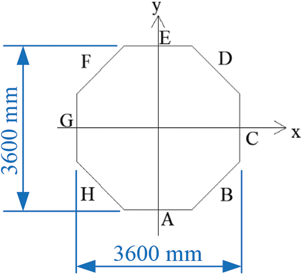
Figure 9: Schematic diagram of the tiled boarding platform
For the folding processing of the inflatable boarding platform, the PRIMER preprocessing module in OASYS software is used. This software can output K files, adapt to LS-DYNA solver, and further set in ls-prepost software. There are three kinds of folding methods for the boarding platform: partial folding, “Z” type folding and inner spiral folding.
There are many folding processes in partial folding. Now take the folding of edge A in Y + direction as an example to carry out the folding process, as shown in Fig. 10. (a) Considering the interface between the boarding platform and the offshore emergency evacuation system, the first fold line is determined to be 1400 mm away from the center point, the type of fold line is thin fold, and the direction is reverse. (b) The second fold line is 1100 mm away from the center point. The type of fold line is thin fold, and the direction is reverse.
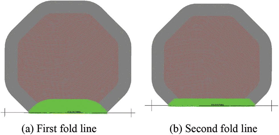
Figure 10: Partial folding operation for side A of the boarding platform
Fold the edge C along the X-direction, edge E in the Y-direction, and edge G in the X + direction as described above. After folding, import the boarding platform model into LS-Prepost for preprocessing of CPM method, as shown in Fig. 11. In this way, the number of layers on the folded airbag surface will increase with each additional folding. Therefore, it is necessary to refine the mesh at the fold line of the upper and lower airbag to avoid mesh destruction.
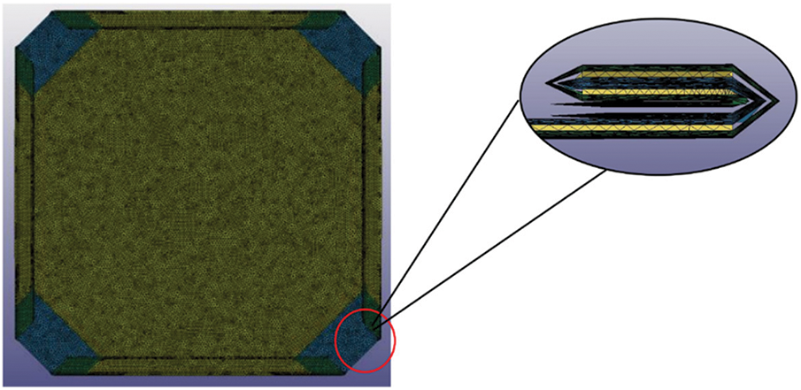
Figure 11: The partial folded boarding platform model
The “Z” type folding also takes the edge A along the Y + direction as an example to carry out the folding process, as shown in Fig. 12. (1) The first fold line is 1200 mm from the center. The type of fold line is thin fold, and the direction is reverse. (2) The second line is 1000 mm from the center, and the line type is thin fold. Select direction as forward. (3) The third line is 1200 mm from the center. The line type is thin fold, and the direction is reverse. (4) The fourth line is 1000 mm from the center, and the line type is thin fold. Select direction as forward. (5) The fifth line is 1200 mm away from the center. The line type is thin fold, and the direction is reverse. (6) The sixth line is 1000 mm from the center, and the line type is thin fold. Select direction as forward.
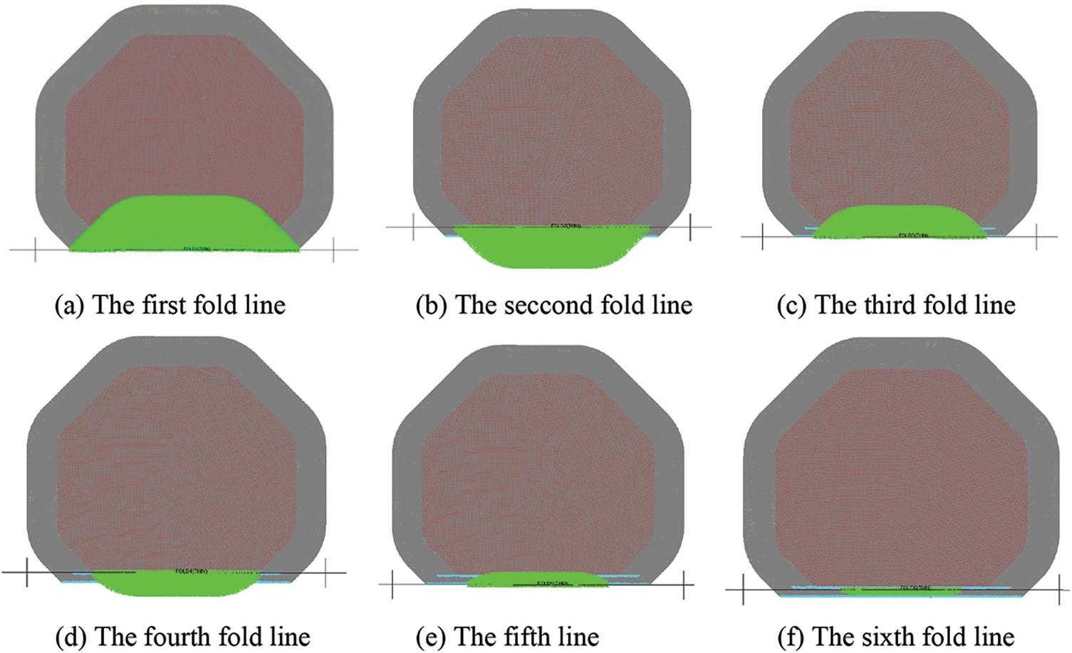
Figure 12: “Z” type folding operation for side A of the boarding platform
Fold the edge C along the X-direction, edge E in the Y-direction, and edge G in the X + direction according to the above methods. After folding, the boarding platform model is imported into LS-Prepost for the preprocessing of CPM method, as shown in Fig. 13. This folding method will not increase the number of layers on the surface of the airbag to be addressed, but it also needs to deal with the mesh problem at the fold line.
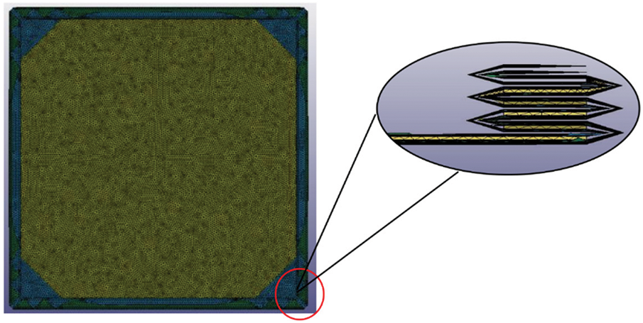
Figure 13: The “Z” type folded boarding platform model
Take the folding of edge A along the Y + direction as an example to perform the folding process of the inner spiral folding, as shown in Fig. 14. Only one “fold line” needs to be set for the inner spiral folding. The fold line in this way is different from the two mentioned above. It is not the dividing line left by the rotation of multiple groups of meshes, but the central axis rotating into multiple circles. Set the fold line distance from the center 1100 mm, the polyline type spiral fold, and select the direction as reverse.
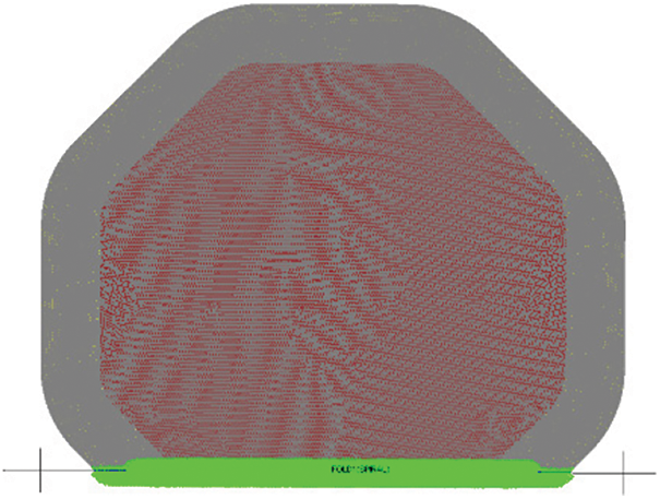
Figure 14: Inner spiral folding operation for side A of the boarding platform
Fold edge C along the X-direction, edge E in the Y-direction and edge G in the X + direction according to the above method. After folding, import the boarding platform model into LS-Prepost for preprocessing of CPM method, as shown in Fig. 15. In this way, because of the circular fold, the degree of mesh damage is low, and the mesh problem to be dealt with is less.
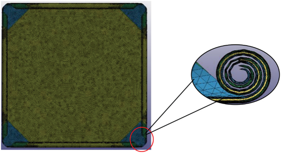
Figure 15: The inner spiral folded boarding platform model
To sum up, three different forms of folding are carried out for the boarding platform, and then the numerical calculation of CPM inflation deployment is completed for the three models.
3 Numerical Calculation of Inflation Process for Folding Model of the Boarding Platform
In order to better observe the effect of folding mode on the deployment of the boarding platform, four mesh units are selected as reference points to analyze the inflation process of the boarding platform. The selection principles of the four units are as follows: to facilitate observation, select from the upper surface of the airbag; select from the center of each folded edge; the selected unit can achieve the maximum displacement span when the airbag is inflated. The positions of the four selected units and the inflatable boarding platform are shown in Fig. 16. When folding, the four units are all folded between multiple airbag surfaces, which cannot be clearly marked in the folded state. The unit on side A is numbered S129453, the cell on side C is numbered S43243, the cell on side E is numbered S48413, and the number of side G unit is S132455.
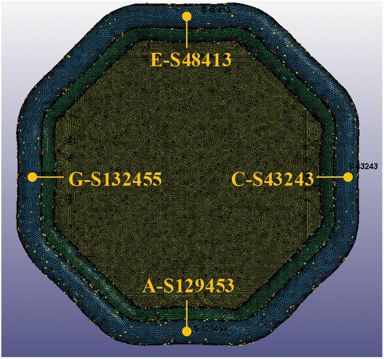
Figure 16: Schematic diagram of the positions of the four selected units when the landing platform is inflated
3.1 Inflatable Deployment of the Partial Folding Boarding Platform
Set the CPM method for the partial folded boarding platforms. After solving through LS-DYNA, check the corresponding result d3plot result file in LS-PrePost. The displacement nephogram is shown in Fig. 17. Because the deployment efficiency of different folding modes is different, the screenshots of different stages of airbag inflation deployment are compared.
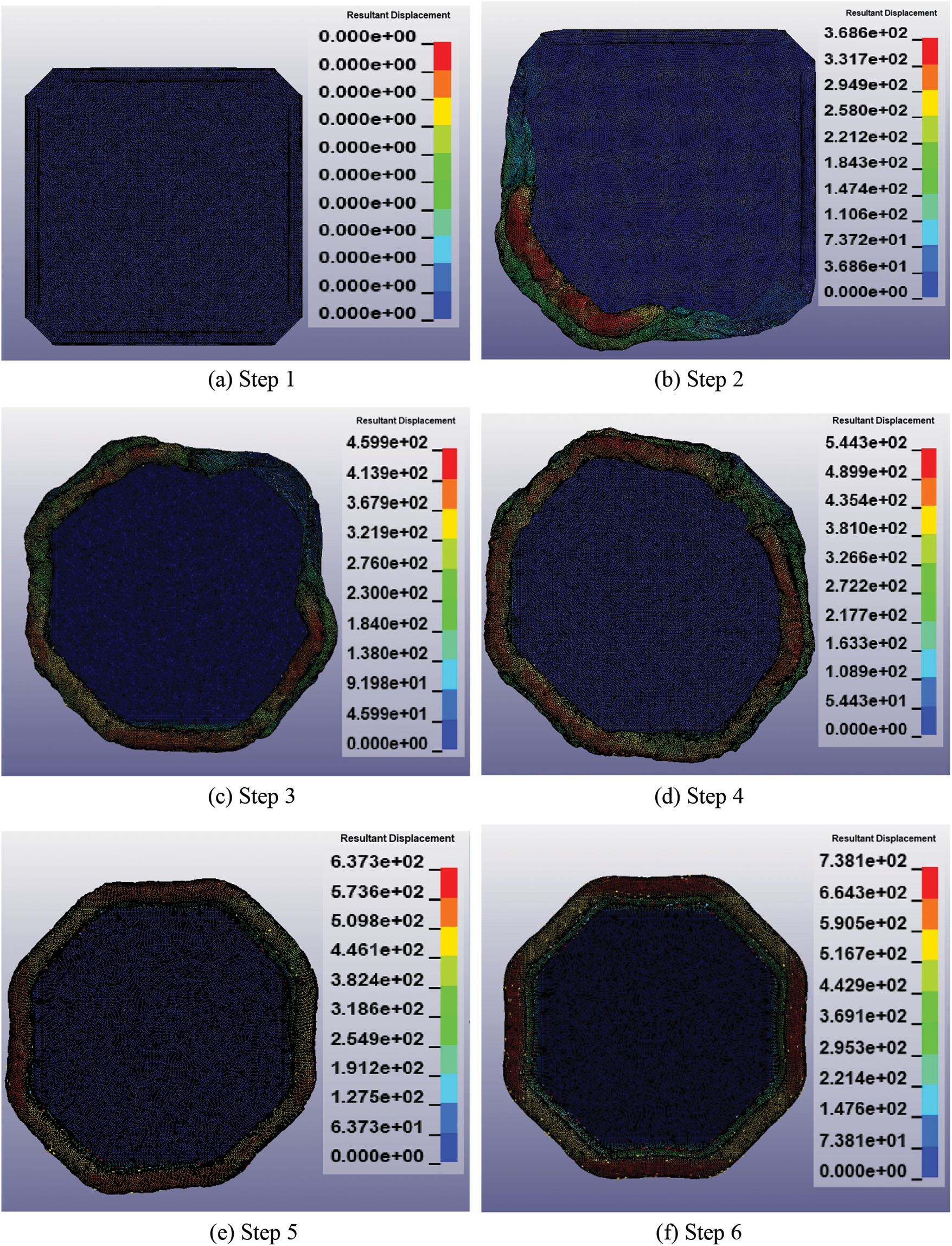
Figure 17: Displacement nephogram of the partial folding boarding platform during inflation
The Fig. 17a shows that the partial folded boarding platform is not inflated. At this time, the surfaces of the airbag are close to each other, and the volume in the airway is 0.
The Fig. 17b shows the initial stage of inflation. Since the air intlets of the two airbags are arranged on the side H of the airbag, the H-side has the priority of inflation expansion to a certain extent, and the airflow flows from the left and right sides to the distal side, and the folded edges A and G close to the H-side follow the expansion. As the gas particles impinged forward, the folded edges were first flipped to push the folded airbag surfaces outward.
The Fig. 17c shows that the C and E sides are overturned due to the effect of air flow. There are some ups and downs on side D due to the expansion and turnover of the airbag surface, but it is still in the folded state. At this time, the upper and lower surfaces of the four folded sides of the airbag have been separated, and the gas has flowed into the seven sides of the airbag. The movement displacement of A, G and H is further enhanced.
Fig. 17d shows that the air completely penetrates the air passage, and the upper and lower surfaces of the airbag are separated. At this time, the airbag completely breaks through the folding shape through the propulsion of the air flow. However, due to the small air flow, the airbag is still in a soft state, and the overall surface of the airbag has not yet reached the shape requirements of the surface. Further inflation can make the overall surface of the airbag expand outwards, eliminate wrinkles and improve the stiffness of the airbag. Because the mesh units on the surface of the airbag are all in contact with the charged gas particles, there is slight air leakage on the surface of the airbag.
Fig. 17e shows that there is no obvious wrinkle on the surface of the airbag, and the octagonal outline is initially formed. However, it can be seen that some of the 8 sides of the airbag are full and some are relatively loose, so it is necessary to continue to inflate to make the air flow push the airbag surface to the designated position. In this stage, the movement process of airbag is mainly to inflate each side into a straight line shape to eliminate the slack state of its inner bend. When all sides are in a straight line state, the shaping stage is completed and the airbag surface is in a fully unfold state.
Fig. 17f shows that the airbag inflation and deployment process is completed, and the airbag is in full state. After continuous inflation, the shape of the airbag surface will not change greatly, and the displacement of each mesh unit will remain basically the same. If the inflation is continued, the hardness of the airbag of the boarding platform will be improved.
Taking the folded part of side A as an example, the initial inflating stage is shown in Fig. 18a, and the further inflating and flip process of the airbag is shown in Figs. 18b–18d.
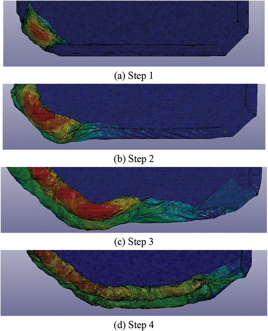
Figure 18: Displacement nephogram of inflatable deployment at side A of the partial folding boarding platform
Fig. 18a shows that in the initial inflation stage, a large amount of gas is gathered at the air inlet, ready to act on the folded part, at this time, there is a small gas residence time compared with the unfolded boarding platform.
Fig. 18b shows the initial action of the gas on the folded part. When the air flows, the particles impact the surface of the airbag and cause the airbag to turn over. Due to the effect of the airbag fabric material, the far position of the folded part also overturns partially, resulting in a small amount of displacement change, which is not affected by the air particles.
Fig. 18c shows the gas flowing to the middle of side A. It can be found that the gas on the left side has overturned the folded airbag. Due to the large amount of gas, it can be found that the surface displacement of airbag is large. Although the airbag at the forward end of the particle has undergone a large displacement change, it is still in a flipped state. For the right side area where the particles do not reach, there is a small amount of displacement change in the airbag.
Fig. 18d shows that the gas flow completely expands the folded part at A from the folded state, while the folded part at C is not affected temporarily. After further inflation, it will be found that the overturning and unfolding state at C is the same as that at A.
The four mesh units are analyzed, and their displacement-time images are compared to analyze the inflatable expansion characteristics of the partial folding boarding platform. The displacement images of the four mesh units are shown in Fig. 19. Among them, the Z-direction motion displacement curve of S129453 unit is z1, that of S132455 unit is z2, that of S48413 unit is z3, and that of S43243 unit is z4.
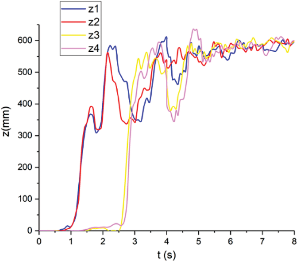
Figure 19: Displacement comparison of mesh units in different positions
It can be seen from the image that when the gas is inflated for 0 s, there is no displacement change due to the distance between the edge of the four units and the air inlet. At 0.6 s, the displacement of the selected mesh unit on the edge of A and G begins to increase. In this stage, when the gas flows, it drives the airbag to turn over, which causes a small amount of displacement changes in the two units. At this time, the gas particles do not act on the unit. At 1 s, the Z-direction displacement of S129453 and S132455 began to increase rapidly, and reached the peak value at 2.1 s and 2.2 s, respectively. At this time, due to the lack of gas and gas flow in the airbag, the airbag is still in a relaxed state, and the two units cannot maintain a stable position, so it will drop. At 2.9 s, the displacements of the mesh units on the C and E sides begin to change and reach the peak value at 4.2 s. After that, the surface of the airbag enters the wrinkle elimination stage and the shaping stage. Finally, the Z-direction displacement of the four units converges to 600 mm.
3.2 Inflatable Deployment of the “Z” Type Folding Boarding Platform
Set the CPM method for the “Z” type folded boarding platforms. After solving through LS-DYNA, check the corresponding result d3plot result file in LS-PrePost. The displacement nephogram is shown in Fig. 20.
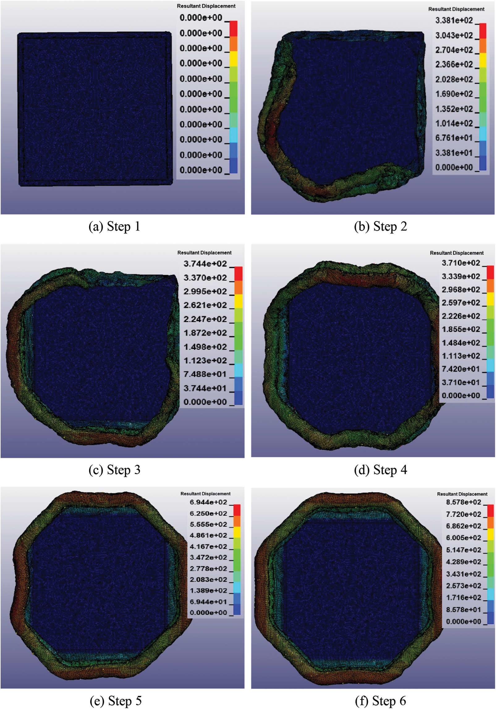
Figure 20: Displacement nephogram of the “Z” type folding boarding platform during inflation
The Fig. 20a shows that the “Z” type folded boarding platform is not inflated.
Fig. 20b shows the gas flow to side A and side G, which is different from the unfolding of partial folding type, where the mesh unit does not overturn, but directly unfolds outward. In the initial deployment, when breaking through the accumulation state, the unfolding motion of the “Z” type folding is relatively gentle, and the displacement of the whole airbag does not change dramatically. In this stage, we can see the flow direction of the air flow and the flow of the gas gathered at the H side near the air inlet at the beginning, which leads to the largest displacement of the mesh unit area at the A and G sides. The gas will continue to move forward along the airway. Due to the pull of fabric on the airbag surface, the folded airbag surface will be driven by the initially deployed airbag surface, which will produce partial displacement. However, this displacement change is not caused by the support of gas flow, but by the material characteristics of the airbag surface.
Fig. 20c shows that the gas flows to the C and E sides, and the folded airbag surface in this phase is similar to Fig. 20b in the deployment process, and the gas flow will further move forward.
Fig. 20d shows that the air flow inside the annular airbag is through, at this time, the upper surface and the lower surface of the two airbags are completely separated. It can be seen that the displacement of the mesh unit near the D sides is larger, that is, there are more gases here. At this time, the airbag is relatively loose, and there are many folds on all surfaces. The airbag is not fully opened, and it can be seen that each side has a certain angle of inclination.
Fig. 20e shows the shape fixing stage of the airbag. At this time, the airbag has initially formed an octagonal state, and each corner of the airbag has basically formed. However, there are still several sides inclined and bent inward. It is necessary to continue to inflate, so that the edge that does not reach the expected position continues to expand outward.
Fig. 20f shows that the inflation state is completed, and reinflation will not change the shape of the airbag, but only increase the hardness of the boarding platform.
Take the folding part of side A as an example, and its inflation initial stage is shown in Fig. 21, to further analyze the inflation process of airbag.
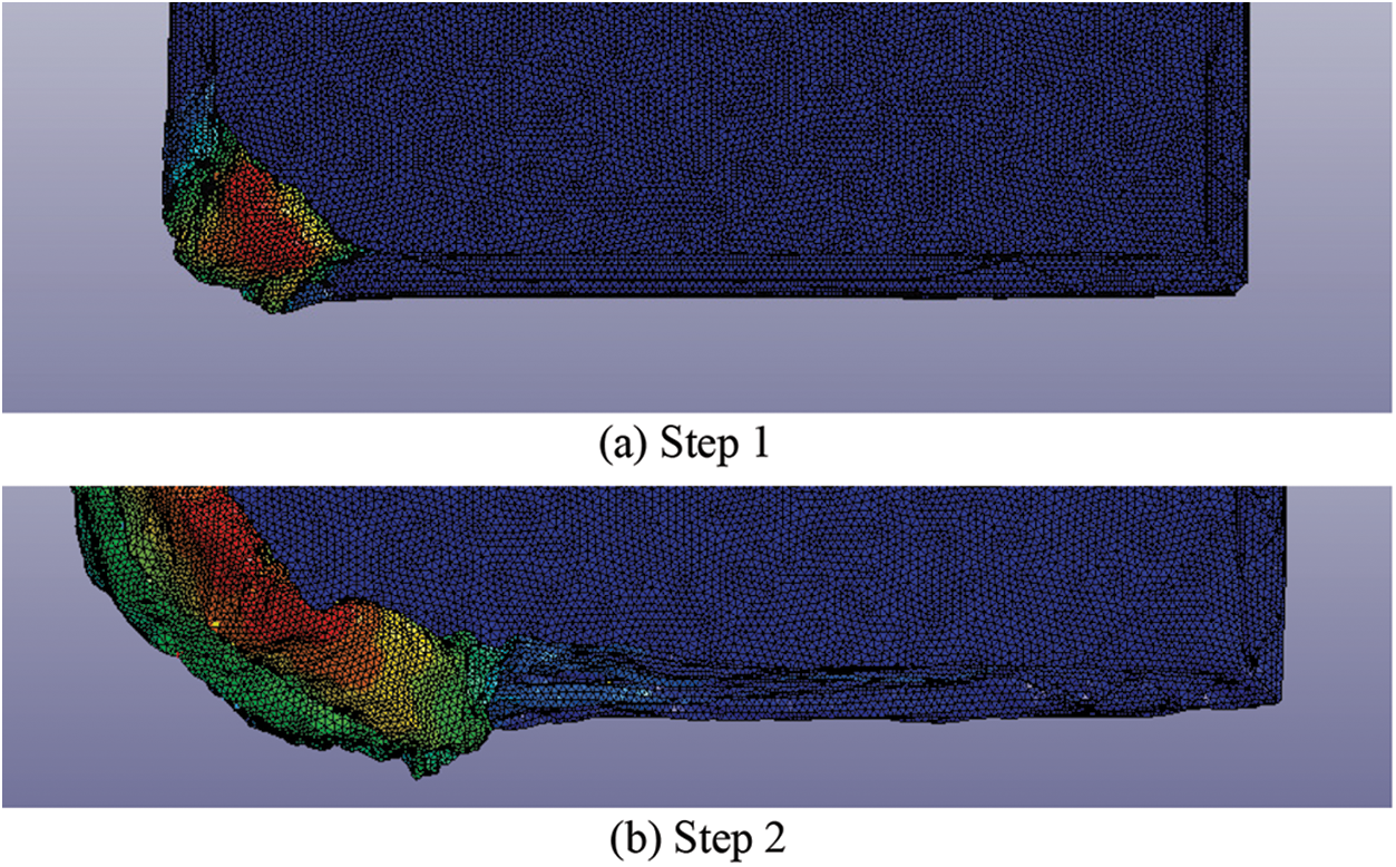
Figure 21: Displacement nephogram of inflatable deployment at side A of the “Z” type folding boarding platform
According to the comparison between the expansion of “Z” type folding and partial folding, it can be found that the way of airbag releasing from folding state is different when the gas flows. The unfolding process of partial folding airbags is flip from the inside out, the overturning degree is large and there is a certain range of swing after overturning. “Z” type folding is mainly moved outward from the fold, and there is no overturning process and swinging phenomenon.
The displacement images of the four selected units are analyzed, and the displacement images are shown in Fig. 22. Among them, the Z-direction motion displacement curve of S129453 unit is z1, that of S132455 unit is z2, that of S48413 unit is z3, and that of S43243 unit is z4.
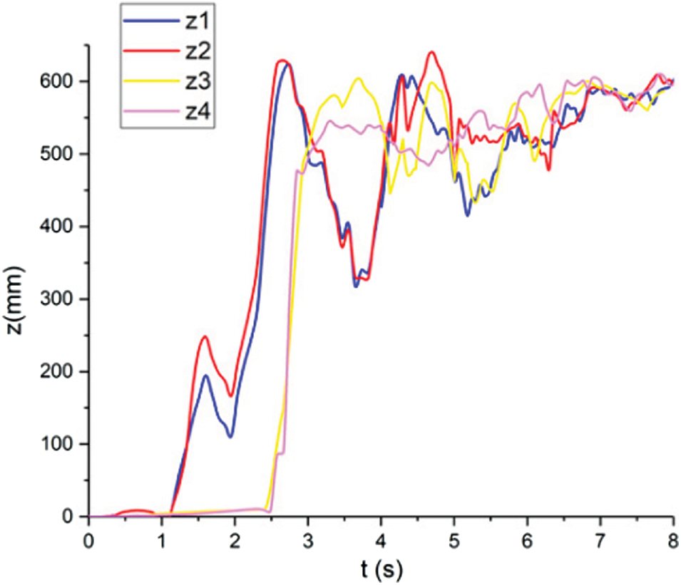
Figure 22: Displacement comparison of mesh units in different positions
From the Z-axis displacement image, at the beginning of inflation, the gas has not reached the four folded edges, and the A, C, E and G edges are still folded. At 1.1 s, S129453 unit on side A and S132455 unit on side G began to move, and rose to the extreme value at 2.7 s. This stage indicates that the gas flows to this place, which makes the mesh unit expand from the stacking state, and it rises to the maximum height for the first time, and then the displacement of the two units drops. At this time, the gas in the airbag cannot support the unit at this height, and the surface of the airbag is relatively loose, resulting in the mesh unit falling back. At 2.5 s, the displacement range of S43543 and S48413 on the C side and E side began to rise sharply, which indicated that a large amount of gas flowed there. Then the displacement of the four units gradually stabilized to 600 mm, and the boarding platform was fully expanded.
3.3 Inflatable Deployment of the Inner Spiral Folding Boarding Platform
Set the CPM method for the inner spiral folded boarding platforms. After solving through LS-DYNA, check the corresponding result d3plot result file in LS-PrePost. The displacement nephogram is shown in Fig. 23.
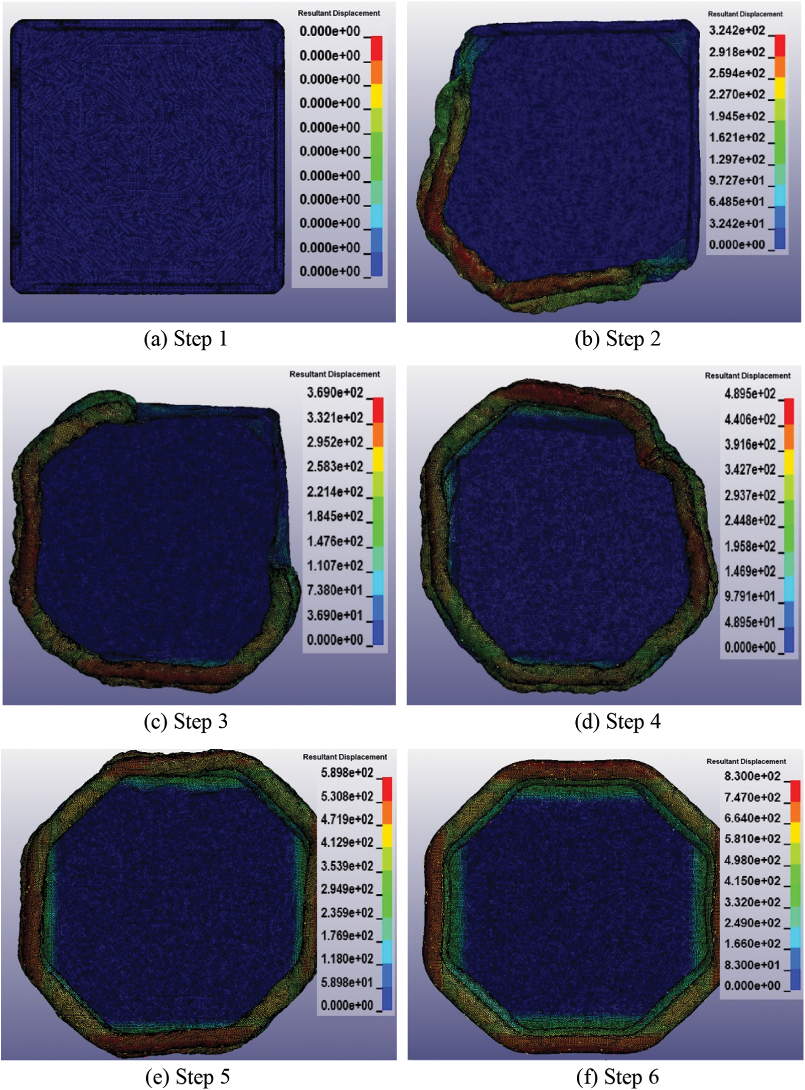
Figure 23: Displacement nephogram of the inner spiral folding boarding platform during inflation
The Fig. 23a shows that the inner spiral folded boarding platform is not inflated.
The Fig. 23b shows the gas flowing into the folded A and G sides. It can be observed that the airflow pushes the airbag surface out of the folded state during the filling process. At this time, the displacement of the mesh unit at the air inlet is large, which proves that most of the gas is accumulated here. The gas flows further from the air inlet to the left and right airway. From the air inlet position to the air flow forward position, it can be seen that the displacement change of the airbag surface is gradually attenuated, and the displacement change of the upper airbag is larger than that of the lower airbag. However, from the air flow forward position of the two airbags, it can be seen that the inflation of the upper and lower airbags with inner spiral folding has certain synchronization.
Fig. 23c shows that the gas flows to the C and E sides. At this time, the support of the air flow acts on the surface of the airbag in the same state as that of the A and G sides. At this stage, it can be seen that the displacement of mesh units at A and G sides is large, while the displacement of mesh units at the air inlet decreases. It is proved that at this time, a large amount of gas near the air inlet pushes to the left and right sides, flows to A and G sides, resulting in the increase of displacement of the surface of the airbags at these two places.
Fig. 23d shows that the air flow inside the annular airbag is through, at this time, the airbag surface of the four folded edges is unfolded from the inner spiral folding state by turning over. At this stage, there are a lot of folds on the surface of airbag, and it is relatively soft. At this stage, it can be seen that the displacement of the C and E sides of the airbag increases, and the displacement of the surface of the A and G sides decreases, indicating that more gas in these two places flows further outwards. For the first time, the left and right side of the gas meet at the D side, resulting in a slightly larger displacement of the airbag surface.
Fig. 23e shows that the airbag begins to enter the stage of fixed shape, in which the airbag has been inflated to a stable octagonal shape, and the surface of all the airbags has become a smooth surface through inflation expansion, into a state without depressions and folds.
Fig. 23f shows the boarding platform from the inner spiral folding to the fully inflated state.
Take part A as an example to analyze the initial stage of inflation process of the boarding platform in inner spiral folding mode, as shown in Fig. 24.
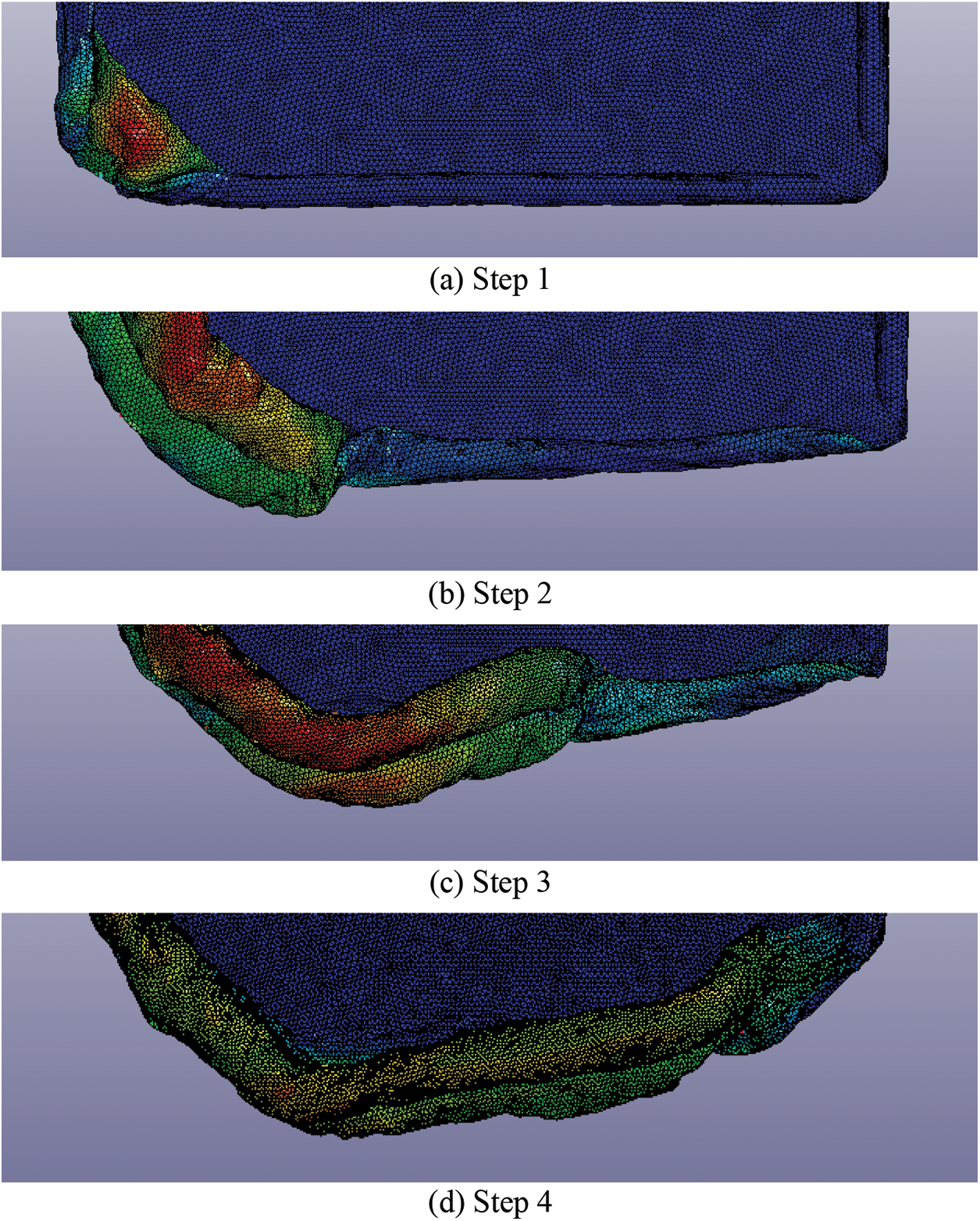
Figure 24: Displacement nephogram of inflatable deployment at side A of the inner spiral folding boarding platform
Compared with the previous two methods, the inflation of the inner spiral type is different in the initial stage: (1) There is no obvious fold line in the inner spiral model, the overturning range is small and the gas flow is smooth. (2) Under the action of gas, the surface of airbag has no inclination, little fluctuation and good stability.
In order to better analyze the unfolding characteristics of the boarding platform with inner spiral folding, the Z-axis displacement images of the four selected mesh units are compared and analyzed, as shown in Fig. 25. Among them, the Z-direction motion displacement curve of S129453 unit is z1, that of S132455 unit is z2, that of S48413 unit is z3, and that of S43243 unit is z4.
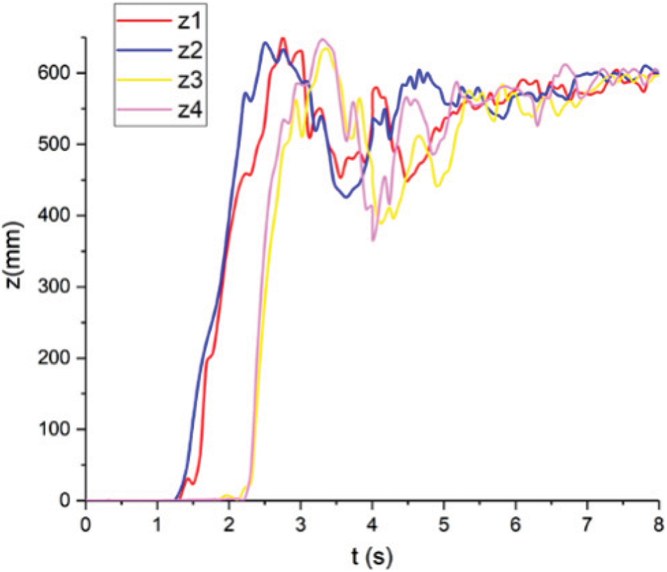
Figure 25: Displacement comparison of mesh units in different positions
From the Z-axis displacement curve, it can be seen that the S129453 unit on side A and S132455 unit on side G are synchronous during the initial deployment of the platform. Because there is a certain distance between the two units and the air inlet on side H, there is no displacement change at the time of 0 s inflation. At this time, the unit points are folded between the surfaces of multi-layer airbags. At 1.2 s, the filled gas starts to act on the two units, and the unit displacement starts to rise. When inflated to 2.4 s, the Z-direction displacement of S132455 unit rapidly rises to the extreme value. Inflate to 2.6 s, S129453 unit to peak. As the gas filled moves along the airway, the airbag surface is unfolded by overturning and breaking through the folding form. The two units reach the maximum Z-direction displacement for the first time in the process of overturning, and then the Z-direction displacement of the two units decreases because the gas in the airway is not enough to support the entire surface of the airbag. The gas continues to flow to the far end. At 2.3 s, the displacement of S43243 and S48413 on sides C and E began to change significantly. At this time, the gas flows to sides C and E for the first time. Then the two units move to the extreme position, which proves that the gas is acting at the unit position. At last, the displacement of each unit converges to 600 mm, and the platform is inflated.
In conclusion, it can be seen in the form of three different folding boarding platforms in the process of inflation have been through the same stages, respectively is A and G overturning from the folding state, C and E overturning from the folding state, the stage of fold disappearance after gas penetration, the shape fixing stage with smooth airbag surface, and the stage of completion of inflation when the axial displacement of the platform surface converges to 600 mm. In each stage, it can be found that the synchronization of the initial turning motion of the mesh units selected on edge A and edge G, edge C and edge E is relatively consistent, but the synchronization is poor after the gas is through. In each folding form, the specific form of the boarding platform deployment in each stage is different, and the starting and ending time of each stage is different, especially the time of inflatable deployment in different folding form is different.
4 Synchronization of the Inflation Process with Different Folding Modes
Through the above displacement image of Section 3, it can be found that when the gas flows from the left and right sides of the platform airbag, the displacement of the mesh units change synchronously. When the gas passes through the annular airbag, the displacement synchronization of the mesh units on the left and right sides of the platform is better at the initial stage of inflation, and it is the same to some extent at the later stage of the fold elimination stage and the shaping stage, and the displacement changes of the two sides are different at other stages of inflation. Therefore, this section will discuss the synchronization of the two stages in the inflation process of the boarding platform, i.e., the initial stage and the later stage, which are divided by the time when the gas passes through the annular airbag. In this section, we will study the issue of synchronization during the deployment of the upper and lower airbags. Select the upper surface mesh unit S129453 of the upper airbag on side A (Fig. 16), the upper surface mesh unit S14438 on the lower airbag (just overlaps with A). Select the upper surface mesh unit S43243 on the upper airbag on side C (Fig. 16) and the upper surface mesh unit S192593 on the lower airbag (just overlaps with C).
4.1 Synchronization of Inflation and Deployment of the Partial Folding Boarding Platform
The Z-direction displacement image of the four mesh units is shown in Fig. 26. Among them, the displacement curve of S129453 is z1, that of S14438 is z2, that of S43243 is z3, and that of S192593 is z4.
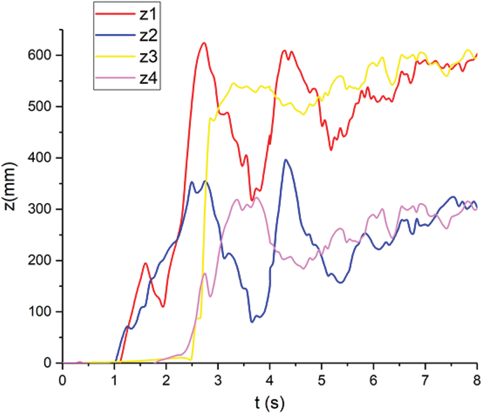
Figure 26: Displacement comparison of Mesh units on different surfaces of two airbags of the partial folded platform
In the initial stage of airbag inflation, the movement of the two units on side A is similar. When the displacement changes, the lower surface of the airbag moves 0.2 s ahead of the upper surface of the upper airbag. Due to the characteristics of partial folding mode, the lower airbag in the folding state wraps the upper airbag. At this time, S14438 is located above S129453. When the air flow passes, both the lower airbag pulls the upper airbag to turn outwards, and the upper airbag pushes the lower airbag to move outwards. Therefore, the lower airbag has priority over the upper one. In the process of initial displacement rising, the motion form of the two units is close. When the two units on side C are inflated initially, the S192593 of the lower airbag has some displacement in advance compared with the S43243 of the upper airbag, but the displacement range is not large. This process may be due to the expansion displacement of the mesh element already in contact with the gas. The displacement transfer on the airbag surface due to the material characteristics results in the movement of S192593, but at this time, the gas does not reach the unit or act on it. As a result, S192593 will produce a slight change in Z-direction displacement at the initial stage, but it is not inflated and unfolded, and it is still in the folding stage. But S43243 has some displacement changes in the folded multi-layer airbag fabric, but the range is not large. In the process of overturning, the displacement rise of the two elements is basically the same.
To sum up, the synchronization of two airbags in the initial stage of inflation is different to some extent, and the synchronization of movement changes in other stages is high. However, it can be found that the surface displacement of the folding boarding platform changes greatly in the period before the fold elimination stage, which results in the instability of the boarding platform inflation and deployment.
4.2 Synchronization of Inflation and Deployment of the “Z” Type Folding Boarding Platform
The Z-direction displacement image of the four mesh units is shown in Fig. 27. Among them, the displacement curve of S129453 is z1, that of S14438 is z2, that of S43243 is z3, and that of S192593 is z4.
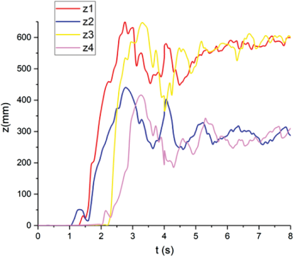
Figure 27: Displacement comparison of Mesh units on different surfaces of two airbags of the “Z” type folded platform
In the “Z” type folding mode, the height of the edge involved in the folding is high, and the number of layers on the surface of the airbag wrapped around the selected unit is large. In the initial stage of inflation, the mesh unit selected on the side A has no obvious displacement change. It can be seen from the corresponding displacement nephogram above that when the gas does not flow to the folding edge, the top layer airbag surface in the “Z” folding is in the state of the upper airbag pressing the lower airbag, and there is slight displacement change on the top layer airbag surface. The selected two units are located in the fourth layer of “Z” type folding, and the airbag status of this layer is that the lower airbag presses the upper airbag. Therefore, in the process of unfolding, S14438 of the lower airbag moves 0.3 s earlier than S129453 of the upper airbag. After that, the movement displacement of the two units is similar, but slightly different in the shape fixing stage. The two units on side C are in the fourth layer in the folding, and the S192593 of the lower airbag is above the s43243 of the upper airbag. In the initial deployment, the z-direction motion of the lower airbag is preferred. The movement changes of the two units are slightly different in the initial development, and have a high similarity in the later stage.
To sum up, due to the large layers number of “Z” type folding, the synchronization of the two airbags in the initial stage of inflation is poor, and the lower airbags affect the upper airbags’ deployment. In the Folding elimination stage and the later inflation stage, the synchronization is more consistent, and the fluctuation in the Fig. 27 is more stable than that in the partial folding.
4.3 Synchronization of Inflation and Deployment of the Inner Spiral Folding Boarding Platform
Capture the movement of four units during the inflation of the inner spiral folding boarding platform, and draw the Z-direction displacement image, as shown in Fig. 28.
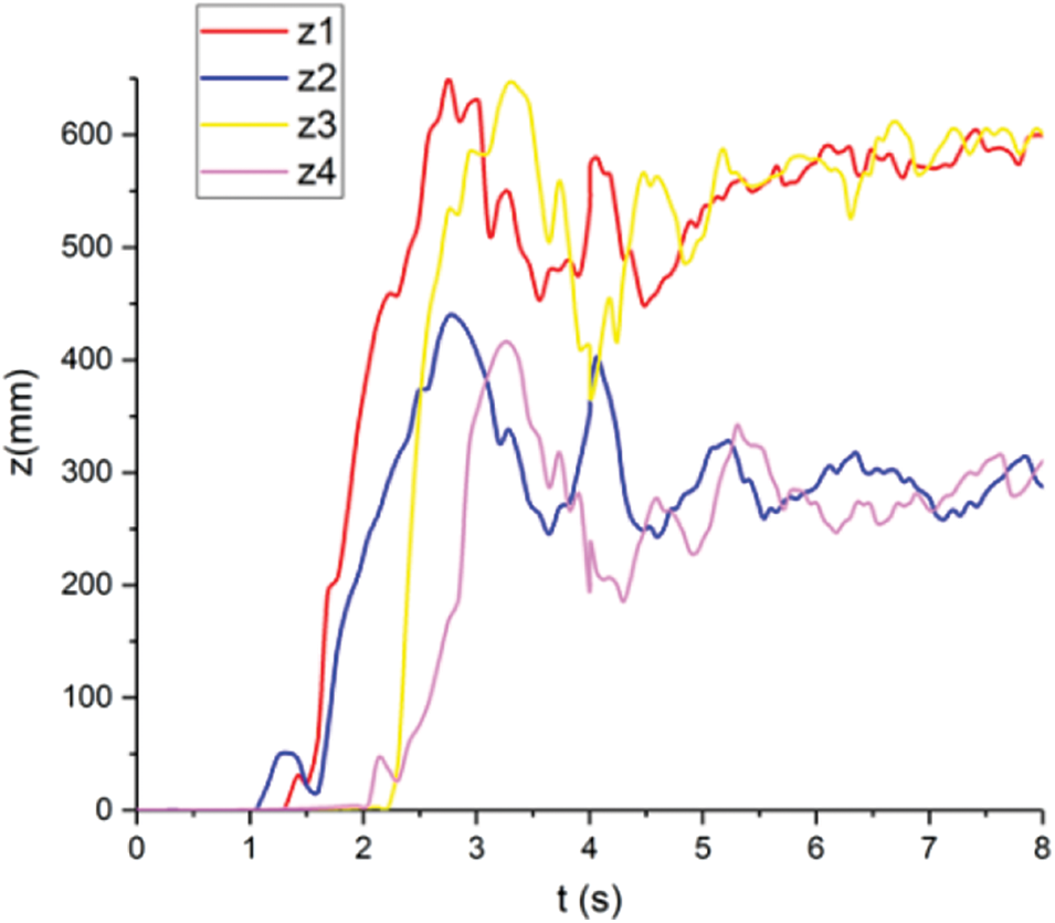
Figure 28: Displacement comparison of Mesh units on different surfaces of two airbags of the inner spiral folded platform
Compared with the former two folding methods, the difference of the inner spiral folding is that the surface of the upper and lower airbags of the platform basically fits, there is no obvious corner, after folding, there is only the number of turns, there is no the number of layers. The selected upper airbag unit is closer to the inner circle than the lower airbag unit, and each circle can be regarded as the lower airbag wrapping the upper airbag. Therefore, when the gas flows, S14438 near the outer ring on side A moves preferentially than S129453 near the inner ring, and the time difference is about 0.3 s. However, the displacement of the upper airbag is faster than that of the lower airbag, and the former two folding modes do not show this phenomenon. The initial movement on side C is also S101937 of the lower airbag slightly prior to S122131 of the upper airbag, and then the movement of the upper airbag changes faster than that of the lower airbag. It can be seen from the Fig. 28 that in each stage of the inflation deployment process, the up and down airbags of the inner spiral folding boarding platform have good synchronous motion changes, and the fluctuation amplitude is less than the other two, so the platform deployment stability is better.
To sum up, the synchronization of the two airbags in each stage of inflation is different in three different folding modes. The synchronization of each stage of the inner roll folding is high. In the displacement image, the Z-direction displacement of the lower airbag is higher than that of the upper airbag for a short time. This phenomenon is not due to the movement of the lower airbag above the upper airbag, but to the violent overturning of the airbag at the beginning of unfolding, so that the two mesh units are not in a vertical direction. In the displacement image, it can be seen that the movement of the mesh unit of the lower airbag is more complicated than that of the upper airbag, because the upper surface of the upper airbag is mainly affected by the inflation of the upper airbag, and the lower airbag has less impact, while the upper surface of the lower airbag is affected by the inflation of two airbags at the same time.
Based on the displacement analysis of the mesh units in different positions, the following conclusions can be drawn: (1) The synchronization of the left and right sides of the platform is better in the initial stage, and there are some differences in the synchronization of the stages after the gas through the platform. (2) Due to the different stacking states of the upper and lower airbags in different folding modes, the synchronization is different in the initial stage, and the movement changes are more consistent in the rest stages, among which the synchronization of the inner spiral folding is better than that of the partial folding and the “Z” type folding in each stage. (3) When the two airbags of the boarding platform are inflated, the inner spiral folding platform has a small fluctuation range, a stable turnover process and the best stability in the deployment process.
During the deployment of the marine evacuation system, the inflation process of the boarding platform is easy to be blocked and unable to be inflated into a stable circular shape. The influence of the folding mode on the inflation and deployment of the boarding platform is discussed. Based on PRIMER software, three kinds of models, which are partial folding, “Z” type folding and inner spiral folding, are established, and the CPM algorithm is preprocessed in LS-PrePost. Through the solution of LS-DYNA, the feasibility of the complete deployment of the boarding platform under three folding modes is verified. Through the comparative study of the state characteristics of different folding modes in the deployment process, the following conclusions are obtained:
(1) In the process of the platform inflation, the way airbags are released from the folded state is different when the air flows. Partial folding type is from the inside to the outside, the degree of turning is large and there is a certain swing process after turning out. The “Z” type folding mainly moves from the folding place directly upward to outward, without turning process and swinging phenomenon. During the unfolding process of the inner spiral platform, the overturning amplitude is small, the fluctuation amplitude is small, and the stability is good. In conclusion, the folding efficiency of partial folding type is the highest, the folding expansion speed of the “Z” type is the fastest, and the platform rescue effect of the inner spiral is the best.
(2) Based on the analysis of the Z-axis displacement images of the selected mesh units, it can be found that 3 kinds of different folded boarding platforms have gone through the same stages in the deployment process, namely, the flipped deployment of side A and side G, and after 1.4∼1.5 s, the flipped deployment of side C and side E, the folding extinction stage after the gas through and the stable shaping stage. In each stage, it can be found that the displacement characteristics of the initial turning motion of the mesh elements selected on edge A and edge G, edge C and edge E are consistent, but the synchronization of the displacement changes is 0.2∼0.3 s after gas through.
(3) In terms of the synchronization of the deployment process of the platform with three different folding modes, it is found that the synchronization of the left and right sides of the platform is better in the initial stage, and the synchronization of the upper and lower airbags is better in the later stage (about 2.6 s). In the stage of inflatable deployment, the inner spiral folding platform has a small fluctuation range, a stable turnover process and the best stability in the deployment process.
Funding Statement: This paper is financially supported by High-Tech Ship Scientific Research Project in 2018 (Research on Key Technologies of Polar Small Cruise Ship Design and Construction, Ministry of Industry and Information Technology Packing Letter [2018] No. 473 and Emergency Evacuation Chute System Development, Ministry of Industry and Information Technology Packing Letter [2017] No. 614).
Conflicts of Interest: The authors declare that they have no known competing financial interests or personal relationships that could have appeared to influence the work reported in this paper.
References
1. Che, X., Yang, Y. (2013). Safety reserve of fixed offshore platform structures: A review. The Ocean Engineering, 32(1), 117–124. [Google Scholar]
2. Ping, P., Wang, K., Kong, D. (2018). Analysis of emergency evacuation in an offshore platform using evacuation simulation modeling. Physica A: Statistical Mechanics and its Applications, 505, 601–612. DOI 10.1016/j.physa.2018.03.081. [Google Scholar] [CrossRef]
3. Raman-Nair, W., Chin, S. N., Simoes-Re, A. (2007). Numerical model of a marine chute evacuation system. Ocean Engineering, 34(5–6), 739–746. DOI 10.1016/j.oceaneng.2006.05.002. [Google Scholar] [CrossRef]
4. Viking life-saving equipment A/S (2022). VIKING SES−2A 2006. https://myviking.viking-life.com/en/Evacuation-Systems/Offshore-Evacuation-Systems/Chute-systems?p/SES-2A+2006. [Google Scholar]
5. Kong, F., Xu, H., Wang, Z., Ge, H., Wang, B. (2019). Dynamic response analysis of marine evacuation chute system. IEEE International Conference on Mechatronics and Automation (ICMA), pp. 2088–2093. Tianjin, China. DOI 10.1109/ICMA.2019.8816623. [Google Scholar] [CrossRef]
6. Abramowicz-Gerigk, T., Burciu, Z. (2012). Analysis of safety requirements for large offshore units evacuation systems. LSA Safety Function. Archives of Transport, 24(4), 429–440. DOI 10.2478/v10174-012-0026-0. [Google Scholar] [CrossRef]
7. Viking life-saving equipment A/S (2022). Chute systems. https://www.viking-life.com/en/evacuation-systems-/offshore-evacuation-systems/chute-systems. [Google Scholar]
8. Kong, F., Liu, H., Wang, B., Ding, H., Jiang, Z. et al. (2020). Wind-load response and evacuation efficiency analysis of marine evacuation inflatable slide. Applied Sciences, 10(1), 21. DOI 10.3390/app10010021. [Google Scholar] [CrossRef]
9. Cadogan, D., Sandy, C., Grahne, M. (2002). Development and evaluation of the Mars pathfinder inflatable airbag landing system. Acta Astronautica, 50(10), 633–640. DOI 10.1016/S0094-5765(01)00215-6. [Google Scholar] [CrossRef]
10. Petit, P., Trosseille, X., Baudrit, P., Gopal, M. (2003). Finite element simulation study of a frontal driver airbag deployment for out-of-position situations. Stapp Car Crash Journal, 47, 211–241. DOI 10.4271/2003-22-0011. [Google Scholar] [CrossRef]
11. Zhang, J., Ma, C., Bai, Y., Huang, S. (2005). Airbag mapped mesh auto-flattening method. Tsinghua Science & Technology, 10(3), 387–390. DOI 10.1016/S1007-0214(05)70086-9. [Google Scholar] [CrossRef]
12. Ritmeijer, P., Happee, R., Bosch-Rekveldt, M., van der Made, R. (2005). Validation of gasflow airbag simulation methods. SAE 2005 World Congress & Exhibition, SAE Technical Papers 2005–01–1230. Detroit. DOI 10.4271/2005-01-1230. [Google Scholar] [CrossRef]
13. Blümcke, E., Luijkx, R., Ezquerra Larrode, F. (2008). Numerical and experimental investigations of the deployment behaviour of a knee airbag featuring real gas flow phenomena. FISITA World Automotive Congress 2008, Congress Proceedings-Testing and Simulation, pp. 608–614. Munich. [Google Scholar]
14. Zhang, J., Li, D., Bi, Y., Yang, D., Qiu, F. (2009). Optimization of vehicle side curtain airbag module based on computer aided engineering. Chinese Journal of Mechanical Engineering, 22(4), 521–527. DOI 10.3901/CJME.2009.04.521. [Google Scholar] [CrossRef]
15. Wei, J. Z., Ma, R. Q., Tan, H. F., Du, X. W. (2012). Simulation for gas-membrane interaction of folded membrane tubes during inflation. Advanced Materials Research, 594–597, 2627–2631. DOI 10.4028/www.scientific.net/AMR.594-597.2627. [Google Scholar] [CrossRef]
16. Radek, G., Vincent, C., Mohsen, S. (2018). Comparative finite element and experimental analysis of a quasi-static inflation of a thin deployable membrane space structure. Finite Elements in Analysis and Design, 138, 48–65. DOI 10.1016/j.finel.2017.09.004. [Google Scholar] [CrossRef]
17. Yu, L., Zhan, Y. N., Shi, Y. F., Zhao, X. S., Liu, X. (2017). Numerical simulation for damping-controlled deployment of z-folded inflatable tube. Transactions of Nanjing University of Aeronautics and Astronautics, 34(4), 420–425. [Google Scholar]
18. Zhao, X. S., Jia, H., Sun, Z., Yu, L. (2019). Modeling inflatable fabric with undevelopable surfaces by motion folding method. Journal of Engineered Fibers and Fabrics, 14, 1–14. DOI 10.1177/1558925019886408. [Google Scholar] [CrossRef]
19. Salama, M., Kuo, C., Lou, M. (2000). Simulation of deployment dynamics of inflatable structures. Renewable Energy, 38(12), 2277–2283. DOI 10.2514/2.896. [Google Scholar] [CrossRef]
20. Wan, X., Yang, J., Shen, B. (2005). Influence of airbag folding pattern on deployment loads using virtual testing technique. Chinese Journal of Mechanical Engineering, 41(12), 162–166. DOI 10.3901/JME.2005.12.162. [Google Scholar] [CrossRef]
21. Young, K., Kurt, F., Eyad, N., Hyeong, C. (2012). Single stage driver airbag module development for OOP. SAE 2012 World Congress and Exhibition, SAE Technical Paper 2012–01–0083. Detroit. DOI 10.4271/2012-01-0083. [Google Scholar] [CrossRef]
Cite This Article
 Copyright © 2023 The Author(s). Published by Tech Science Press.
This work is licensed under a Creative Commons Attribution 4.0 International License , which permits unrestricted use, distribution, and reproduction in any medium, provided the original work is properly cited.
 Downloads
 Citation Tools