
 Submit a Paper
 Propose a Special lssue
 Open Access
ARTICLE
Free Vibration Analysis of Rectangular Plate with Cutouts under Elastic Boundary Conditions in Independent Coordinate Coupling Method
1 College of Mechanical and Electrical Engineering, Harbin Engineering University, Harbin, 150001, China
2 SAE Concepts, East Brunswick, NJ, 08816, USA
3 No.709 & Institute, China Shipbuilding Industry Corporation (CSIC), Wuhan, 430205, China
4 No.710 & Institute, China Shipbuilding Industry Corporation (CSIC), Yichang, 443003, China
* Corresponding Author: Wenhao Huang. Email:
(This article belongs to the Special Issue: Computer Modeling in Ocean Engineering Structure and Mechanical Equipment)
Computer Modeling in Engineering & Sciences 2023, 134(3), 2093-2121. https://doi.org/10.32604/cmes.2022.021340
Received 09 January 2022; Accepted 09 May 2022; Issue published 20 September 2022
 View Full Text
 Download PDF
Abstract
Based on Kirchhoff plate theory and the Rayleigh-Ritz method, the model for free vibration of rectangular plate with rectangular cutouts under arbitrary elastic boundary conditions is established by using the improved Fourier series in combination with the independent coordinate coupling method (ICCM). The effect of the cutout is taken into account by subtracting the energies of the cutouts from the total energies of the whole plate. The vibration displacement function of the hole domain is based on the coordinate system of the hole domain in this method. From the continuity condition of the vibration displacement function at the cutout, the transition matrix between the two coordinate systems is constructed, and the mass and stiffness matrices are completely obtained. As a result, the calculation is simplified and the computational efficiency of the solution is improved. In this paper, numerical examples and modal experiments are presented to validate the effectiveness of the modeling methods, and parameters related to influencing factors of the rectangular plate are analyzed to study the vibration characteristics.Keywords
Rectangular plate structures are widely applied in a variety of engineering fields such as aerospace, marine, and automobile manufacturing. When taking into consideration the necessity of including equipment channels, the reduction of weight, and actual installation, it is often necessary to cut holes on the plate structure. The presence of the holes changes the quality and stiffness of the plate and influences the vibration characteristics and the stability of the plate structure [1]. Generally, these plate structures are subjected to all kinds of complex environmental forces; from the continuous action of various loads inside or outside of the plate to the potential for resonance, environmental influence will generate noise and could even lead to serious structural damage. Therefore, some researchers have focused on the vibration characteristics of the rectangular plate with holes for anti-noise applications, vibration reduction and the engineering of key structural designs [2]. Various methods were developed and can be organized into two categories: discrete methods and semi-analytical methods.
In the analysis of rectangular plate with cutouts, discrete methods, such as the finite difference technique [3,4], the boundary element method [5,6], the differential quadrature method (DQ) [7], the mesh-free radial point interpolation method [8], the finite element method [9–11] and the discrete singular convolution method (DSC) [12], have commonly been applied. These methods generally scatter the analyzed structure. As the frequency of this analysis increases, refinement of the process is required; the absence of which can lead to a rapid increase in the amount of calculation. In addition, valuable opportunities for understanding the nature of the problem are often lost during the solution process. This type of analysis lacks the flexibility for further research on sensitivity analysis, parameter optimization and active control mechanism of structural vibration.
In contrast with discrete methods, the semi-analytical methods for rectangular plate with cutouts pay attention to the relationship of rectangular plates with cutouts. Currently, research has mainly focused on three aspects: the region segmentation, the equivalent substitution, and the separation of cutouts and plate domains. Then, to examine the vibration characteristics of the rectangular plate with cutouts, semi-analytical methods generally used are the Rayleigh-Ritz methods (RRM) [2,13,14], the multi-term extended Kantorovich method (MEKM) [15], the extension of Hencky bar-net method [16], Chebyshev-Lagrangian method [17], the Green function method [18], the superposition method, the assumed mode method [19,20], the improved Fourier series method [21,22], the Dynamic Stiffness Method (DSM) [23], and the Spectro-Geometric Method (SGM) [24].
In the analysis of plates using semi-analytic methods, the cutouts are realized by proper representation of the plate as composed of several subdomains. Lee and Lim carried out the free vibration frequencies of square plates with square cutouts subjected to in-plane forces by sub-dividing the plate into sub-domains [14]. Liew et al. [25,26] applied this concept to the analysis of a rectangular plate with central cutouts using the domains decomposition method. Shufrin et al. [27] used the multi-term extended Kantorovich method to the in-plane vibrations of rectangular plates with rectangular cutouts by considering several proper sub-domains of plate. Shufrin et al. [15] then applied this method to the free vibration analysis of rectangular plates with rectangular cutouts and variable thickness. Wang et al. [28] analyzed the free vibration characteristics of a rectangular plate with a rectangular opening based on Fourier series method. Yuan et al. [29] applied the modified vibrational method to study the vibration characteristics of structures of plates with a hole and reinforcement plates in ships; the displacement and rotation components of each plate segment are expanded by Chebyshev orthogonal polynomials of the first kind.
On the vibration analysis of rectangular plates with cutouts, some researchers examined the problem from an alternative perspective by using the equivalent substitution method. The rectangular plate with cutouts is considered the equivalent rectangular plate with non-uniform thickness.
Based on this idea, Huang et al. [18] investigated the free vibration of rectangular plates with variously-shaped holes by applying the discrete Green function method. Wang et al. [24] applied the Spectro-Geometric method to study an elastically restrained plate with arbitrary holes. The hole is considered to be a virtual plate in which the mass density and the Young’s modulus zero. Chen et al. [17] discussed rectangular plate with cutout under general boundary constraints by the Chebyshev-Lagrangian method. They used a method of setting the structure and material parameters associated with the cutouts domain to zero. Jafari et al. [30] mapped onto the finite area with a rectangular hole to finite area with unit circle and then calculated the vibration characteristics.
Additional research focused on the separation of cutouts and plate domains by removing the effect of the hole domain from the total energies of the whole plate. Cho et al. [19,20] applied the assumed mode method to analyze vibration characteristics of rectangular plate structures with holes and attachments. In these investigations, holes, plates, stiffeners and structures were considered as independent energy elements upon which the Lagrange’s equation and modal superposition method were applied to obtain the vibration response of rectangular plate structures. Huang [31] developed the receptance approach for in-plane vibration of a rectangular plate with a hole. This method considered the hole and plate as sub-structures and performed sub-structural addition and deduction simultaneously. Wagner et al. [32] applied the energy modification method to study the vibration characteristics of rectangular plate with a rectangular or circular hole. They also successfully used this method in the structural optimization of a plate with multiple holes. Ali et al. [33] first proposed the Rayleigh method to analyze the vibration problem of a plate with a hole, and solved for the vibration frequency of the same plate with rectangular holes under simply-supported boundary conditions. Avalos et al. [34–36] used RRM obtained the frequency parameters of the anisotropic plate under free boundary conditions and explore the effect of structural factors, such as aspect ratio, open rate (ratio of aperture to plate length), and hole position, on vibration frequency.
However, in the process of solving the vibration of a rectangular plate with a complex hole shape and a plurality of rectangular holes, complicated numerical calculations are derived when integrating the vibration displacement function of holes domain in the integral operation, thereby greatly reducing the computational efficiency of the solution and the applicable range.
To solve this problem, Kwak et al. [37] proposed an independent coordinate coupling method based on RRM to the relationship holes domain and plate domain. In this method, the vibration displacement function and the energy equation of the plate and the hole are respectively established on the basis of their own independent coordinate systems. The connection between the hole and the plate is established through the coupling relationship of the respective vibration displacement function in the holes domain and the conversion matrix is constructed, thereby seeking the overall quality and stiffness matrix. This method exhibits good convergence while satisfying the exact requirements of the solution, and greatly simplifies the calculation, especially in the vibration solution of plate with multiple holes. This method for computational efficiency has been developed by many researchers. Huang et al. [38] adopted the Rayleigh–Ritz method and the Lagrange’s equation to the free vibration of an especially orthotropic laminate with central rectangular cutout. Mochida et al. [23] used the Dynamic Stiffness method and Rayleigh-Ritz method for the theoretical basis for combining positive and negative structures. Merneedi et al. [39] analyzed the free vibration of a rectangular plate with different sizes of multiple circular and rectangular under simply-supported boundary condition. Guo et al. [40] investigated the free vibration of a functionally graded carbon nanotube-reinforced plate with a central hole by the independent coordinates-based Rayleigh–Ritz method.
The influence of various factors on the vibration characteristics of a rectangular plate with cutouts has been under investigation in the literature. Many researchers discussed the position of cutouts [4,15,17,21] as a central hole, corner hole and edge hole, and analyzed the applicability and accuracy of their methods. The opening ratio and number are directly related to the mass and stiffness of plate structure, which in turn naturally affects the vibration characteristics and stability of structure. Therefore, research on analytical methods has been conducted with a particular focus on these factors [26,36,41].
On boundary conditions, early researchers mainly discussed the classical boundary conditions, such as free edges, simply-supported and clamped [42]. Recently, research has focused on extending from the original classical boundary conditions to general boundary conditions. In doing so, the plate mechanics are influenced instead by setting groups of boundary springs and assigning corresponding stiffness constants to springs. Chen et al. [17] handled rectangular plates with inner cutouts or corner cutouts using the Chebyshev–Lagrangian method. Cho et al. [19,20] and Nie et al. [43] analyzed rectangular plates with multiple openings by the assumed mode method. Wang et al. [28], Liu et al. [22] and Shi et al. [21] discussed rectangular plate with inner cutouts or edge cutouts by the improved Fourier series method. Wang et al. [24] adopted the Spector-Geometric method to rectangular plate with triangular and rectangular holes.
From the above literature review on vibration of coupled plates, we can see two important points. Some of the literature only consider the vibration characteristics of rectangular plate with holes under classical boundary conditions. Others consider arbitrary boundary conditions, but they were still based on traditional coordinate system methods when dealing with the relationship between plates and holes. Our research aims to further generalize and improve the analysis of plates with holes.
In this paper, we study the vibrations of rectangular plate with cutouts using classical Kirchhoff plate theory. We develop the governing equations, and apply the Fourier series method and finite element software to solve for the vibration displacements. But due to the nature of the rectangular plate problem, discontinuities can occur when the Fourier series method is applied directly. To resolve this issue, the Fourier series method must be amended to suit this problem by constructing a solution as a linear combination of a standard two-dimensional Fourier cosine series and auxiliary series functions. It has been shown that this solution method works very well for a variety of edge supports. Additionally, for the relationship between plate and aperture, Rayleigh Ritz method and independent coordinate coupling method (ICCM) are used to analyze the vibration of rectangular plates with cutouts under arbitrary boundary conditions. The accuracy and convergence characteristics of this method are demonstrated through numerical examples and experiments. In Section 2, the preliminary background concepts and the analysis of the plate structure using the improved Fourier series method are provided. In Section 3, numerical simulations and results are presented. In Section 4, modal experiments of rectangular plate with cutouts are conducted, and concluding remarks are provided in Section 5.
2 Modeling of Rectangular Plate with Cutout
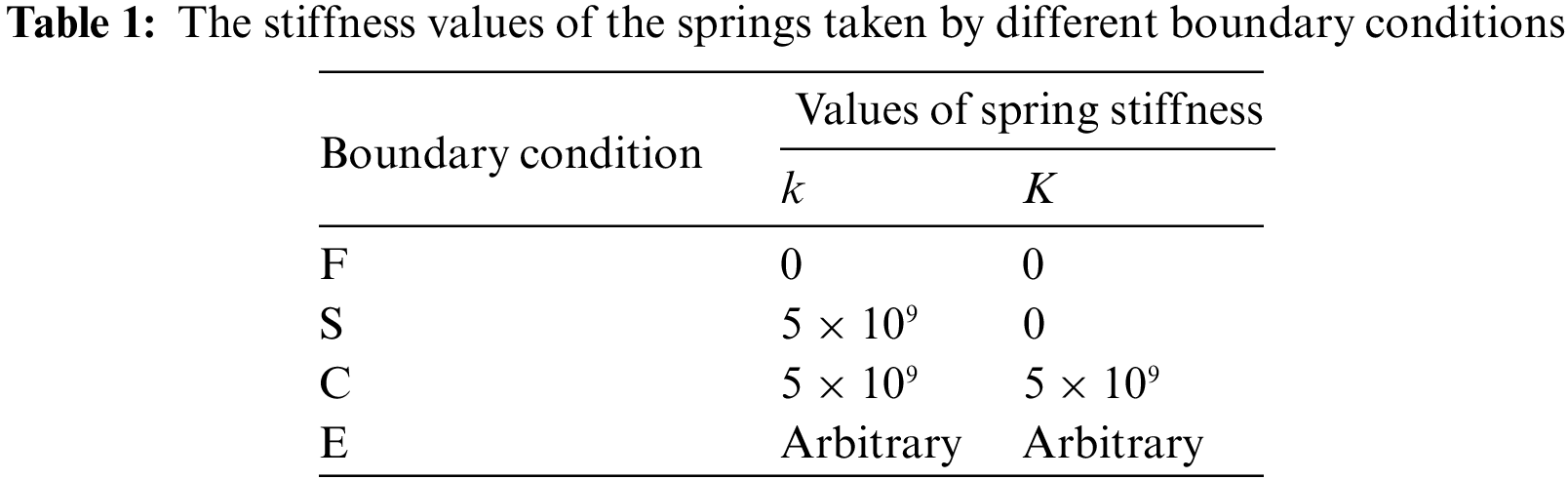
In this paper, the free vibration of a rectangular plate with a rectangular cutout under arbitrary elastic boundary conditions is studied. The model of a rectangular plate with a cutout is shown in Fig. 1. Around the outer boundary are a uniformly distributed displacement-constrained spring and the torsion-constrained spring, which simulate any elastic boundary condition by setting an appropriate stiffness value. The rectangular cutout has no spring constraint and is a free boundary condition. Using Lagrange-Kirchhoff theory, the governing equations of the free vibration of the plate is:

Figure 1: The model of rectangular plate with cutout
where D is the bending stiffness,
The vibration displacement function of a rectangular plate is represented by two variables separated along the x-axis and the y-axis. The plate displacement w is expressed the improved Fourier series as shown:
where
where
The boundary conditions for the flexible rectangular plate are given in the global coordinate system as follows:
on
on
on
on
where
The boundary conditions for the cutout are given as follows:
on
on
on
on
where,
The Rayleigh-Ritz energy method is an overall good and simple solution to the rectangular plate. In this paper, the improved Fourier series method and the Rayleigh-Ritz energy method is combined to determine the free vibration solution of rectangular plate with a cutout. The energy of the rectangular plate with a cutout is equal to the energy of rectangular plate domain minus the energy of the rectangular hole domain. Taking the model shown in Fig. 1 as an example, the Lagrangian function of the rectangular plate with a cutout can be expressed as:
where
The strain energy, potential energy and kinetic energy for the plate can be expressed as:
The strain energy, potential and kinetic energy for the cutout can be expressed as:
Thus, in terms of the plate and cutout energy terms, Eq. (6) can be also expressed as:
In order to satisfy the simplification of the integral orthogonality for the vibration displacement function of the rectangular hole domain under the ICCM, the vibration displacement function of the rectangular hole under the free boundary condition adopts the uniform beam function consistent with [37]. We nondimensionalize the coordinates of the rectangular cutout variables
where,
where the parameters
The form for
As shown in Fig. 1, dimensionless hole domain coordinate and plate domain coordinate variables satisfy the following relationship:
Substitution of Eqs. (2) and (10) into Eq. (13) produces the following:
Multiplying
Due to the integral orthogonality of the vibration displacement function of the rectangular hole, Eq. (16) can be stated as follows:
or more simply in matrix form as:
where,
where:
Eq. (20) can be expressed non-dimensionally as:
where
where
and the expression for a rectangular plate with a hole is as follows:
where
where M, N is the truncation number of displacement that determines the computational precision of natural frequency.
As Fig. 1 shows a single rectangular hole, the total energy can be computed by subtracting the energy belonging to the hole from the energy of the entire rectangular plate. While it is a more complicated solution process, the improved Fourier series and Rayleigh-Ritz method under the globe coordinate system (IFRM) is more accurate than traditional Rayleigh-Ritz method. However, as for the rectangular plate with multiple holes, the IFRM is not easy due to the complex integral limit, the longer calculating time, and the lower solution efficiency. Thus, the independent coordinate coupling method can be combined with IFRM to solve to the free vibration problem for the rectangular plate with multiple holes, as shown on Fig. 2, where

Figure 2: The model of rectangular plate with multiple cutouts
where,
Here, Eqs. (26a) and (26b) can be substituted into Eq. (24) for the free vibration equation of rectangular plate with multiple cutouts, and then the corresponding free vibration frequency can be obtained.
To verify the applicability and accuracy of the models developed in Section 2, several examples involving various boundary conditions were discussed for solving the free vibration of the rectangular plate with cutouts. In the following numerical analysis, the structural and material parameters of the rectangular plate with cutouts are: the thickness of plate
3.1 The Convergence for Verification of the Model
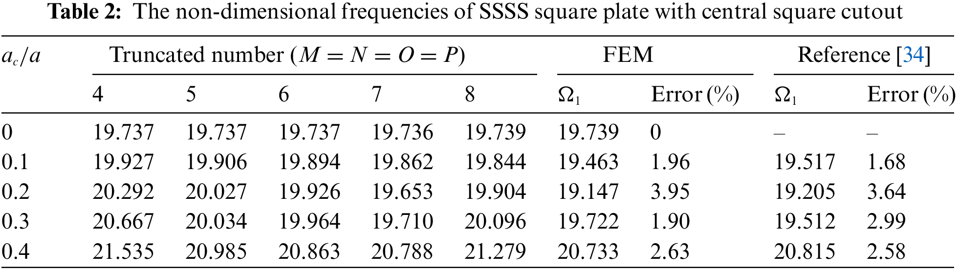
In the present theoretical model, the vibration displacement function is expressed as an improved Fourier series expansion, which is a key factor of the solution precision. In theory, the accuracy of solution increases with the increase of truncated number M, N and converges to the exact solution. However, considering the limited capacity, numerical accuracy and speed of computers, the series expansion must be truncated to M and N to obtain the results [34] with acceptable accuracy. Therefore, we need to examine the convergence and accuracy of the proposed method to establish the number of series expansion terms needed to obtain accurate results.
Table 2 shows the non-dimensional frequencies
To further verify the effectiveness of the method, the natural frequencies and mode shapes of a rectangular plate with a general eccentric cutout under CCCC boundary condition are calculated; the results are shown in Table 4. The size and position parameters of the rectangular plate with cutout are:
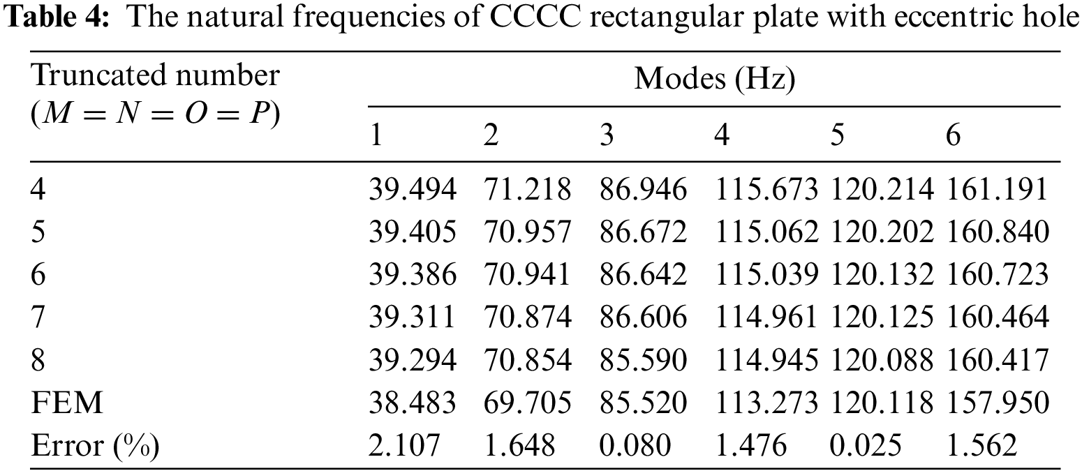
The resulting natural frequencies calculated by this present method and the finite element method are shown in Table 4, Figs. 3 and 4, from which can be seen that the maximum error of natural frequencies does not exceed 2.107 % by the two methods. As Figs. 3 and 4 show, when we compare the mode shapes computed by each method, the distribution patterns of the mode shapes and pitch circles of the rectangular plate with eccentric cutout obtained by the two methods are consistent. Overall, the data shows that the present method is more accurate for rectangular plates with an eccentric cutout.

Figure 3: The mode shapes of rectangular plate with eccentric cutouts under CCCC boundary condition by FEM

Figure 4: The mode shapes of rectangular plate with eccentric cutouts under CCCC boundary condition by the present method
3.2 Analysis under Variable Boundary Conditions
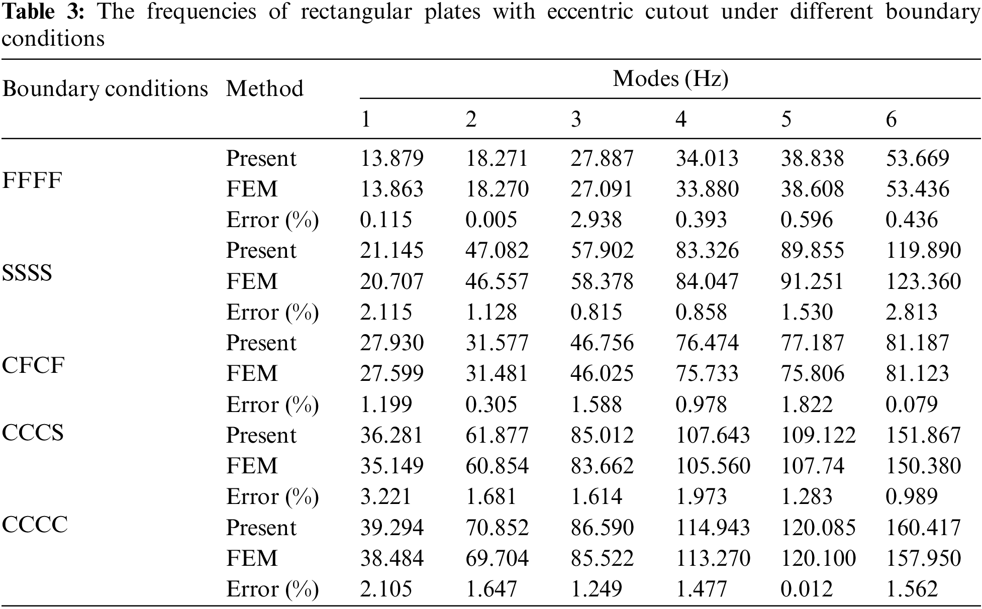
In order to verify the accuracy of the present method under classical boundary conditions, Table 3 provides the results of rectangular plate with an eccentric cutout. Different boundary conditions can be obtained directly by changing the stiffness magnitudes of the springs, and all classical homogeneous boundary conditions–clamped and free boundaries–can be easily derived by setting each of spring constants to be infinite or zero, respectively. The simply-supported boundary can be obtained by setting the displacement spring stiffness of each edge to be
In addition to the solution of the vibration problem under classical boundary conditions, this method can also solve the vibration problem of the rectangular plate with cutout under arbitrary elastic boundary conditions, which can be achieved by changing the spring stiffness at the boundary conditions. Table 5 gives an example of calculating the natural frequency of CCCE rectangular plate with cutout at different spring stiffness values. The geometric parameters of the rectangular plate with eccentric cutout are the same as above and the boundary conditions are CCCE. Along the edge x = a, the rotation spring stiffness is set to elastic boundary condition, the rotation spring stiffness is K = K × D. From the data in Table 5, with the rotation spring stiffness increasing, the natural frequency is increasing. When the rotation spring stiffness increases to

3.3 Rectangular Plate with Two Cutouts
So far, we have conducted numerical simulations for a plate with one cutout, but the present method has certain advantages in solving rectangular plates with multiple cutouts. In this section, we compute the natural frequency and mode shapes for a rectangular plate with two cutouts under different boundaries, and compare these results with those from the literature and finite element simulations. The geometric model of rectangular plates with two cutouts is shown in Fig. 2, one plate has two cutouts horizontally symmetrically distributed, and one plate has two cutouts distributed diagonally, respectively. Tables 6 and 7 show the dimensionless frequencies for the two distributions under four simply-supported boundaries, where the data marked with * comes from [35]. The structure size of rectangular plate with two cutouts is


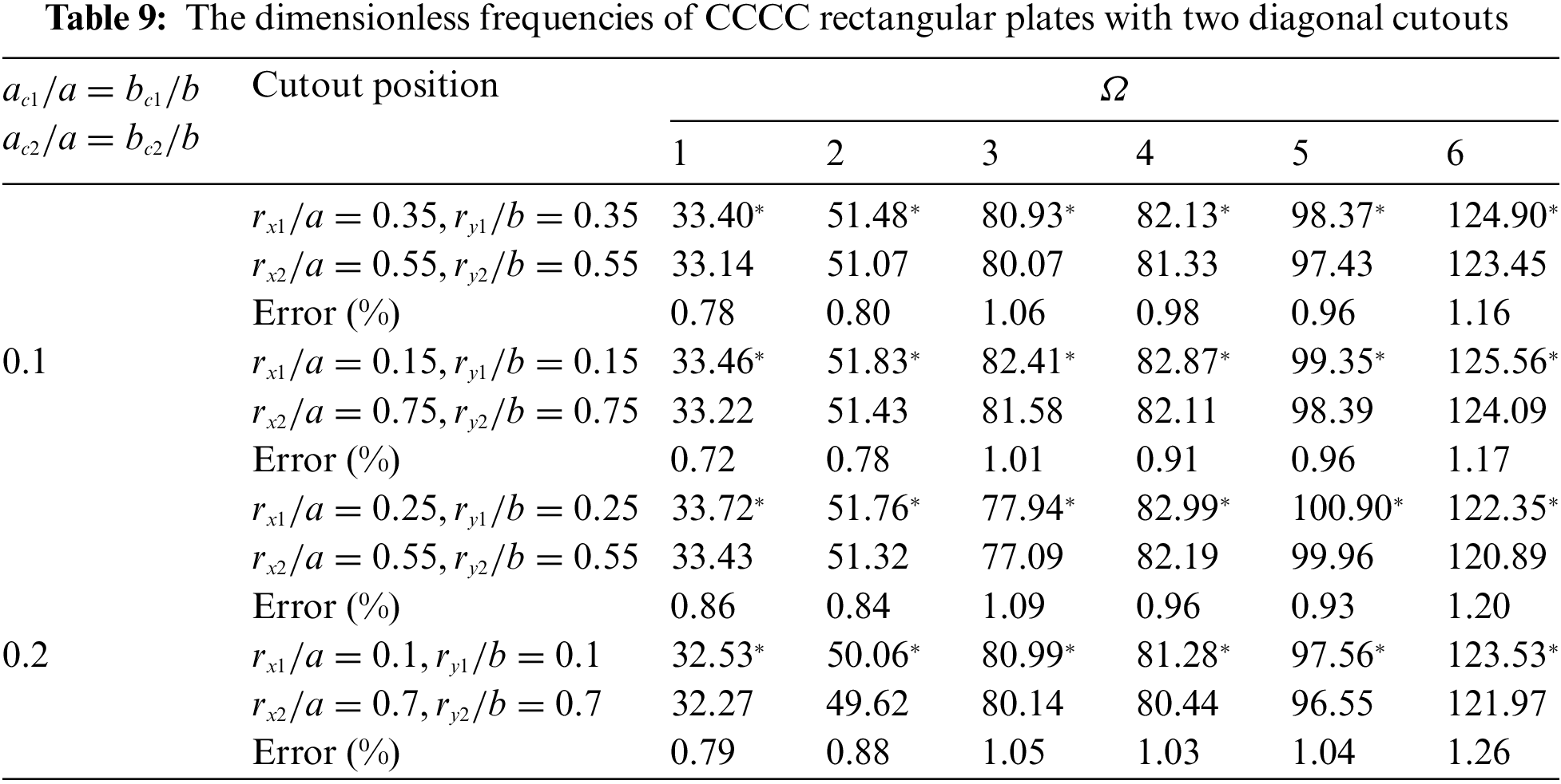

Figure 5: The mode shapes of rectangular plate with two horizontal cutouts under SSSS boundary condition by FEM
From Figs. 5–8, we can see that the shape of the vibration mode is consistent between the two methods; this further verifies the agreement between two methods. The accuracy of the results for a two-cutout rectangular plate with various cutout ratios under the SSSS and CCCC boundary conditions is apparent from the data. It can be shown that the calculation error increases as the cutout ratio increases. The present method adapts to solve the natural frequency of rectangular plate with two cutouts.

Figure 6: The mode shapes of rectangular plate with two horizontal cutouts under SSSS boundary condition by the present method

Figure 7: The mode shapes of rectangular plate with two diagonal cutouts under CCCC boundary condition by FEM

Figure 8: The mode shapes of rectangular plate with two diagonal cutouts under CCCC boundary condition by the present method
3.4 Calculation Efficiency Comparison in Different Coordinate System
In this section, we compare the solutions of rectangular plate with a cutout in the global coordinate system (RRM) and the independent coupling coordinate system (ICCM). For the case of a square plate with square cutout and SSSS boundary conditions, Figs. 9 and 10 provide the computational time trend by the two methods using Matlab for following cases: increasing truncated number, and increasing cutout ratio. In these simulations, the structure size is

Figure 9: Computational time vs. truncated number by two methods for square plate with one cutout

Figure 10: Computational time vs. cutout ratio by two methods for square plate with one cutout
As can be seen from Fig. 10, the calculation time of RRM method increases significantly as the cutout ratio increases, while the ICCM method remains fairly constant. This is due to that the integral limit of the RRM is increasing when integrating for the rectangular cutout, while the integral limit of the dimensionless ICCM for solving the rectangular cutout is constant. The solution speed does not change substantially as the size of the rectangular cutout varies.
For solving the rectangular plate with two cutouts, the computation time curve for truncated number for both methods is shown in Fig. 11. The structural parameters are:

Figure 11: Computational time vs. truncated number by two methods for square plate with two diagonal cutouts under CCCC boundary conditions
Comparing Figs. 9 and 11, the calculation time increases as the number of cutout increases, with the number of cutouts more greatly affecting the RRM method. By comparing the natural frequencies of the rectangular plates with cutouts under different truncated number, different cutout ratios and different cutout numbers, it can be concluded that the ICCM method has obvious computational advantages over the RRM method.
3.5 Calculation Accuracy Comparison in Different Coordinate System
In this section, the calculation accuracy results of different methods are given out. The comparison diagram of the first 50 natural frequencies of the square plate with center cutout under FFFF, SSSS and CCCC boundary conditions are demonstrate in Figs. 12–14. Three types of methods, FEM, ICCM and RRM are used to calculate the results. The structural parameters are:

Figure 12: Computational accuracy comparison of square plate with center cutout under FFFF boundary conditions

Figure 13: Computational accuracy comparison of square plate with center cutout under SSSS boundary conditions

Figure 14: Computational accuracy comparison of square plate with center cutout under CCCC boundary conditions
The modal experiment analysis of the free vibration of a rectangular plate with a cutout under free boundary conditions and clamped boundary conditions was conducted, and the single-point vibration measurement method was selected. The experiment considers some influencing vibration characteristics key factors of the rectangular plate with cutout, such as the cutout ratio and the plate thickness. It further serves to validate the accuracy of the present method with experimental results.
4.1 The Mode Experimental of Rectangular Plate with Eccentric Cutouts
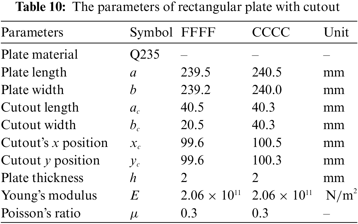
In this section, the experimental model is shown in Fig. 15. The four-edge free and clamped supported boundary conditions are considered. The free boundary conditions are simulated using a soft-rope suspension method, and the clamped supported boundary condition is simulated by uniformly fastening bolts along the four edges. The modal experimental system is shown in Fig. 16, and the structural and material parameters of the experimental apparatus are listed in Table 10. The first 6 natural frequencies are obtained by the single-point vibration pick-point under two types of boundary conditions; the results are presented in Table 11.

Figure 15: The experimental model of rectangular plate with cutout

Figure 16: The model experimental system

The % errors in Table 11 represent the relative deviation of the test results from the theoretical results. The data in Column 6 represents the error of the experimental results from the results generated from the finite element simulations while the results in column 7 represent the error of the results computed by the methods proposed in this paper (the truncated number is
4.2 Parameterized Analysis of Rectangular Plate with Cutouts
In this experiment, we conduct a parameterized analysis on a rectangular plate with a cutout under free boundary conditions; in this analysis, we take into consideration the hole ratio and plate thickness. The structural parameters of the rectangular plate with a cutout are: a = b = 240 mm, ac/a = 0.1, 0.3, 0.4, 0.5 and h = 4.5 mm, and the results for the first and second natural frequencies as the cutout ratio increases are presented in Fig. 17. In the plate thickness parameterization analysis, a = b = 240 mm, ac/a = 0.3, and h = 1.9 mm, 4.7 mm, 7.5 mm. The experimental and theoretical value curves of the rectangular plate with cutout are shown in Figure.

Figure 17: The natural frequency of rectangular plate with different cutout ratios,
From Figs. 17 and 18, we can see that the data curve of present method is in excellent agreement with the experimental results; this provides further evidence in support of the accuracy of the present method. Their trend very closely approximates the gradual decrease in frequency as cutout ratio increases. This is due to the fact that the main factor affecting the fundamental frequency of the plate with a cutout under free boundary conditions is its mass. As the cutout ratio increases, the whole mass matrix decreases, and then the frequency increases. Additionally, the natural frequency of the rectangular plate with cutout also increases with the increase of the plate thickness when the cutout ratio remains constant. Therefore, in the analysis of the model parameters of the rectangular plate with cutout, the size of cutout and the thickness of plate are important factors affecting the frequency of the rectangular plate with cutout.

Figure 18: The natural frequency of rectangular plate with one cutout with different thickness,
Based on the independent coordinate coupling system, this paper establishes the models of a rectangular plate with cutouts under elastic boundary conditions. The model of rectangular plate with cutouts is adapted to plates subjected to arbitrary elastic boundary conditions by the improved Fourier series, and the Rayleigh-Ritz energy method is used to deal with the relationship between the plate and the hole by means of energy subtraction. The frequency parameters are obtained by solving the matrix of the plate with cutouts by the Lagrangian equation. This method can satisfy the vibration solution of rectangular plate with holes under arbitrary elastic boundary conditions and produce highly accurate solutions. ICCM improves the computational efficiency by optimizing the integration domain of rectangular cutouts, shortens the time required for computation, and has obvious advantages when the cutout ratio increases or the number of holes increases.
The modal experiments of rectangular plate with a hole under free boundary conditions and clamped supported boundary conditions were conducted and, when compared with the theoretical results from the proposed method, provided evidence as to the accuracy of the method presented herein. In addition to the validation of the accuracy, the influence of the cutout size and thickness of rectangular plate under free boundary conditions was also examined. We observed that the natural frequencies of rectangular plate with holes decrease with the increase in cutout ratio, and that the frequencies also increase as thickness of the plate increases. The result of this work is beneficial to the engineering community as it provides us with an understanding of the vibration characteristics of rectangular plates with cutouts.
Funding Statement: All authors, except JS, acknowledge the support of this work by the National Natural Science Foundation of China (No. 51405096) and the Fundamental Research Funds for the Central Universities (HEUCF210710).
Conflicts of Interest: The authors declare that they have no conflicts of interest to report regarding the present study.
References
1. Sakiyama, T., Huang, M., Matsuda, H., Morita, C. (2003). Free vibration of orthotropic square plates with a square hole. Journal of Sound and Vibration, 259(1), 63–80. DOI 10.1006/jsvi.2002.5181. [Google Scholar] [CrossRef]
2. O’Boy, D. J., Krylov, V. V. (2016). Vibration of a rectangular plate with a central power-law profiled groove by the Rayleigh–Ritz method. Applied Acoustics, 104(4), 24–32. DOI 10.1016/j.apacoust.2015.10.018. [Google Scholar] [CrossRef]
3. Paramasivam, P. (1973). Free vibration of square plates with square openings. Journal of Sound and Vibration, 30(2), 173–178. DOI 10.1016/S0022-460X(73)80111-7. [Google Scholar] [CrossRef]
4. Aksu, G., Ali, R. (1976). Determination of dynamic characteristics of rectangular plates with cutouts using a finite difference formulation. Journal of Sound and Vibration, 44(1), 147–158. DOI 10.1016/0022-460X(76)90713-6. [Google Scholar] [CrossRef]
5. Nardini, D., Brebbia, C. A. (1983). A new approach to free vibration analysis using boundary elements. Applied Mathematical Modelling, 7(3), 157–162. DOI 10.1016/0307-904X(83)90003-3. [Google Scholar] [CrossRef]
6. Chen, Y. C., Chyanbin, H. (2014). Boundary element method for vibration analysis of two-dimensional anisotropic elastic solids containing holes, cracks or interfaces. Engineering Analysis with Boundary Elements, 40, 22–35. DOI 10.1016/j.enganabound.2013.11.013. [Google Scholar] [CrossRef]
7. Laura, P. A. A., Gutierrez, R. H. (1994). Analysis of vibrating rectangular plates with non-uniform boundary conditions by using the differential quadrature method. Journal of Sound and Vibration, 173(5), 702–706. DOI 10.1006/jsvi.1994.1255. [Google Scholar] [CrossRef]
8. Liu, G. R., Zhao, X., Dai, K. Y., Zhong, Z. H., Li, G. Y. et al. (2008). Static and free vibration analysis of laminated composite plates using the conforming radial point interpolation method. Composites Science and Technology, 68(2), 354–366. DOI 10.1016/j.compscitech.2007.07.014. [Google Scholar] [CrossRef]
9. Asemi, K., Ashrafi, H., Shariyat, M. (2016). Three-dimensional stress and free vibration analyses of functionally graded plates with circular holes by the use of the graded finite element method. Journal of Applied Mechanics and Technical Physics, 57(4), 690–700. DOI 10.1134/S0021894416040131. [Google Scholar] [CrossRef]
10. Kanak, K., Haldar, S. (2016). Free vibration analysis of rectangular plates with central cutout. Cogent Engineering, 3(1), 1–12. [Google Scholar]
11. Pavan Kishore, M. L., Bezawada, S., Raghu Kumar Reddy, B. C. (2017). Modal analysis of rectangular plate with central hole subjected to various end conditions. Materials Today: Proceedings, 4, 1653–1661. [Google Scholar]
12. Zhao, Y. B., Wei, G. W. (2002). DSC analysis of rectangular plates with non-uniform boundary conditions. Journal of Sound and Vibration, 255(2), 203–228. DOI 10.1006/jsvi.2001.4150. [Google Scholar] [CrossRef]
13. Laura, P. A. A., Laura, P. A., Cortinez, V. H. (1986). A note on transverse vibrations of a rectangular plate with a free, rectangular, corner cut-out. Journal of Sound and Vibration, 106(2), 187–192. DOI 10.1016/0022-460X(86)90311-1. [Google Scholar] [CrossRef]
14. Lee, H. P., Lim, S. P. (1992). Free vibration of isotropic and orthotropic square plates with square cutouts subjected to in-plane forces. Computers & Structures, 43(3), 431–437. DOI 10.1016/0045-7949(92)90276-6. [Google Scholar] [CrossRef]
15. Shufrin, I., Eisenberger, M. (2016). Semi-analytical modeling of cutouts in rectangular plates with variable thickness–Free vibration analysis. Applied Mathematical Modelling, 40(15), 6983– 7000. DOI 10.1016/j.apm.2016.02.020. [Google Scholar] [CrossRef]
16. Zhang, Y. P., Wang, C. M., Pedroso, D. M., Zhang, H. (2018). Extension of Hencky bar-net model for vibration analysis of rectangular plates with rectangular cutouts. Journal of Sound and Vibration, 432, 65–87. DOI 10.1016/j.jsv.2018.06.029. [Google Scholar] [CrossRef]
17. Chen Y. H., Jin G. Y., Liu Z. G. (2014). Flexural and in-plane vibration analysis of elastically restrained thin rectangular plate with cutout using Chebyshev–Lagrangian method. International Journal of Mechanical Sciences, 89, 264–278. DOI 10.1016/j.ijmecsci.2014.09.006. [Google Scholar] [CrossRef]
18. Huang, M., Sakiyama, T. (1999). Free vibration analysis of rectangular plates with variously-shaped holes. Journal of Sound and Vibration, 226(4), 769–786. DOI 10.1006/jsvi.1999.2313. [Google Scholar] [CrossRef]
19. Cho, D. S., Vladimir, N., Choi, T. M. (2014). Numerical procedure for the vibration analysis of arbitrarily constrained stiffened panels with openings. International Journal of Naval Architecture and Ocean Engineering, 6(4), 763–774. DOI 10.2478/IJNAOE-2013-0210. [Google Scholar] [CrossRef]
20. Cho, D. S., Kim, J. H., Choi, T. M., Kim, B. H., Vladimir, N. (2018). Free and forced vibration analysis of arbitrarily supported rectangular plate systems with attachments and openings. Engineering Structures, 171(5), 1036–10468. DOI 10.1016/j.engstruct.2017.12.032. [Google Scholar] [CrossRef]
21. Shi, S. X., Xiao, B., Jin, G. Y., Gao, C. (2018). Modeling and simulation of transverse free vibration analysis of a rectangular plate with cutouts using energy principles. Shock and Vibration, 2018, 1–16. DOI 10.1155/2018/9609745. [Google Scholar] [CrossRef]
22. Liu, Y. M., Lin, Z., Ding, H., Jin, G. Y., Yan, S. (2018). A modified Fourier–Ritz formulation for vibration analysis of arbitrarily restrained rectangular plate with cutouts. Shock and Vibration, 2018, 1–22. [Google Scholar]
23. Mochida, Y., Ilanko, S., Kennedy, D. (2017). Attaching negative structures to model cut-outs in the vibration analysis of structures. Computers & Structures, 184(3), 14–24. DOI 10.1016/j.compstruc.2017.02.003. [Google Scholar] [CrossRef]
24. Wang, G., Li, W. L., Feng, Z. H., Ni, J. F. (2019). A unified approach for predicting the free vibration of an elastically restrained plate with arbitrary holes. International Journal of Mechanical Sciences, 159(5), 267–277. DOI 10.1016/j.ijmecsci.2019.06.003. [Google Scholar] [CrossRef]
25. Liew, K. M., Hung, K. C., Lim, M. K. (1993). Method of domain decomposition in vibrations of mixed edge anisotropic plates. International Journal of Solids and Structures, 30(23), 3281–3301. DOI 10.1016/0020-7683(93)90114-M. [Google Scholar] [CrossRef]
26. Liew, K. M., Kitipornchai, S., Leung, A. Y. T., Lim, C. W. (2003). Analysis of the free vibration of rectangular plates with central cut-outs using the discrete Ritz method. International Journal of Mechanical Sciences, 45(5), 941–959. DOI 10.1016/S0020-7403(03)00109-7. [Google Scholar] [CrossRef]
27. Shufrin, I., Eisenberger, M. (2006). In-plane vibrations of rectangular plates with rectangular cutouts. Computational Methods in Engineering & Science, pp. 329–329. Berlin, Heidelberg: Springer. [Google Scholar]
28. Wang, M. H., Li, K., Qiu, Y. K., Li, T. Y., Zhu, X. (2017). Free vibration characteristics analysis of rectangular plate with rectangular opening based on Fourier series method. Chinese Journal of Ship Research, 12(4), 102–109. [Google Scholar]
29. Yuan, G. Q., Yu, Y., Wang, Z. L., Li, N., Cai, Y. L. et al. (2017). Free vibration analysis on structures of plates with hole reinforcement plates based on modified vibrational method. Computer Aided Engineering, 26(2), 58–64. [Google Scholar]
30. Jafari, M., Ardalani, E. (2017). Stress concentration in finite metallic plates with regular holes. International Journal of Mechanical Sciences, 106, 220–230. DOI 10.1016/j.ijmecsci.2015.12.022. [Google Scholar] [CrossRef]
31. Huang, D. T. (2013). Effects of constraint, circular cutout and in-plane loading on vibration of rectangular plates. International Journal of Mechanical Sciences, 68(4), 114–124. DOI 10.1016/j.ijmecsci.2013.01.005. [Google Scholar] [CrossRef]
32. Wagner, A., Gottfried, S. K. (2013). An efficient approach for the assembly of mass and stiffness matrices of structures with modifications. Journal of Sound and Vibration, 332(18), 4296–4307. DOI 10.1016/j.jsv.2013.03.003. [Google Scholar] [CrossRef]
33. Ali, R., Atwal, S. J. (1980). Prediction of natural frequencies of vibration of rectangular plates with rectangular cutouts. Computers & Structures, 12(6), 819–823. DOI 10.1016/0045-7949(80)90019-X. [Google Scholar] [CrossRef]
34. Avalos, D. R., Larrondo, H. A., Laura, P. A. A., Rossi, R. E. (1997). Transverse vibrations of simply supported rectangular plates with rectangular cutouts carrying an elastically mounted concentrated mass. Journal of Sound and Vibration, 202(4), 585–592. DOI 10.1006/jsvi.1996.0811. [Google Scholar] [CrossRef]
35. Larrondo H. A., Avalos D. R., Laura P. A. A., Rossi R. E. (2001). Vibrations of simply supported rectangular plates with varying thickness and same aspect ratio cutouts. Journal of Sound and Vibration, 244(4), 738–745. DOI 10.1006/jsvi.2000.3492. [Google Scholar] [CrossRef]
36. Masiá, U., Avalos, D. R., Laura, P. A. A. (2005). Displacement amplitudes and flexural moments for a rectangular plate with a rectangular cutout under a uniformly distributed static load. Journal of Sound and Vibration, 280(1), 433–442. DOI 10.1016/j.jsv.2004.01.044. [Google Scholar] [CrossRef]
37. Kwak, M. K., Han, S. B. (2007). Free vibration analysis of rectangular plate with a hole by means of independent coordinate coupling method. Journal of Sound and Vibration, 306(1), 12–30. DOI 10.1016/j.jsv.2007.05.041. [Google Scholar] [CrossRef]
38. Huang, B., Wang, J., Du, J. K., Ma, T. F., Guo, Y. et al. (2016). Vibration analysis of a specially orthotropic composite laminate with rectangular cutout using independent coordinate coupling method. Composite Structures, 150(12), 53–61. DOI 10.1016/j.compstruct.2016.05.010. [Google Scholar] [CrossRef]
39. Merneedi, A., Mohan, R. N., Subba, V. V. (2017). Free vibration analysis of a thin rectangular plate with multiple circular and rectangular cut-outs. Journal of Mechanical Science and Technology, 31(11), 5185– 5202. DOI 10.1007/s12206-017-1012-5. [Google Scholar] [CrossRef]
40. Guo, Y., Jiang, Y. N., Huang, B. (2019). Independent coordinate coupling method for vibration analysis of a functionally graded carbon nanotube-reinforced plate with central hole. Advances in Mechanical Engineering, 11(8), 1–14. DOI 10.1177/1687814019872924. [Google Scholar] [CrossRef]
41. Avalos, D. R., Laura, P. A. A. (2003). Transverse vibrations of simply supported rectangular plates with two rectangular cutouts. Journal of Sound and Vibration, 267(4), 967–977. DOI 10.1016/S0022-460X(03)00217-7. [Google Scholar] [CrossRef]
42. Xue, K., Huang, W., Li, Q. (2020). Three-dimensional vibration analysis of laminated composite rectangular plate with cutouts. Materials, 13(14), 1–23. DOI 10.3390/ma13143113. [Google Scholar] [CrossRef]
43. Nie, R., Li, T. Y., Zhu, X., Guo, W. J. (2018). Free vibration analysis of rectangular thin plate with multiple openings under general boundary conditions. 47th International Congress and Exposition on Noise Control Engineering: Impact of Noise Control Engineering, pp. 1–9. Chicago, IL. [Google Scholar]
Cite This Article
 Copyright © 2023 The Author(s). Published by Tech Science Press.
This work is licensed under a Creative Commons Attribution 4.0 International License , which permits unrestricted use, distribution, and reproduction in any medium, provided the original work is properly cited.
 Downloads
 Citation Tools