
 Submit a Paper
 Propose a Special lssue
 Open Access
ARTICLE
Vibration and Sound Radiation of Cylindrical Shell Covered with a Skin Made of Micro Floating Raft Arrays Excited by Turbulence
1 College of Mechanical and Electrical Engineering, Harbin Engineering University, Harbin, 150001, China
2 Shanghai Marine Equipment Research Institute, Shanghai, 200031, China
* Corresponding Author: Dan Zhao. Email:
(This article belongs to the Special Issue: Computer Modeling in Ocean Engineering Structure and Mechanical Equipment)
Computer Modeling in Engineering & Sciences 2023, 134(3), 2041-2055. https://doi.org/10.32604/cmes.2022.021026
Received 23 December 2021; Accepted 26 April 2022; Issue published 20 September 2022
 View Full Text
 Download PDF
Abstract
To reduce the vibration and sound radiation of underwater cylindrical shells, a skin composed of micro floating raft arrays and a compliant wall is proposed in this paper. A vibroacoustic coupling model of a finite cylindrical shell covered with this skin for the case of turbulence excitation is established based on the shell theories of Donnell. The model is solved with the modal superposition method to investigate the effects of the structural parameters of micro floating raft elements on the performance of reducing vibration and sound radiation of the cylindrical shell of this skin. The results indicate that increasing the stiffness ratio, damping ratio, mass ratio, or decreasing the interval between micro floating raft elements can improve the vibration and sound radiation reduction performance of this skin over the frequency range 0~2000 Hz. Moreover, the mean quadratic velocity level and sound radiation power level of the finite cylindrical shell with this skin can be reduced by 12.00 dB and 9.65 dB respectively compared to the finite cylindrical shell with homogeneous viscoelastic coating in the frequency range from 0~2000 Hz, implying a favorable performance of this skin for reducing the vibration and sound radiation of cylindrical shells.Keywords
The vibration and sound radiation of underwater cylindrical shells are always the main research contents in mechanics and acoustics because the cylindrical shell is the main structure of the great majority of underwater vehicles [1]. In order to reduce the vibration and sound radiation of the cylindrical shell, active vibration control [2,3], dynamic absorbers [4], circumferential ribs [5], lateral reinforced plates [6] and compliant layer [7,8] have been employed in the past. Among them, a compliant layer is widely used due to the stronger plasticity in structural design and lower cost in manufacturing. Laulagnet et al. [9] presented a mathematical model in order to investigate the sound radiation from a finite cylindrical shell covered with a compliant layer, indicating that a compliant layer with reasonable stiffness can reduce the radiated power in a large frequency domain. Liu et al. [10] focused on the vibration and acoustic radiation of a finite cylindrical shell, which is partially covered with circumferentially laid compliant layers and immersed in an infinite heavy fluid medium. It is found that the axisymmetry of the coatings has an effect on the radiated power of the partially covered shell. Huang et al. [11] presented an optimal design of acoustic coating with complex-shaped cavities based on a combining use of the analytical vibroacoustic model and a differential evolution algorithm to explore the better performance of sound radiation reduction. As can be seen, the compliant layer is an effective method to control the vibration and sound radiation of cylindrical shells and the optimal design of the compliant layer is one of the major research directions.
A floating raft isolation system has been widely applied to reduce the multi-point vibration of power units inside the ship [12–14]. Li et al. [15] analyzed the power flow of a floating raft isolation system by using the Green function, demonstrating a satisfactory vibration-reduction effect of the floating raft system. Liu et al. [16] studied the influence of the floating raft isolation system on the vibration characteristics of the marine pump, indicating the maximum vibration intensity of the pump is reduced by 88% after installing the floating raft damping system. Li et al. [17] focused on the effects of the geometric parameters of a floating raft on isolation performance. The results show that the structural parameters of middle mass have an impact on isolation performance. Fang et al. [18] investigated the vibration reduction characteristic of the floating raft with a periodic structure, demonstrating the same quality of the periodic floating raft has a better isolation effect than that of the single floating raft.
Considering the limitations of the current vibration and sound radiation reduction technology and the similarity between the multi-point excitation on the floating raft system and the turbulence excitation, a skin made of micro floating raft arrays and compliant layer (will be abbreviated as floating raft skin in following) is proposed. The structure is shown in Fig. 1, where the upper layer is the compliant wall and the lower layer is micro floating raft arrays.
Figure 1: The structure of a skin made of micro floating raft arrays
Consisting of a compliant wall and micro floating raft arrays, the floating raft skin has several adjustable parameters such as stiffness ratio and damping ratio. It is expected to have a better performance in controlling turbulent coherent structures, so as to reduce vibration and sound radiation of underwater cylindrical. The micro floating raft element not only can absorb and attenuate elastic wave directly, but also can form different periodic structure due to its adjustable interval and size, so that changing the noise suppression bands and bandwidths of the floating raft skin and realizing the function of reducing vibration and sound radiation. The proposal of this novel skin not only is helpful to improve the vibration and sound radiation performance of underwater cylindrical, but also makes a beneficial exploration in related theory and application.
The remainding part of this paper is organized as follows. In Section 2, the mathematical model of a finite cylindrical shell covered with floating raft skin is established based on the shell theories of Donnell and it is solved with modal superposition method. In Section 3, the relationship between the performance of the floating raft skin to reduce the vibration and sound radiation of cylindrical shells and the structural parameters of micro floating raft elements is investigated. The difference in the performance for reducing vibration and sound radiation of cylindrical shells between the floating raft skin and homogeneous viscoelastic coating is also discussed in Section 3. Finally, the conclusion of this paper is drawn in Section 4.
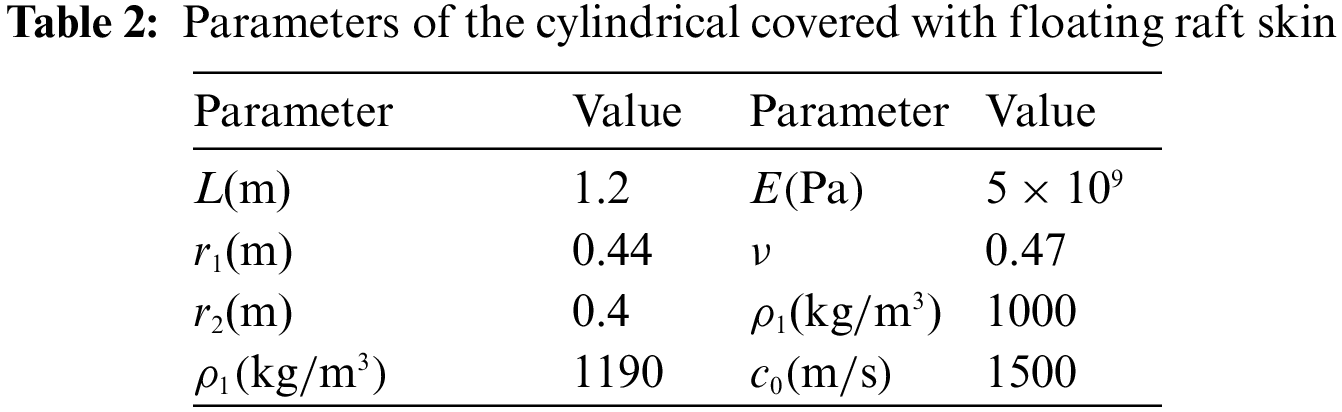
In order to investigate the vibration and the sound radiation performance of the floating raft skin, a mathematical model of the cylindrical shell covered with the floating raft skin should be established. Here, the cylindrical shell covered with the floating raft skin is shown in Fig. 2, whose thickness divided by radius is less than 5%, is thin with radius
Figure 2: Cylindrical shell covered with the floating raft skin
Based on the shell theories of Donnell [19], the vibration equation of the compliant wall can be set up
where
The displacements of the compliant wall are expanded with the modal expansion method, as follows:
where m and n are the axial and circumferential mode number, respectively;
Similarly, the support force of micro floating raft array, the radial pressure of the internal fluid, the radial pressure of the external fluid and the excitation of turbulence are expanded, as follows:
where
Substituting Eqs. (2) and (3) into Eq. (1), the modal vibro-acoustic coupling equation of the compliant wall is formulated as follows:
where the matrix
when n = 1,2,3…,
when n = 0,
Solving the Eq. (4) by separating variable methods leads to the radial modal vibration equation of the compliant wall
where
To attain the numerical solution of Eq. (5), the coefficients
where
The bearing condition of the j-th compliant wall element is shown in Fig. 3, where
Figure 3: The j-th compliant wall corresponding to micro floating raft element
The dynamic equation of the j-th compliant wall element is
The support force of micro floating raft element can be solved according to Eq. (7)
The support force of the micro floating raft array equals the sum of the support forces of micro floating raft elements, as shown as follows:
where
Combining Eq. (9) with Eq. (6), the coefficient of the support force of the micro floating raft array is
where
The compliant wall vibrates due to the excitation of turbulence, leading to the vibration of the internal fluid. The radial pressure of internal fluid satisfies the Helmholtz equation [20].
where
It can be seen from Eq. (3)
Substituting Eq. (13) into Eq. (12), the formal solution of
where
The boundary condition of the internal fluid radial pressure is shown as followes:
Substituting Eq. (14) into Eq. (15) can we solve the coefficients
where
The radial pressure of the external fluid at
By the method of separation of variables and the x-dimensional Fourier transform, the equation of
The formal solution of
where
The radiation pressure of external fluid satisfies the boundary condition
where
Substituting Eq. (20) into Eq. (21), and carries on the Fourier transform treatment, so
where
The turbulent excitation is expressed by Corcos model
where the specific parameter can be found in Ko [21].
Inverse Fourier transform is used for
Substituting Eqs. (11), (17), (23) and (25) into Eq. (5), the modal velocity solution of the compliant wall is obtained. Furthermore, the mean quadratic velocity and the sound radiation power of the compliant wall can be represented as
where S is the surface area of the compliant wall; “
The mean of quadratic velocity level and sound radiation power level is defined as
where
2.2 Convergence Study of the Axial and Circumferential Mode Number
Figs. 4a and 4b show the curves of the mean quadratic velocity level and the sound radiation power level with the frequency under different truncation values of the axial mode number, respectively. It can be seen that m = 15 is enough to guarantee the accuracy in the frequency range from 0 to 2000 Hz.
Figure 4: Result of the mean quadratic velocity level and the sound radiation power level under different truncation values of the axial mode number
Figs. 5a and 5b show the curves of the mean quadratic velocity level and the sound radiation power level with the frequency under different truncation values of the circumferential mode number, respectively. It could be noted that n = 20 is enough to guarantee the accuracy in the 0–2000 Hz scope.
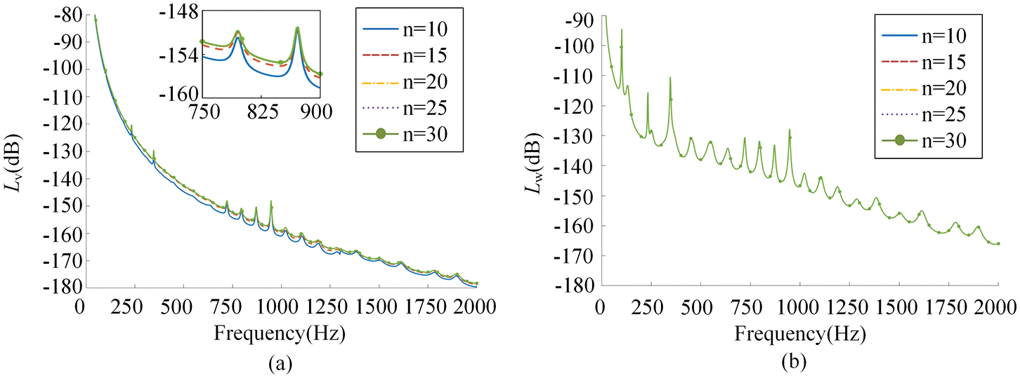
Figure 5: Result of the mean quadratic velocity level and the sound radiation power level under different truncation values of the axial mode number
2.3 Validation of the Algorithm
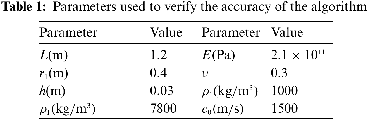
In order to verify the accuracy of the algorithm, the sound radiation power level in Guo et al. [22] is calculated by using our method. The parameters used are shown in Table 1.
The excitation force concentrates at the locations of
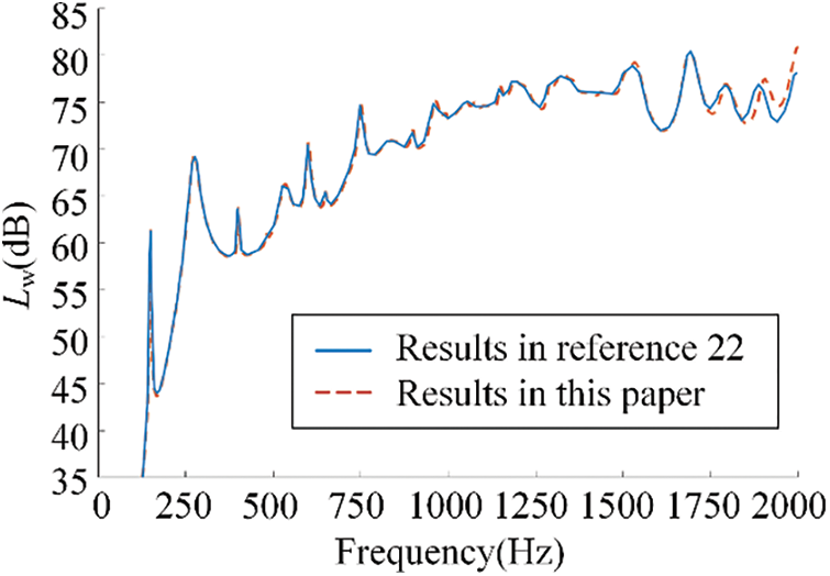
Figure 6: Result comparison with [22]
In Fig. 6, we can find the curve trend of this paper is in good agreement with Guo. The error in the high frequency band is caused by the different shell motion theories used in the two papers. The shell theories used in Guo are proposed by Flugge, but Donnell shell theories are used in this paper.
The curves of mean quadratic velocity and sound radiation power with the coefficients of the interval micro floating raft elements
3.1 The Effect of Micro Floating Raft Element Interval on the Vibration and Sound Radiation Reduction Performance of the Floating Raft Skin
Increase in
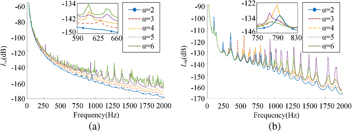
Figure 7: The influence of different micro floating raft element interval on (a) mean quadratic velocity level and (b) sound radiation power level
From Fig. 7a, the value of the mean quadratic velocity level
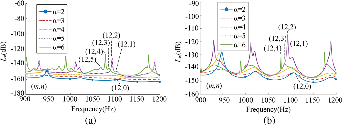
Figure 8: The modes of one formant corresponding to different micro floating raft element interval
3.2 The Effect of Stiffness Ratio on the Vibration and Sound Radiation Reduction Performance of the Floating Raft Skin
The stiffness ratio
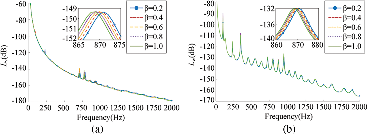
Figure 9: The influence of different stiffness ratio on (a) mean quadratic velocity level and (b) sound radiation power level
It could be noted in Fig. 9 that there is no obvious difference in the trend of the curves of the mean quadratic velocity level and the sound radiation power level with various stiffness ratio, indicating that the vibration and sound radiation reduction performance of the floating raft skin is hardly changed by changing stiffness ratio. The reason behind these results is that the modal velocity is decided by the sum of the impedances, but only the imaginary part of the additional impedance of micro floating raft array
3.3 The Effect of Damping Ratio on the Vibration and Sound Radiation Reduction Performance of the Floating Raft Skin
Selecting
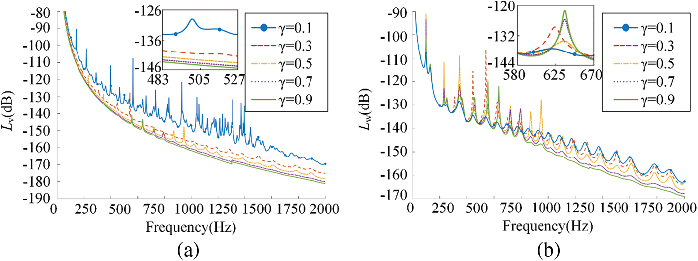
Figure 10: The influence of different damping ratio on (a) mean quadratic velocity level and (b) sound radiation power level
As shown in Fig. 10a, the mean quadratic velocity level decreases with the increase of the damping ratio
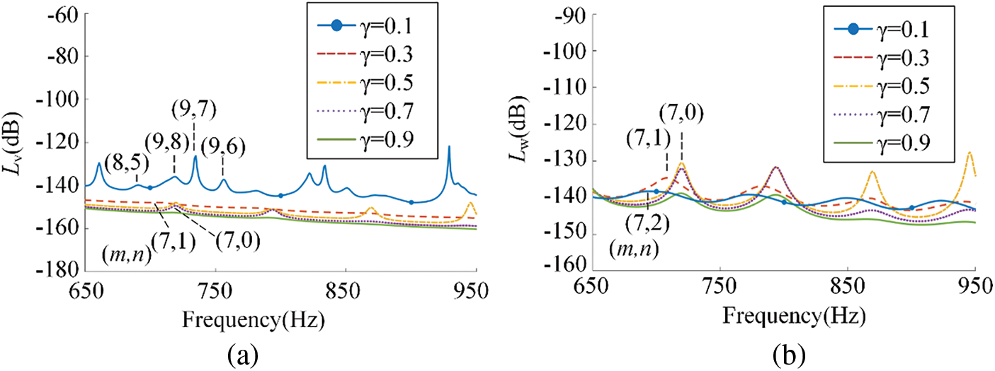
Figure 11: The modes of one formant corresponding to different damping ratio
3.4 The Effect of Mass Ratio on the Vibration and Sound Radiation Reduction Performance of the Floating Raft Skin
When
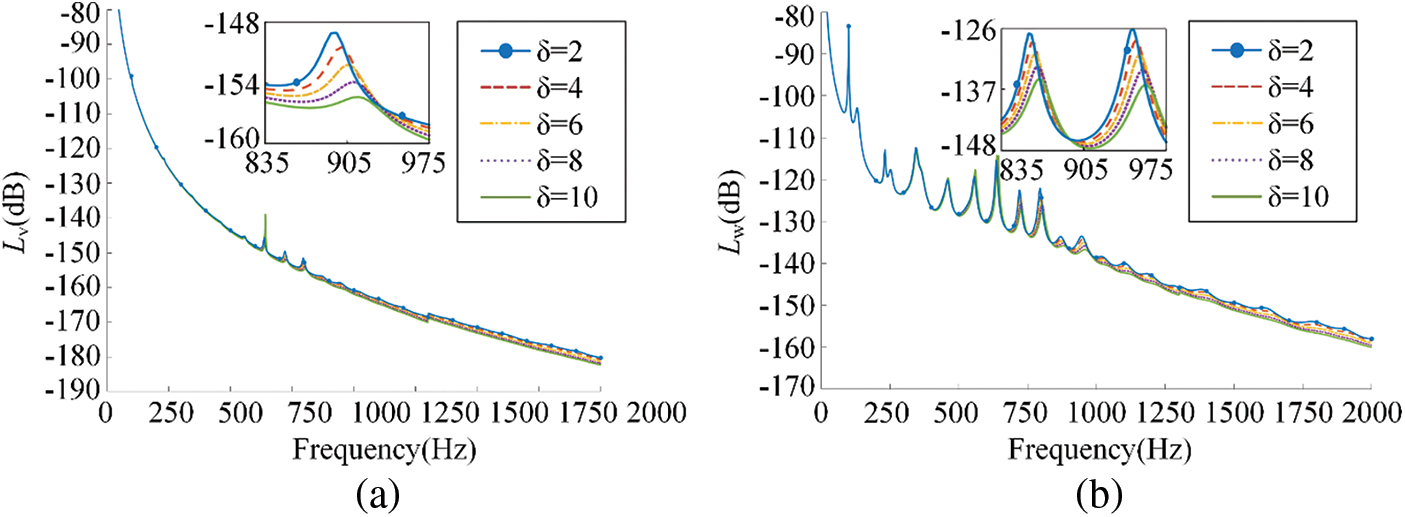
Figure 12: The influence of different mass ratio on (a) mean quadratic velocity level and (b) sound radiation power level
It can be seen from Fig. 12, the mean quadratic velocity level and the sound radiation power level decrease with the increase of mass ratio
3.5 Comparison in Vibration and Sound Radiation Reduction Performance with Homogeneous Viscoelastic Coating
In order to further analyze the vibration and sound radiation reduction performance of the floating raft skin, selecting parameters:
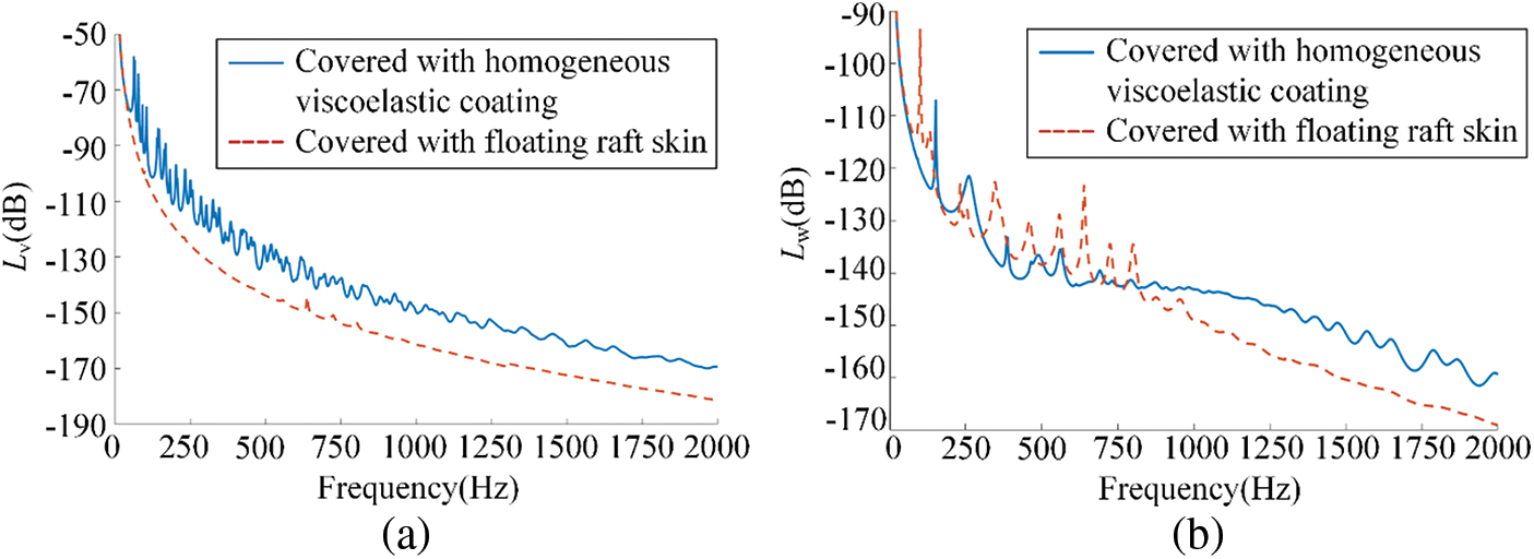
Figure 13: The vibration and sound radiation performance of two kinds of coating
As shown in Fig. 13, in the frequency range with 0–2000 Hz, the average mean quadratic velocity level of the floating raft skin is reduced by 12.00 dB and the average mean quadratic velocity level of the floating raft skin is reduced by 9.65 dB compared with homogeneous viscoelastic coating. This shows that the floating raft skin perform better in vibration and sound radiation reduction than the homogeneous viscoelastic coating in the frequency range from 0 to 2000 Hz.
In this paper, a skin made of micro floating raft arrays is proposed, which is consisted of a floating raft system and a compliant wall. A mathematical model of the cylindrical shell covered with the floating raft skin is established, and the influence of various structural parameters on the compliant wall in the vibration and sound radiation of the shell is illustrated. The results show that increasing the stiffness ratio, damping ratio, mass ratio or decreasing the micro floating raft element interval can improve the vibration and noise reduction performance of the micro floating skin. Moreover, the floating raft skin can reduce the mean quadratic velocity level and sound radiation power level by 12.00 dB and 9.65 dB more respectively compared to the counterpart with homogeneous viscoelastic coating, leading to a favorable performance for reducing the hydrodynamic noise.
Funding Statement: The work is supported by the National Natural Science Foundation of China (Grant Nos. 51775123, 52075111) and the Fundamental Research Funds for the Central Universities (Grant No. 3072021CF0702).
Conflicts of Interest: The authors declare that they have no conflicts of interest to report regarding the present study.
References
1. Zou, M. S., Jiang, L. W., Liu, S. X. (2018). Underwater acoustic radiation by structures arbitrarily covered with acoustic coatings. Journal of Sound and Vibration, 443, 743–768. DOI 10.1016/j.jsv.2018.12.017. [Google Scholar] [CrossRef]
2. Kim, H., Sohn, J., Jeon, J., Choi, S. (2013). Reduction of the radiating sound of a submerged finite cylindrical shell structure by active vibration control. Sensors, 13(2), 2131–2147. DOI 10.3390/s130202131. [Google Scholar] [CrossRef]
3. Huang, X. C., Zhang, Z. Y., Zhang, Z. H., Hua, H. X. (2012). Multi-channel active vibration isolation for the control of underwater sound radiation from a stiffened cylindrical structure: A numerical study. Journal of Vibration & Acoustics, 134(1), 11012. DOI 10.1115/1.4004684. [Google Scholar] [CrossRef]
4. Cao, Y. P., Zhang, W. P. (2007). Using dynamic absorbers to reduce underwater structural noise due to longitudinal vibration of shafting. Journal of Harbin Engineering University, 28(7), 747–751. [Google Scholar]
5. Liu, X. O., Yin, S. P., Yan, F. H. (2006). Underwater vibration modal calculation of the ring-stiffened cylindrical shell with MSC Nastran. Computer Aided Engineering, 124–127. [Google Scholar]
6. Wang, L. C., Zhou, Q. D. (2013). Effects of lateral reinforced plates on underwater vibro-acoustic features of ring-stiffened cylindrical shells. Chinese Journal of Ship Research, 8(2), 84–89. [Google Scholar]
7. Kim, E. I., Lee, J. S., Kim, Y. Y. (2006). One-dimensional topology optimization for transmission loss maximization of multi-layered acoustic foams. The Fourth China-Japan-Korea Joint Symposium on Optimization of Structural and Mechanical Systems. China: Dalian University of Technology Press. [Google Scholar]
8. Jin, G. Y., Shi, K. K., Ye, T. G., Zhou, J. L., Yin, Y. W. (2020). Sound absorption behaviors of metamaterials with periodic multi-resonator and voids in water. Applied Acoustics, 166(3), 107351. DOI 10.1016/j.apacoust.2020.107351. [Google Scholar] [CrossRef]
9. Laulagnet, B., Guyader, J. L. (1995). Sound radiation from finite cylindrical shells, partially coated with longitudinal strip of compliant layer. Journal of Sound and Vibration, 186(5), 723–742. DOI 10.1006/jsvi.1995.0485. [Google Scholar] [CrossRef]
10. Liu, S., Zou, M. S., Jiang, L. W., Zhao, X. Y. (2018). Vibratory response and acoustic radiation of a finite cylindrical shell partially covered with circumferential compliant layers. Applied Acoustics, 141, 188–197. DOI 10.1016/j.apacoust.2018.07.012. [Google Scholar] [CrossRef]
11. Huang, L. Z., Xiao, Y., Wen, J. H., Zhang, H., Wen, X. S. (2018). Optimization of decoupling performance of underwater acoustic coating with cavities via equivalent fluid model. Journal of Sound and Vibration, 426, 244–257. DOI 10.1016/j.jsv.2018.04.024. [Google Scholar] [CrossRef]
12. Li, Y. L., Xu, D. L. (2018). Force transmissibility of floating raft systems with quasi-zero-stiffness isolators. Journal of Vibration and Control, 24(16), 3608–3616. DOI 10.1177/1077546317708460. [Google Scholar] [CrossRef]
13. Ma, Y. T., Zhou, Y. (2008). Summary of floating raft system. Ship Science and Technology, 30(4), 22–26. [Google Scholar]
14. Song, C. S., Xiao, Y., Yu, C. C., Xu, W. (2017). H∞ active control of frequency-varying disturbances in a main engine on the floating raft vibration isolation system. Journal of Low Frequency Noise, Vibration and Active Control, 1–17. DOI 10.1177/1461348417725944. [Google Scholar] [CrossRef]
15. Li, T. Y., Zhang, X. M., Zuo, Y. T., Xu, M. B. (1997). Structural power flow analysis for a floating raft isolation system consisting of constrained damped beams. Journal of Sound and Vibration, 202(1), 47–54. DOI 10.1006/jsvi.1996.0788. [Google Scholar] [CrossRef]
16. Liu, H. L., Ma, Q. J., Li, Y., Wang, K. (2020). Vibration control of a marine centrifugal pump using floating raft isolation system. Journal of Low Frequency Noise Vibration and Active Control, 39(2), 382–392. DOI 10.1177/1461348419843024. [Google Scholar] [CrossRef]
17. Li, S. D., Liu, Y. (2017). Effect analysis of geometric parameters of floating raft on isolation performance. Chinese Journal of Ship Research, 12(6), 108–113+119. [Google Scholar]
18. Fang, Y. Y., Zuo, Y. Y., Xia, Z. W. (2018). Study on design method and vibration reduction characteristic of floating raft with periodic structure. IOP Conference Series Materials Science and Engineering, 322(4), 042025. DOI 10.1088/1757-899X/322/4/042025. [Google Scholar] [CrossRef]
19. Donnell, L. H. (1933). Stability of thin-walled tubes under torsion. N. A. C. A. Report, 479. [Google Scholar]
20. Junger, M. C., Feit, D. (1972). Sound, structures, and their interaction. USA: MIT Press. [Google Scholar]
21. Ko, S. H. (1993). Performance of various shapes of hydrophones in the reduction of turbulent flow noise. The Journal of the Acoustical Society of America, 93(3), 1293–1299. DOI 10.1121/1.405414. [Google Scholar] [CrossRef]
22. Guo, Y. J., Wang, H. J., Yi, H. (2019). Vibration and sound radiation of submerged finite cylindrical shells with pre-stress. Scientific Reports, 9(1), 11307. DOI 10.1038/s41598-019-47809-x. [Google Scholar] [CrossRef]
23. Tao, M., Fan, J., Tang, W. L. (2008). The characteristics of sound radiation from a cylindrical shell coated with multiple compliant layers. Shengxue Xuebao/Acta Acustica, 33(3), 220–225. [Google Scholar]
Cite This Article
 Copyright © 2023 The Author(s). Published by Tech Science Press.
This work is licensed under a Creative Commons Attribution 4.0 International License , which permits unrestricted use, distribution, and reproduction in any medium, provided the original work is properly cited.
 Downloads
 Citation Tools