 Open Access
ARTICLE
Topology Optimization of Sound-Absorbing Materials for Two-Dimensional Acoustic Problems Using Isogeometric Boundary Element Method
1 College of Architecture and Civil Engineering, Xinyang Normal University, Xinyang, 464000, China
2 College of Mechanics and Materials, Hohai University, Nanjing, 211100, China
* Corresponding Author: Xiaowei Shen. Email:
(This article belongs to the Special Issue: Recent Advance of the Isogeometric Boundary Element Method and its Applications)
Computer Modeling in Engineering & Sciences 2023, 134(2), 981-1003. https://doi.org/10.32604/cmes.2022.021641
Received 25 January 2022; Accepted 17 March 2022; Issue published 31 August 2022
Abstract
In this work, an acoustic topology optimization method for structural surface design covered by porous materials is proposed. The analysis of acoustic problems is performed using the isogeometric boundary element method. Taking the element density of porous materials as the design variable, the volume of porous materials as the constraint, and the minimum sound pressure or maximum scattered sound power as the design goal, the topology optimization is carried out by solid isotropic material with penalization (SIMP) method. To get a limpid 0–1 distribution, a smoothing Heaviside-like function is proposed. To obtain the gradient value of the objective function, a sensitivity analysis method based on the adjoint variable method (AVM) is proposed. To find the optimal solution, the optimization problems are solved by the method of moving asymptotes (MMA) based on gradient information. Numerical examples verify the effectiveness of the proposed topology optimization method in the optimization process of two-dimensional acoustic problems. Furthermore, the optimal distribution of sound-absorbing materials is highly frequency-dependent and usually needs to be performed within a frequency band.Keywords
With the rapid development of road and railway construction and the rapid increase in car ownership, noise pollution is increasingly affecting our lives and health, which has become a worldwide problem. Researchers have introduced several methods for optimizing design, including a range of work on sound barriers [1–3], automobiles [4–6], buildings [7,8] and mufflers [9,10]. At present, porous materials have been widely used in the field of noise control because of their excellent sound absorption characteristics [11–15]. Considering various constraints, including economy, laying porous materials in certain areas is an effective method. Therefore, it is necessary to obtain the partial optimal distribution of porous materials under given constraints. This leads to a series of problems about topology optimization [16–18]. Since Bendsøe et al. [19] proposed the topology optimization method, which has become an important engineering tool. Many researchers have also introduced topology optimization techniques into acoustic analysis [20–23]. Topology optimization of the distribution of porous materials in two-dimensional muffler models using the finite element method (FEM) was first proposed by Yoon et al. [24], and the framework was extended to the topology optimization of acoustic barrier surfaces composed of both rigid and porous materials by Kim et al. [1]. However, it is a typical semi-infinite domain external sound field problem, and it is difficult to numerically simulate the performance of the noise barrier by the FEM. As we all know, the boundary element method (BEM) is superior to the FEM when solving sound field problems in infinite/semi-infinite domains because of its advantages such as high accuracy and automatic mesh generation [25–28]. However, as the amount of computation increases, the process of meshing will consume a lot of costs, which makes the transition process from CAD to CAE very cumbersome. When encountering dynamic computation processes, the mesh needs to be constantly reconstructed. In isogeometric analysis (IGA) [29,30], the spline basis function commonly used in CAD is used to replace the Lagrangian basis function in the traditional interpolation form, which successfully eliminates the transformation process from CAD to CAE [31,32]. At the same time, geometric errors are eliminated and therefore the accuracy of the calculation is significantly improved. The BEM can be well combined with IGA due to the discrete nature of BEM, that is, the isogeometric boundary element method (IGABEM) [33–35]. IGABEM not only retains the advantages of the BEM such as dimensionality reduction and high accuracy but also enables numerical analysis to be carried out directly from CAD, which greatly improves calculation efficiency [36–39]. Therefore, IGABEM is chosen for the optimal analysis of acoustic problems in this work.
As we all know, the solution methods of optimization problems are mainly the non-gradient method and the gradient method. The non-gradient method has no use for gradient information, i.e., the derivatives of the objective and constraint function in regard to the design variables. Moreover, the non-gradient algorithm can achieve better solutions for problems with fewer degrees of freedom such as dimensional optimization, while the solution efficiency is very low for problems with a large number of degrees of freedom such as topology optimization. However, the gradient algorithm is well-efficient for large-scale problems, thereby, most extension optimization problems are solved by the gradient algorithm. From an engineering point of view, the gradient method is obviously more practical because it can save the cost. In addition, the gradient algorithm requires gradient information (i.e., sensitivity information) of the objective function and constraints in regard to the design variables to guide the iterative update of the design variables during optimization. Therefore, it is necessary to solve the gradient value of the objective function. The finite difference method (FDM) [40–42] performs a differential operation on each design variable to get complete gradient information. Therefore, its computational efficiency is highly dependent on the number of design variables. In addition, the accuracy of FDM depends largely on the step length and the computational accuracy of the objective function itself. Too large or too small a step length will affect the results of the calculation, and the stability is difficult to be guaranteed in the actual calculation. Compared with FDM, the direct differentiation method (DDM) [43–45] uses chain differentiation rules to get the gradient value for the objective function on the basis of intermediate gradient values. The DDM is easy to understand and highly stable, so this method is widely used for sensitivity analysis. However, as the number of design variables increases, DDM requires a computer with high storage capacity. In summary, neither FDM nor DDM applies to problems with a large number of degrees of freedom. Compare with DDM, the adjoint variable method (AVM) [46,47] can avoid the calculation of gradient values for intermediate variables by introducing adjoint equations. And the adjoint equations are independent of the design variables. Therefore, AVM tends to be less costly and more suitable for solving optimization problems with a large number of design variables. Numerous scholars have introduced the AVM into structural-acoustic sensitivity analysis, and have achieved remarkable results [48–50].
Among the various methods of topology optimization of continuums, the variable density method is the most widely used. Because this method makes the original
The rest of the work is arranged as follows. NURBS is briefly introduced into Section 2. Section 3 is the basic formulations for BEM. Section 4 describes the whole optimization process, including the creation of the topology optimization model, material interpolation method, the analysis of the acoustic sensitivity and updating schemes for design variables. Section 5 provides several numerical examples to verify the availability of the proposed optimization procedure. Section 6 elaborates the conclusions of this work.
Using the concept of the knot vector, the B-spline basis function
where the knot vector is denoted as
Non-Uniform Rational B-Splines (NURBS) [2,31] developed from B-splines, is an important geometric modeling technique in CAD and is considered as an industry standard. Therefore, all geometries in this work are represented by NURBS. The NURBS curve
where NURBS basis functions
with
where
3 BEM for 2D Acoustic Analysis
The Helmholtz governing differential equation based on sound pressure is shown as Eq. (6)
where
where
where
For 2D half space problems, the kernel functions can be expressed as Eq. (9)
in which
In this work, we utilize NURBS to discretize the boudary of the structure. The Eq. (7) are discretized into matrix form as Eq. (10)
where coefficient matrices
where
where coefficient matrices
4 Topology Optimization Model Based on BEM
4.1 The Creation of Topology Optimization Model
The topology optimization problem that obeys the material volume constraint can generally be expressed as Eq. (13)
where
Taking into account the impedance boundary condition
in which
where
4.2 Material Interpolation Scheme
To solve the problems that the design variables between 0 and 1 are discrete, the relationship between the normalized surface admittance value
in which the admittance of the
in which
4.3 The Analysis of Acoustic Sensitivity
In the previous section, the admittance has become a continuous function, therefore the optimization problem can be solved using gradient-based algorithm. In this work, AVM is used for the analysis of acoustic sensitivity. Firstly, the derivative of the objective function regarding the design variable is divided into three parts as Eq. (18)
where
where
Actually
Substituting the Eq. (21) into the Eq. (18) and letting the adjoint vector satisfy the following adjoint equation:
After solving the Eq. (22) to obtain the adjoint vectors, the derivative of the objective function regarding any design variable can be expressed as Eq. (23)
In acoustic optimization, a number of different objective functions can be chosen, including sound pressure value, radiated power and transmission loss. In this work, two different objective functions are used for the optimization analysis.
Objective function 1: To obtain the minimum sound pressure, the objective function is shown as Eq. (24)
Objective function 2: To obtain the maximum the absorbed sound power of the sound-absorbing materials, the objective function is shown as Eq. (25)
where
4.4 Design Variable Updating Method
In this work, the topology optimization problem is solved using MMA [57]. The flowchart of topology optimization process based on acoustic IGABEM is shown in Fig. 1, the convergence condition is as Eq. (26)
where
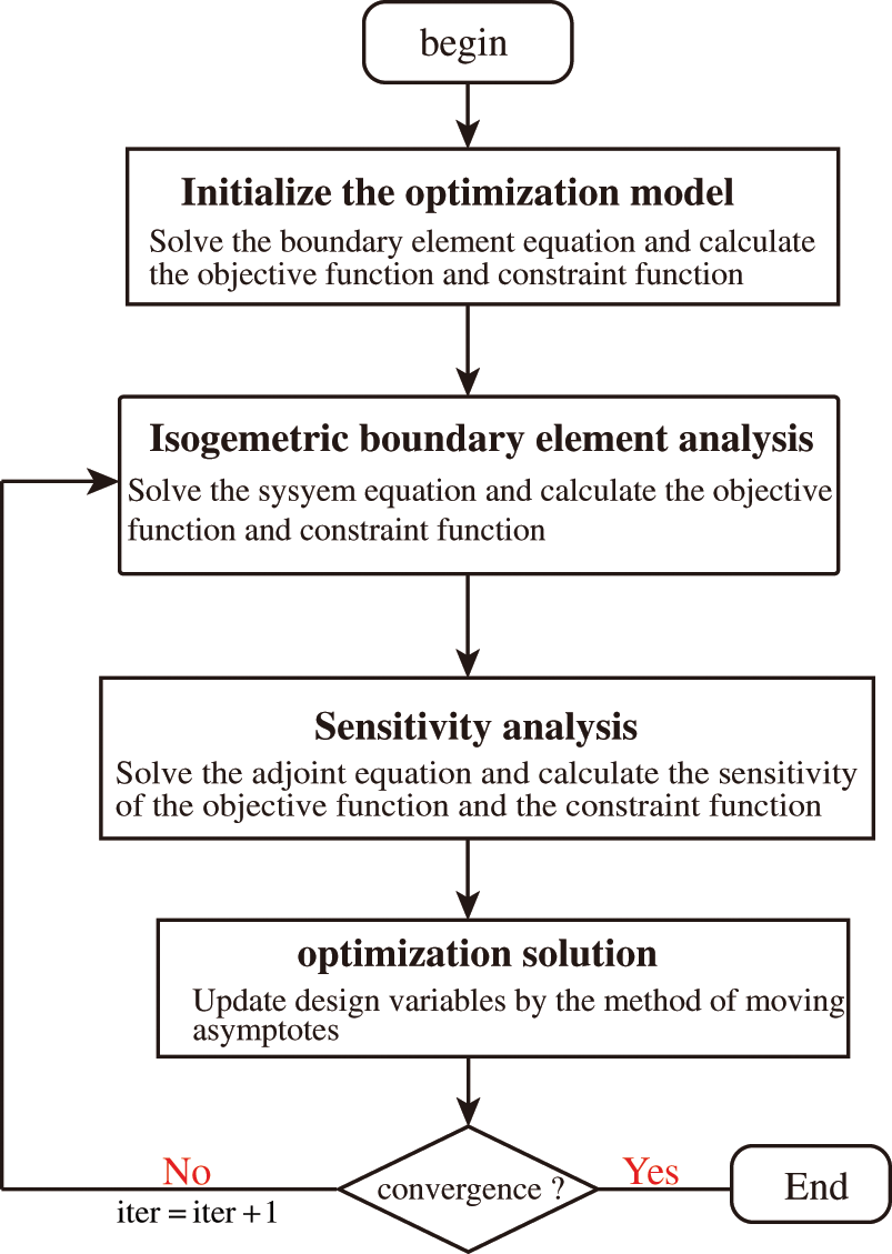
Figure 1: The flowchart of topology optimization process based on acoustic IGABEM
To investigate the effectiveness and applicability of the proposed optimization method, this section presents some numerical examples. In all examples, the boundary integral equations are discretized with the constant element. In addition, this work implements the topology optimization algorithm using Fortran 95 code. To improve computational efficiency, the OpenMP technique is employed to parallelization. The following analysis of the acoustic problems is performed on a desktop computer with an Intel Core i5-10400 CPU and 8 GB RAM. In this work, the number of Gaussian quadrature points utilized for regular integrals is
5.1 Half-Y Shaped Sound Barrier
In this work, we consider a computational domain of the half-Y shaped sound barrier as shown in Fig. 2. The width of the sound barrier is
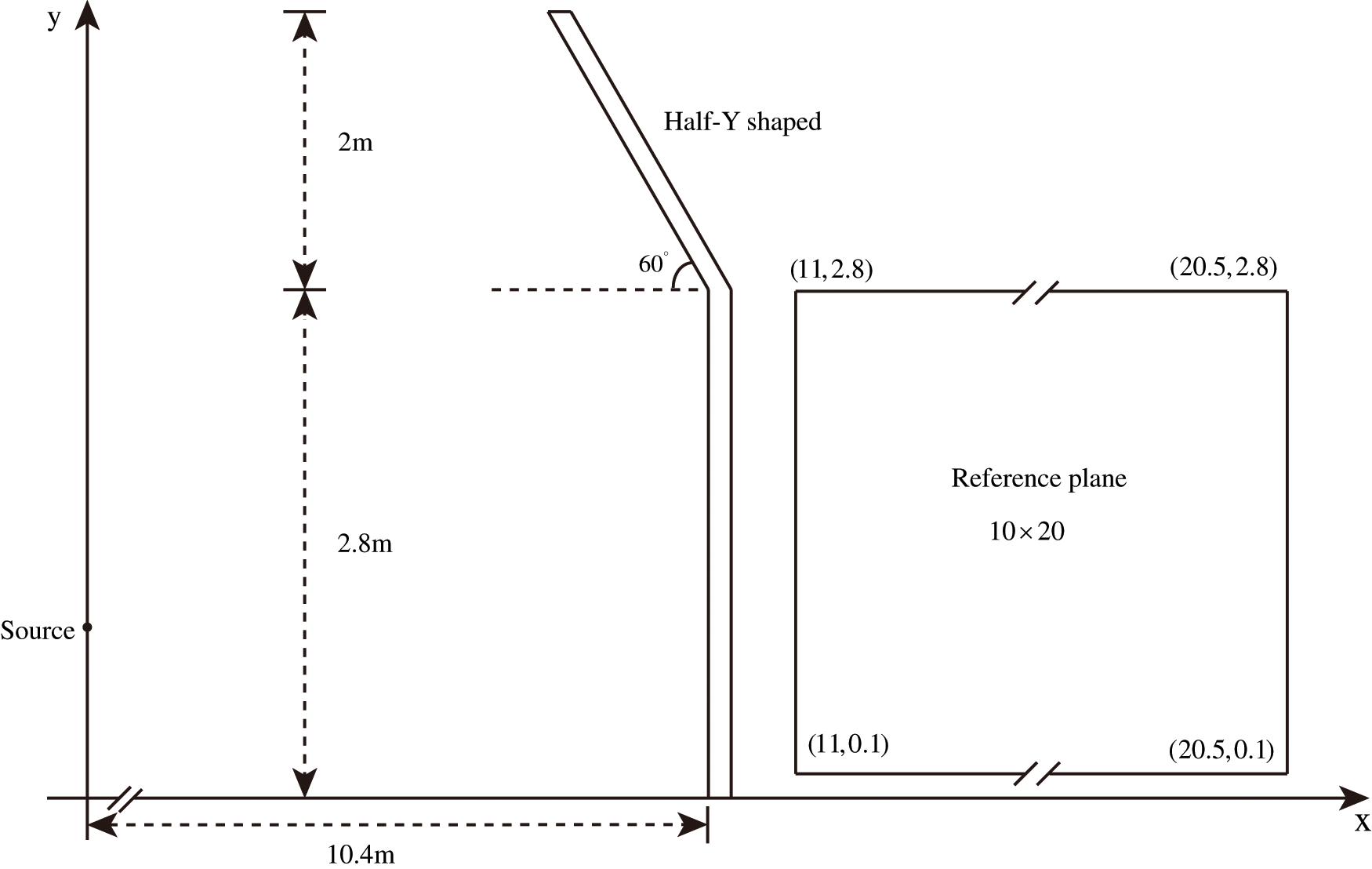
Figure 2: The computational domain of the half-Y shaped sound barrier and reference plane

Firstly, the topology optimization analysis is performed with MMA to verify its effectiveness. The initial values of design variables are set to 0.5, the volume ratio of sound-absorbing materials is bound to 1 and the penalization factor
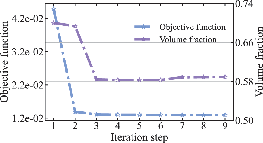
Figure 3: Objective function and volume fraction of half-Y shaped sound barrier at 70 Hz
It can be seen from Fig. 3 that the volume constraint changes very smoothly at the optimal solution. To examine in detail the reasons for the appearance of this phenomenon, the values of the sensitivity of all elements are given in Fig. 4 for the initial value, iteration step =
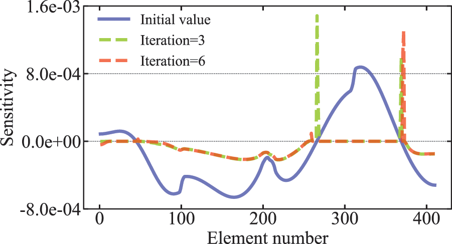
Figure 4: Distribution of the sensitivity value in the optimization process
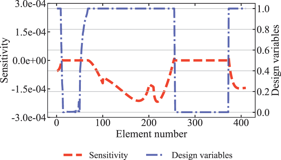
Figure 5: Distribution of design variables and sensitivity values after optimization convergence
Fig. 6 shows the optimal distribution of sound-absorbing materials on the surface of the sound barrier for different iteration steps during the optimization process, including the optimization iteration step =
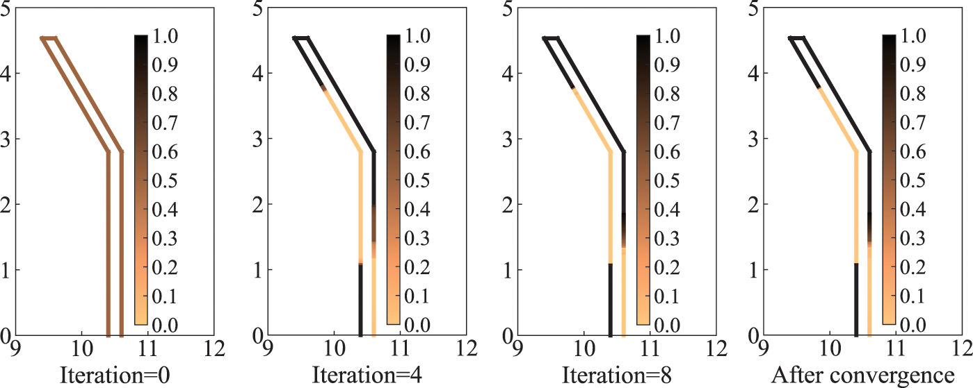
Figure 6: Distribution of sound-absorbing materials on the surface of half-Y shaped sound barrier under different iteration steps
As the optimization algorithm that we use iteratively updates the design variables with the help of the first-order gradient values of the objective function
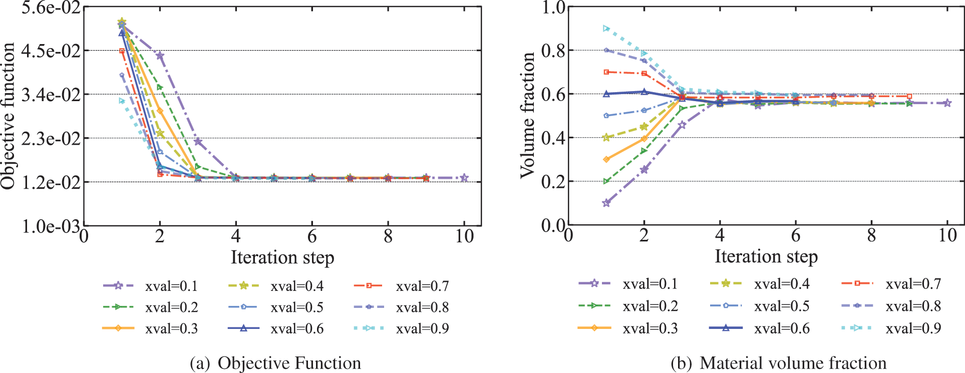
Figure 7: Objective functions and material volume fractions of sound barrier volumes for different initial values at 70 Hz
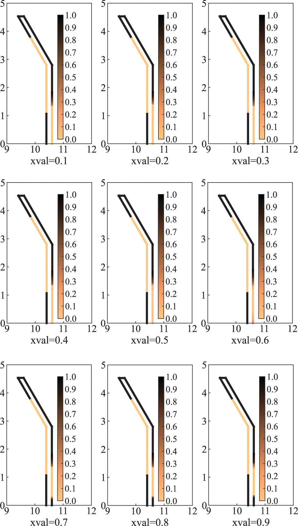
Figure 8: Optimized distribution of sound-absorbing materials for different initial design variables
As can be seen from Fig. 7b that the volume fraction of the final optimized distribution obtained by using a relatively high initial value is correspondingly higher. As can be seen from Fig. 8 when the initial values are chosen between 0.7 and 0.9, the final optimized distribution is very similar and the corresponding volume fractions in Fig. 7b are very close to 0.6. However, when the initial values were taken from 0.1 to 0.6, the optimized distribution was missing a piece in the lower right of the sound barrier compared to other optimized distributions. The volume fraction is between 0.5 and 0.6, and the corresponding objective function values are a little higher than other objective function values. It means that if the initial value is too small, it is possible to converge to the extreme value where the volume fraction is too small, and the original purpose of optimization cannot be achieved. In general, it is recommended to choose a relatively large initial design variable. In addition, we find that the optimized distribution obtained when the initial value is 0.9 is the highest volume fraction. However, there is no advantage over the optimized distribution of the initial values of 0.7 and 0.8. Therefore, different initial values lead to different optimization results.
To investigate the effect of frequency on the optimized distribution, we calculate the optimized distribution of sound-absorbing materials on the surface of the sound barrier at 70, 140 and 210 Hz, as shown in Fig. 9. As can be observed in the figure, the optimized distribution of sound-absorbing materials obtained at three different frequencies is different. This suggests that the optimized distribution is frequency-dependent and varies as frequency increases. As the frequency rises, the wavelength becomes shorter and the phase change period on the surface of the sound barrier becomes shorter. The interference of scattered and incident waves will be more dramatic between the two states of phase length and phase extinction interference, thereby the aggregated blocks of sound-absorbing materials on the surface of the sound barrier will become shorter and periodically distributed.
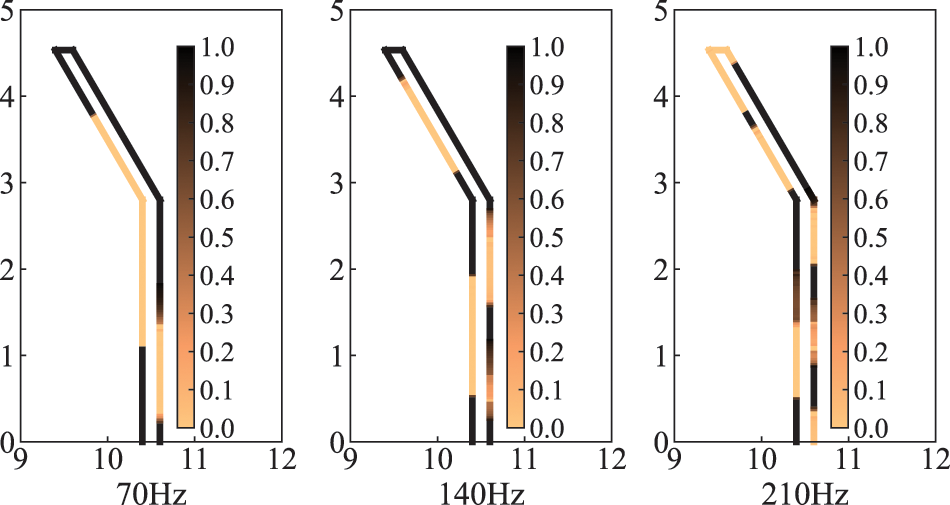
Figure 9: Optimized distribution of sound-absorbing materials for different frequencies
Since the optimized distribution is frequency-dependent, an optimized distribution at one frequency point may simply be better or even worse at other frequencies. And the actual noise usually contains components of different frequencies and intensities. Therefore, it is of engineering significance to consider the objective function in a frequency band range. The new objective function can be defined as Eq. (27)
where
The optimized distributions of sound-absorbing materials are given in Fig. 10 for three different frequency bands, including
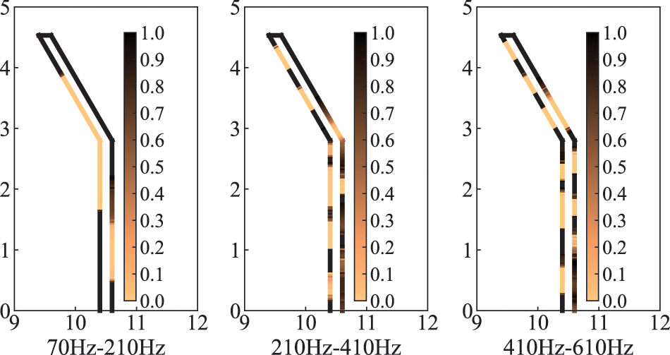
Figure 10: Optimized distribution of sound-absorbing materials in different frequency bands
In this section, to further detect the feasibility and effectiveness of the proposed topology optimization algorithm for different acoustic problems, a numerical analysis of a computational domain consisting of a plane incident wave and an infinite cylinder is carried out. This can be simplified to a two-dimensional problem, as shown in Fig. 11. The circle is discretized using 4,000 elements, thereby, the total degrees of freedom (DOF) is 4,000. Relevant physical parameters as shown in Table 2 and the volume constraint
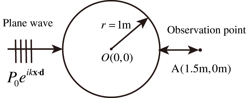
Figure 11: Computational domain of the optimization problem

Subsequently, we consider the optimization problem under the action of a plane wave

Figure 12: Objective function and volume fraction of the circle at 400 Hz
The optimized distributions of sound-absorbing materials after convergence are represented in Fig. 13. The optimization results for objective function 1 are shown in Figs. 13a and 13b shows the optimization results for objective function 2. The shade of color in the figure represents the relative magnitude of the design variable, where dark color indicates that the design variable is 1 and light color indicates that the design variable is 0. From the figure, it can be found that the optimized distribution obtained by the two different objective functions is completely different. The purpose of the optimal distribution of sound-absorbing materials is to find the optimal impedance boundary conditions so that the incident and scattering waves achieve the optimal interference in the sense of optimizing the target. When different objective functions are chosen, the corresponding optimal interference is often different. Therefore, the final optimized results are usually different as well. It can be observed from Fig. 13b that the vast majority of sound-absorbing materials are distributed in the left half-circle. This is mainly because the plane wave is located on the left side of the circle, so the sound pressure value on the left half-circle is higher than that on the right half circle. At this time, the sound-absorbing materials are organized in the left half-circle to absorb energy more efficiently. In addition, as the optimized area, the excitation and the examination point
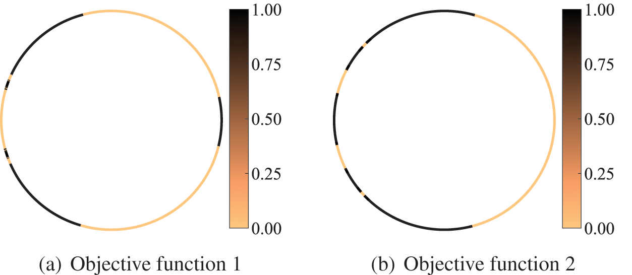
Figure 13: Material topology optimization distribution of the circle at 400 Hz
The sound field distribution on the boundary and in the region of an infinite cylinder is shown in Figs. 14 and 15, respectively. The selection of the observation point is consistent with the location of the observation point in Fig. 11, and the remaining parameters are the same as those in Table 2. We consider several different frequencies of the incident plane wave, including f = 100, 150, 200, 250, 300, 350, 400, 450, 500, 600, 650, 700, 800 and 900 Hz. It can be seen from the figure that the distribution of the sound pressure of porous materials is highly frequency-dependent, and its spatial distribution becomes more complex with the increase of incident frequency. In addition, the range of maximum and minimum sound pressure is not consistent for different objective functions. The sound field distribution on the boundary and in the region of an infinite cylinder is symmetric concerning the x axis. Subsequently, we similarly considered the topologically optimized distribution of sound-absorbing materials for different frequencies, as shown in Fig. 16. It can be seen from the figure that the distribution is different for different frequency points, which is consistent with the previously observed frequency-dependent. Although there are differences in the optimized distribution obtained at different frequency points, the basic distribution is very similar. Most porous materials are distributed in the left half-circle, as shown in Fig. 16b. Fig. 16 shows that the optimized distribution of the porous material is symmetric about the x axis.
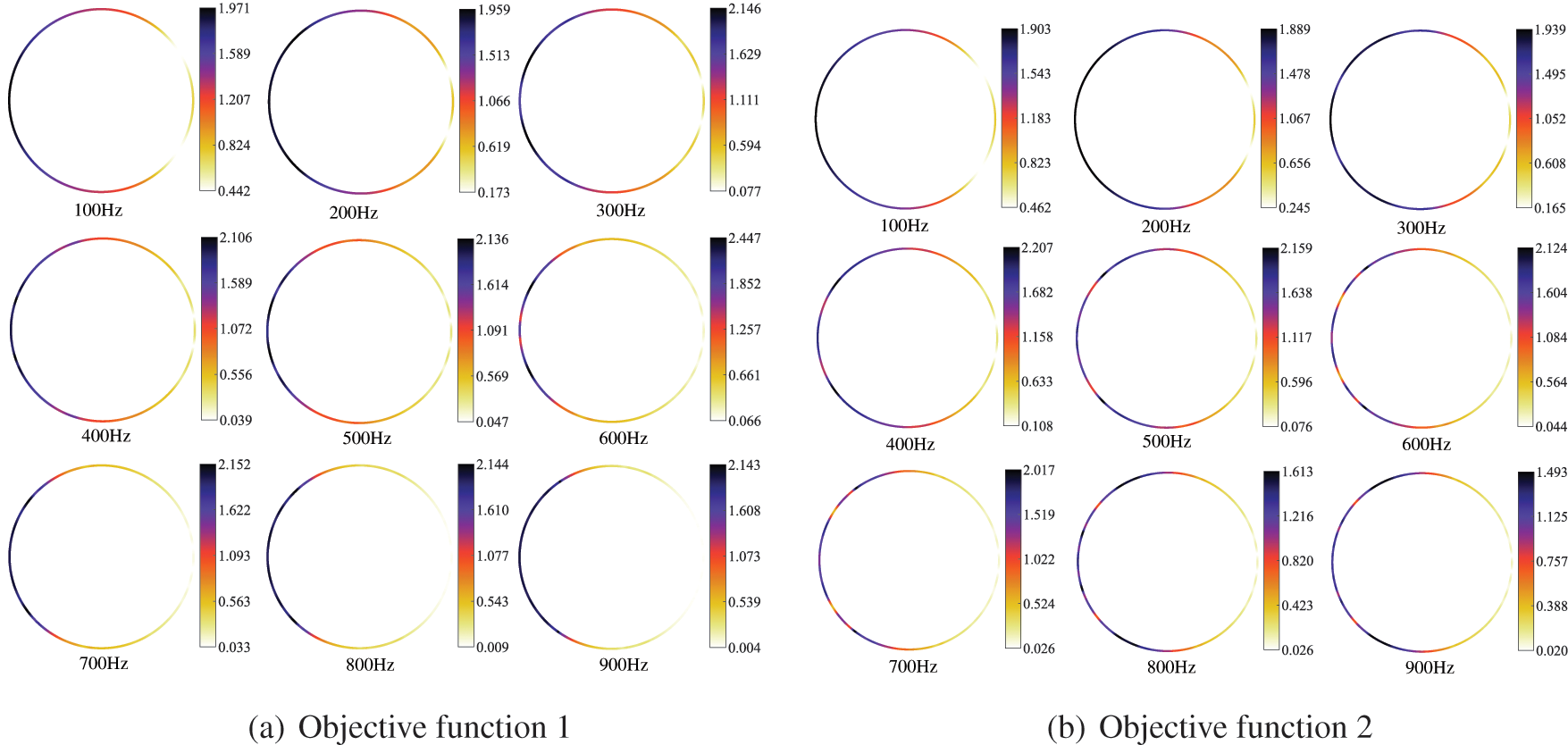
Figure 14: Distribution of the sound pressure for different frequencies
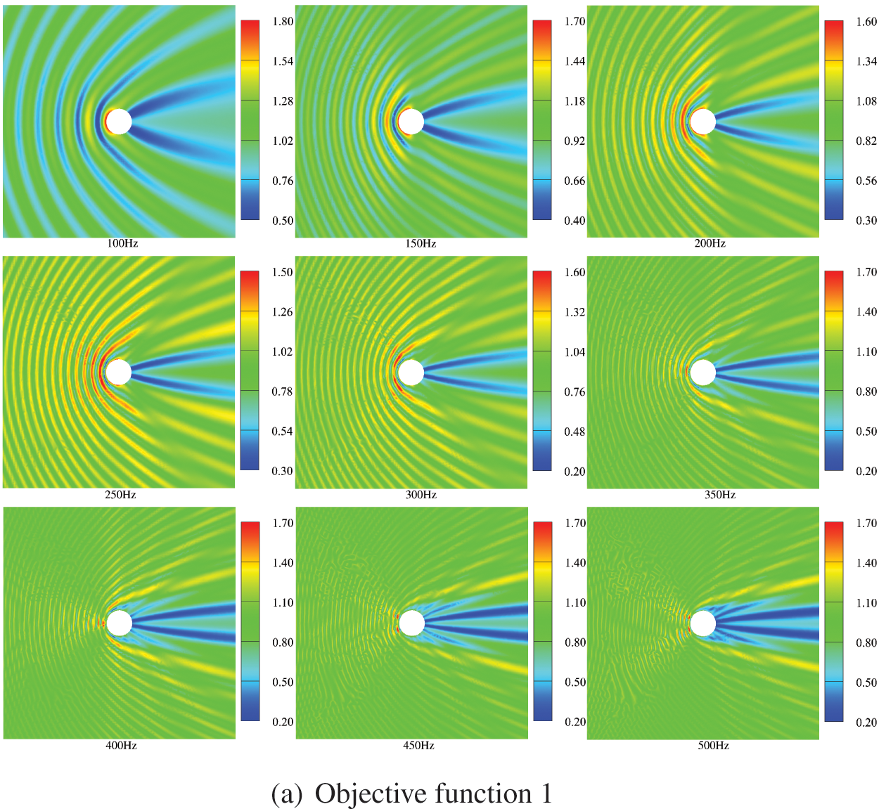
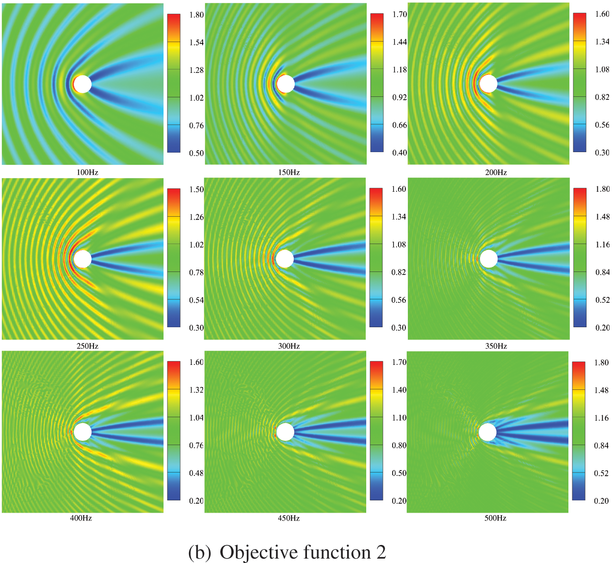
Figure 15: Optimized distribution of the sound pressure in the external sound field at different frequencies
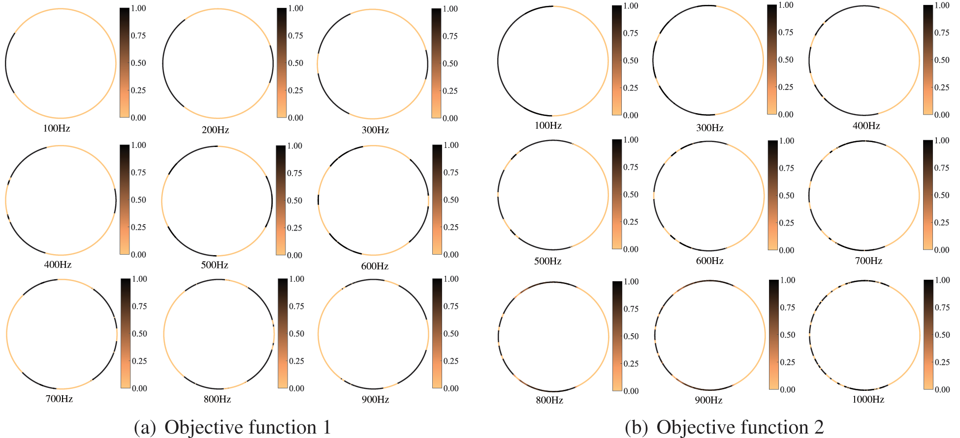
Figure 16: Material topology optimization distribution of the circle for different frequencies
In this work, the influence of the location of the observation point on the optimization result is investigated, and only objective function 1 is affected by the observation point. First, we consider six different observation points, as shown in Fig. 17. The computational frequency and other parameters are kept the same as before. Fig. 18 shows the optimized distribution of porous materials obtained by six different observation points when objective function 1 is selected. The optimized distribution of the six different observation points is significantly different, which indicates that the optimized distribution of sound-absorbing materials is very sensitive to the location of the selected observation point. The sound pressure at the observation point is determined by the interference between the incident and scattered waves, which in turn is influenced by the phase of the incident and scattered waves. Therefore, when the position of the observation point changes, the sound propagation path changes accordingly, which further results in a phase change. The final porous material needs to be adjusted according to the phase, etc., thus the optimized distribution depends on the chosen observation point. In addition, it can be observed that five observation points deviate from the x axis, so the corresponding optimized distribution is no longer symmetric about the x axis.
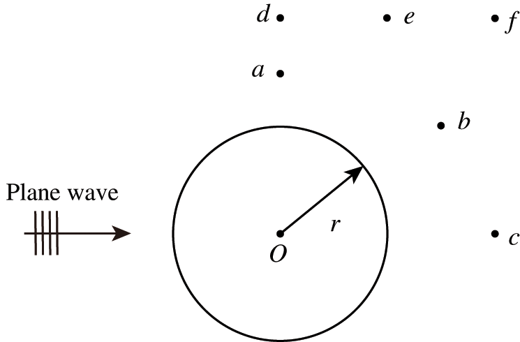
Figure 17: A model of the circle for different observation points
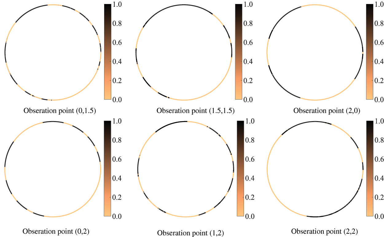
Figure 18: Optimized distribution of porous materials for different observation points
This work establishes a topology optimization method for porous sound-absorbing materials based on the acoustic IGABEM. The effectiveness of the algorithm is verified by numerical examples and the influence of frequency and location of the observation point on the optimization results is discussed. By analyzing results of different studies, we can draw some conclusions as follows:
1. The optimal distribution of the sound-absorbing material usually depends on the objective function chosen, so the optimized distribution is usually different for different objective functions.
2. Since the optimization distribution is frequency-dependent and location-dependent of the observation point, the optimization under the frequency band and the selection of multiple points or certain areas for investigation become more necessary and more engineering.
Acknowledgement: Thanks the editors of this journal and the anonymous reviewer.
Funding Statement: This work is sponsored by Natural Science Foundation of Henan under Grant No. 222300420498.
Conflicts of Interest: The authors declare that they have no conflicts of interest to report regarding the present study.
References
1. Kim, K. H., Yoon, G. H. (2015). Optimal rigid and porous material distributions for noise barrier by acoustic topology optimization. Journal of Sound and Vibration, 339, 123–142. DOI 10.1016/j.jsv.2014.11.030. [Google Scholar] [CrossRef]
2. Liu, C., Chen, L., Zhao, W., Chen, H. (2017). Shape optimization of sound barrier using an isogeometric fast multipole boundary element method in two dimensions. Engineering Analysis with Boundary Elements, 85, 142–157. DOI 10.1016/j.enganabound.2017.09.009. [Google Scholar] [CrossRef]
3. Jiang, F., Zhao, W., Chen, L., Zheng, C., Chen, H. (2021). Combined shape and topology optimization for sound barrier by using the isogeometric boundary element method. Engineering Analysis with Boundary Elements, 124, 124–136. DOI 10.1016/j.enganabound.2020.12.009. [Google Scholar] [CrossRef]
4. Nishio, S., Igarashi, M. (1990). Investigation of car body structural optimization method. International Journal of Vehicle Design, 11(1), 79–86. DOI 10.1504/IJVD.1990.061609. [Google Scholar] [CrossRef]
5. Marklund, P. O., Nilsson, L. (2001). Optimization of a car body component subjected to side impact. Structural and Multidisciplinary Optimization, 21(5), 383–392. DOI 10.1007/s001580100117. [Google Scholar] [CrossRef]
6. Li, C., Kim, I. Y. (2015). Topology, size and shape optimization of an automotive cross car beam. Proceedings of the Institution of Mechanical Engineers, Part D: Journal of Automobile Engineering, 229(10), 1361–1378. DOI 10.1177/0954407014561279. [Google Scholar] [CrossRef]
7. Dühring, M. B., Jensen, J. S., Sigmund, O. (2008). Acoustic design by topology optimization. Journal of Sound and Vibration, 317(3), 557–575. DOI 10.1016/j.jsv.2008.03.042. [Google Scholar] [CrossRef]
8. Bobby, S., Spence, S. M., Bernardini, E., Kareem, A. (2014). Performance–based topology optimization for wind–excited tall buildings: A framework. Engineering Structures, 74, 242–255. DOI 10.1016/j.engstruct.2014.05.043. [Google Scholar] [CrossRef]
9. Oh, S., Wang, S., Cho, S. (2016). Topology optimization of a suction muffler in a fluid machine to maximize energy efficiency and minimize broadband noise. Journal of Sound and Vibration, 366, 27–43. DOI 10.1016/j.jsv.2015.10.022. [Google Scholar] [CrossRef]
10. Azevedo, F. M., Moura, M. S., Vicente, W. M., Picelli, R., Pavanello, R. (2018). Topology optimization of reactive acoustic mufflers using a bi-directional evolutionary optimization method. Structural and Multidisciplinary Optimization, 58(5), 2239–2252. DOI 10.1007/s00158-018-2012-5. [Google Scholar] [CrossRef]
11. Sakagami, K., Uyama, T., Kiyama, M., Morimoto, M. (1998). Absorption characteristics of a double–leaf membrane with an absorptive layer in its cavity. The Journal of the Acoustical Society of America, 103(5), 3065–3065. DOI 10.1121/1.422830. [Google Scholar] [CrossRef]
12. Ishizuka, T., Fujiwara, K. (2004). Performance of noise barriers with various edge shapes and acoustical conditions. Applied Acoustics, 65(2), 125–141. DOI 10.1016/j.apacoust.2003.08.006. [Google Scholar] [CrossRef]
13. Cao, L., Fu, Q., Si, Y., Ding, B., Yu, J. (2018). Porous materials for sound absorption. Composites Communications, 10, 25–35. DOI 10.1016/j.coco.2018.05.001. [Google Scholar] [CrossRef]
14. Chen, L., Liu, C., Zhao, W., Liu, L. (2018). An isogeometric approach of two dimensional acoustic design sensitivity analysis and topology optimization analysis for absorbing material distribution. Computer Methods in Applied Mechanics and Engineering, 336, 507–532. DOI 10.1016/j.cma.2018.03.025. [Google Scholar] [CrossRef]
15. Chen, L., Lian, H., Liu, Z., Gong, Y., Zheng, C. et al. (2022). Bi-material topology optimization for fully coupled structural–acoustic systems with isogeometric FEM–BEM. Engineering Analysis with Boundary Elements, 135, 182–195. DOI 10.1016/j.enganabound.2021.11.005. [Google Scholar] [CrossRef]
16. Bruns, T. E., Tortorelli, D. A. (2001). Topology optimization of non-linear elastic structures and compliant mechanisms. Computer Methods in Applied Mechanics and Engineering, 190(26), 3443–3459. DOI 10.1016/S0045-7825(00)00278-4. [Google Scholar] [CrossRef]
17. Takezawa, A., Yoon, G. H., Jeong, S. H., Kobashi, M., Kitamura, M. (2014). Structural topology optimization with strength and heat conduction constraints. Computer Methods in Applied Mechanics and Engineering, 276, 341–361. DOI 10.1016/j.cma.2014.04.003. [Google Scholar] [CrossRef]
18. Russ, J. B., Waisman, H. (2019). Topology optimization for brittle fracture resistance. Computer Methods in Applied Mechanics and Engineering, 347, 238–263. DOI 10.1016/j.cma.2018.12.031. [Google Scholar] [CrossRef]
19. Bendsøe, M. P., Kikuchi, N. (1988). Generating optimal topologies in structural design using a homogenization method. Computer Methods in Applied Mechanics and Engineering, 71(2), 197–224. DOI 10.1016/0045-7825(88)90086-2. [Google Scholar] [CrossRef]
20. Lee, J., Wang, S., Dikec, A. (2004). Topology optimization for the radiation and scattering of sound from thin-body using genetic algorithms. Journal of Sound and Vibration, 276(3), 899–918. DOI 10.1016/j.jsv.2003.08.009. [Google Scholar] [CrossRef]
21. Du, J., Olhoff, N. (2007). Minimization of sound radiation from vibrating bi–material structures using topology optimization. Structural and Multidisciplinary Optimization, 33(4), 305–321. DOI 10.1007/s00158-006-0088-9. [Google Scholar] [CrossRef]
22. Yoon, G. H. (2013). Acoustic topology optimization of fibrous material with delany–bazley empirical material formulation. Journal of Sound and Vibration, 332(5), 1172–1187. DOI 10.1016/j.jsv.2012.10.018. [Google Scholar] [CrossRef]
23. Chen, L., Lian, H., Liu, Z., Chen, H., Atroshchenko, E. et al. (2019). Structural shape optimization of three dimensional acoustic problems with isogeometric boundary element methods. Computer Methods in Applied Mechanics and Engineering, 355, 926–951. DOI 10.1016/j.cma.2019.06.012. [Google Scholar] [CrossRef]
24. Yoon, G. H., Jensen, J. S., Sigmund, O. (2007). Topology optimization of acoustic–structure interaction problems using a mixed finite element formulation. International Journal for Numerical Methods in Engineering, 70(9), 1049–1075. DOI 10.1002/(ISSN)1097-0207. [Google Scholar] [CrossRef]
25. Meric, R. (1995). Differential and integral sensitivity formulations and shape optimization by BEM. Engineering Analysis with Boundary Elements, 15(2), 181–188. DOI 10.1016/0955-7997(95)00016-H. [Google Scholar] [CrossRef]
26. Tinnsten, M., Esping, B., Jonsson, M. (1999). Optimization of acoustic response. Structural Optimization, 18(1), 36–47. DOI 10.1007/BF01210690. [Google Scholar] [CrossRef]
27. Baulac, M., Defrance, J., Jean, P. (2007). Optimization of multiple edge barriers with genetic algorithms coupled with a nelder–mead local search. Journal of Sound and Vibration, 300(1), 71–87. DOI 10.1016/j.jsv.2006.07.030. [Google Scholar] [CrossRef]
28. Chen, L., Wang, Z., Peng, X., Yang, J., Wu, P. et al. (2021). Modeling pressurized fracture propagation with the isogeometric BEM. Geomechanics and Geophysics for Geo-Energy and Geo-Resources, 7(3), 51. DOI 10.1007/s40948-021-00248-3. [Google Scholar] [CrossRef]
29. Peng, X., Lian, H., Ma, Z., Zheng, C. (2022). Intrinsic extended isogeometric analysis with emphasis on capturing high gradients or singularities. Engineering Analysis with Boundary Elements, 134, 231–240. DOI 10.1016/j.enganabound.2021.09.022. [Google Scholar] [CrossRef]
30. Chen, L., Marburg, S., Zhao, W., Liu, C., Chen, H. (2019). Implementation of isogeometric fast multipole boundary element methods for 2D half-space acoustic scattering problems with absorbing boundary condition. Journal of Theoretical and Computational Acoustics, 27(2), 1850024. DOI 10.1142/S259172851850024X. [Google Scholar] [CrossRef]
31. Hughes, T., Cottrell, J., Bazilevs, Y. (2005). Isogeometric analysis: CAD, finite elements, NURBS, exact geometry and mesh refinement. Computer Methods in Applied Mechanics and Engineering, 194(39), 4135–4195. DOI 10.1016/j.cma.2004.10.008. [Google Scholar] [CrossRef]
32. Chen, L., Lu, C., Zhao, W., Chen, H., Zheng, C. (2020). Subdivision surfaces-boundary element accelerated by fast multipole for the structural acoustic problem. Journal of Theoretical and Computational Acoustics, 28(2), 2050011. DOI 10.1142/S2591728520500115. [Google Scholar] [CrossRef]
33. Ginnis, A., Kostas, K., Politis, C., Kaklis, P., Belibassakis, K. et al. (2014). Isogeometric boundary-element analysis for the wave-resistance problem using T-splines. Computer Methods in Applied Mechanics and Engineering, 279, 425–439. DOI 10.1016/j.cma.2014.07.001. [Google Scholar] [CrossRef]
34. Peake, M., Trevelyan, J., Coates, G. (2015). Extended isogeometric boundary element method (XIBEM) for three-dimensional medium-wave acoustic scattering problems. Computer Methods in Applied Mechanics and Engineering, 284, 762–780. DOI 10.1016/j.cma.2014.10.039. [Google Scholar] [CrossRef]
35. Sun, Y., Trevelyan, J., Hattori, G., Lu, C. (2019). Discontinuous isogeometric boundary element (IGABEM) formulations in 3D automotive acoustics. Engineering Analysis with Boundary Elements, 105, 303–311. DOI 10.1016/j.enganabound.2019.04.011. [Google Scholar] [CrossRef]
36. Simpson, R., Scott, M., Taus, M., Thomas, D., Lian, H. (2014). Acoustic isogeometric boundary element analysis. Computer Methods in Applied Mechanics and Engineering, 269, 265–290. DOI 10.1016/j.cma.2013.10.026. [Google Scholar] [CrossRef]
37. Shaaban, A. M., Anitescu, C., Atroshchenko, E., Rabczuk, T. (2021). 3D isogeometric boundary element analysis and structural shape optimization for helmholtz acoustic scattering problems. Computer Methods in Applied Mechanics and Engineering, 384, 113950. DOI 10.1016/j.cma.2021.113950. [Google Scholar] [CrossRef]
38. Chen, L., Zhang, Y., Lian, H., Atroshchenko, E., Ding, C. et al. (2020). Seamless integration of computer-aided geometric modeling and acoustic simulation: Isogeometric boundary element methods based on catmull-clark subdivision surfaces. Advances in Engineering Software, 149, 102879. DOI 10.1016/j.advengsoft.2020.102879. [Google Scholar] [CrossRef]
39. Chen, L., Cheng, R., Li, S., Lian, H., Zheng, C. et al. (2022). A sample-efficient deep learning method for multivariate uncertainty qualification of acoustic-vibration interaction problems. Computer Methods in Applied Mechanics and Engineering, 393, 114784. DOI 10.1016/j.cma.2022.114784. [Google Scholar] [CrossRef]
40. Lamancusa, J. (1993). Numerical optimization techniques for structural–acoustic design of rectangular panels. Computers & Structures, 48(4), 661–675. DOI 10.1016/0045-7949(93)90260-K. [Google Scholar] [CrossRef]
41. Chen, L., Marburg, S., Chen, H., Zhang, H., Gao, H. (2017). An adjoint operator approach for sensitivity analysis of radiated sound power in fully coupled structural-acoustic systems. Journal of Computational Acoustics, 25(1), 1750003. DOI 10.1142/S0218396X17500035. [Google Scholar] [CrossRef]
42. Zhao, W., Chen, L., Chen, H., Marburg, S. (2019). Topology optimization of exterior acoustic-structure interaction systems using the coupled FEM–BEM method. International Journal for Numerical Methods in Engineering, 119(5), 404–431. DOI 10.1002/nme.6055. [Google Scholar] [CrossRef]
43. Fritze, D., Marburg, S., Hardtke, H. J. (2005). FEM–BEM–coupling and structural–acoustic sensitivity analysis for shell geometries. Computers & Structures, 83(2), 143–154. DOI 10.1016/j.compstruc.2004.05.019. [Google Scholar] [CrossRef]
44. Matsumoto, T., Tanaka, M., Yamada, Y. (1995). Design sensitivity analysis of steady–state acoustic problems using boundary integral equation formulation. JSME international journal. Ser. C, Dynamics, control, robotics, design and manufacturing, 38(1), 9–16. DOI 10.1299/jsmec1993.38.9. [Google Scholar] [CrossRef]
45. Zheng, C., Matsumoto, T., Takahashi, T., Chen, H. (2012). A wideband fast multipole boundary element method for three dimensional acoustic shape sensitivity analysis based on direct differentiation method. Engineering Analysis with Boundary Elements, 36(3), 361–371. DOI 10.1016/j.enganabound.2011.09.001. [Google Scholar] [CrossRef]
46. Denli, H., Sun, J. (2008). Structural–acoustic optimization of sandwich cylindrical shells for minimum interior sound transmission. Journal of Sound and Vibration, 316(1), 32–49. DOI 10.1016/j.jsv.2008.02.027. [Google Scholar] [CrossRef]
47. Chen, L., Chen, H., Zheng, C., Marburg, S. (2016). Structural–acoustic sensitivity analysis of radiated sound power using a finite element/discontinuous fast multipole boundary element scheme. International Journal for Numerical Methods in Fluids, 82(12), 858–878. DOI 10.1002/fld.4244. [Google Scholar] [CrossRef]
48. Troian, R., Gillot, F., Besset, S. (2015). Adjoint sensitivity related to geometric parameters for mid–high frequency range vibroacoustics. Structural and Multidisciplinary Optimization, 52(4), 803–811. DOI 10.1007/s00158-015-1270-8. [Google Scholar] [CrossRef]
49. Isakari, H., Kondo, T., Takahashi, T., Matsumoto, T. (2017). A level–set–based topology optimisation for acoustic–elastic coupled problems with a fast BEM–FEM solver. Computer Methods in Applied Mechanics and Engineering, 315, 501–521. DOI 10.1016/j.cma.2016.11.006. [Google Scholar] [CrossRef]
50. Koo, K., Pluymers, B., Desmet, W., Wang, S. (2011). Vibro–acoustic design sensitivity analysis using the wave–based method. Journal of Sound and Vibration, 330(17), 4340–4351. DOI 10.1016/j.jsv.2011.03.030. [Google Scholar] [CrossRef]
51. Zuo, W., Saitou, K. (2017). Multi-material topology optimization using ordered simp interpolation. Structural and Multidisciplinary Optimization, 55(2), 477–491. DOI 10.1007/s00158-016-1513-3. [Google Scholar] [CrossRef]
52. Noguchi, Y., Yamamoto, T., Yamada, T., Izui, K., Nishiwaki, S. (2017). A level set–based topology optimization method for simultaneous design of elastic structure and coupled acoustic cavity using a two–phase material model. Journal of Sound and Vibration, 404, 15–30. DOI 10.1016/j.jsv.2017.05.040. [Google Scholar] [CrossRef]
53. Hu, J., Yao, S., Huang, X. (2020). Topology optimization of dynamic acoustic–mechanical structures using the ersatz material model. Computer Methods in Applied Mechanics and Engineering, 372, 113387. DOI 10.1016/j.cma.2020.113387. [Google Scholar] [CrossRef]
54. Bendsøe, M. P., Sigmund, O. (1999). Material interpolation schemes in topology optimization. Archive of Applied Mechanics, 69(9), 635–654. DOI 10.1007/s004190050248. [Google Scholar] [CrossRef]
55. Bendsøe, M. P. (1989). Optimal shape design as a material distribution problem. Structural Optimization, 1(4), 193–202. DOI 10.1007/BF01650949. [Google Scholar] [CrossRef]
56. Li, J. C., Tu, W. T., Yang, X. D., Fu, J., Wang, Y. T. (2011). Heat conduction structural topology optimization based on RAMP. In: Applied mechanics and materials, vol. 52, pp. 1692–1697. Trans Tech Publications, Ltd. [Google Scholar]
57. Svanberg, K. (1987). The method of moving asymptotes–A new method for structural optimization. International Journal for Numerical Methods in Engineering, 24(2), 359–373. DOI 10.1002/(ISSN)1097-0207. [Google Scholar] [CrossRef]
58. Burton, A. J., Miller, G. F., Wilkinson, J. H. (1971). The application of integral equation methods to the numerical solution of some exterior boundary-value problems. Proceedings of the Royal Society A. Mathematical and Physical Sciences, 323(1553), 201–210. DOI 10.1098/rspa.1971.0097. [Google Scholar] [CrossRef]
Cite This Article
 Copyright © 2023 The Author(s). Published by Tech Science Press.
This work is licensed under a Creative Commons Attribution 4.0 International License , which permits unrestricted use, distribution, and reproduction in any medium, provided the original work is properly cited.


 Submit a Paper
 Propose a Special lssue
 View Full Text
 Download PDF
 Downloads
 Citation Tools