
 Submit a Paper
 Propose a Special lssue
 Open Access
ARTICLE
A Hybrid Regional Model for Predicting Ground Deformation Induced by Large-Section Tunnel Excavation
1
Institute of Geotechnical Engineering, Nanjing Tech University, Nanjing, 210009, China
2
Research Center of Coastal and Urban Geotechnical Engineering, Zhejiang University, Hangzhou, 310058, China
3
Department of Civil and Environmental Engineering, Princeton University, Princeton, 08544, USA
4
Key Laboratory of Geotechnical and Engineering of Ministry of Education, Department of Geotechnical Engineering,
Tongji University, Shanghai, 200092, China
* Corresponding Author: Shengjun Deng. Email:
(This article belongs to the Special Issue: Mechanical Reliability of Advanced Materials and Structures for Harsh Applications)
Computer Modeling in Engineering & Sciences 2023, 134(1), 495-516. https://doi.org/10.32604/cmes.2022.020386
Received 20 November 2021; Accepted 17 February 2022; Issue published 24 August 2022
 View Full Text
 Download PDF
Abstract
Due to the large number of finite element mesh generated, it is difficult to use full-scale model to simulate largesection underground engineering, especially considering the coupling effect. A regional model is attempted to achieve this simulation. A variable boundary condition method for hybrid regional model is proposed to realize the numerical simulation of large-section tunnel construction. Accordingly, the balance of initial ground stress under asymmetric boundary conditions achieves by applying boundary conditions step by step with secondary development of Dynaflow scripts, which is the key issue of variable boundary condition method implementation. In this paper, Gongbei tunnel based on hybrid regional model involving multi-field coupling is simulated. Meanwhile, the variable boundary condition method for regional model is verified against model initialization and the ground deformation due to tunnel excavation is predicted via the proposed hybrid regional model. Compared with the monitoring data of actual engineering, the results indicated that the hybrid regional model has a good prediction effect.Keywords
The ground surface deformation due to construction is one of the most concerning issues in shallow-buried underground excavation [1–4]. Finite element method is an effective method to explore the law. However, for large-section engineering, especially complex ones related to coupled moisture, heat and stress field, the computational efficiency is very low and the computational effort is large [5,6]. Due to the large size and complexity of the model, the mesh division is rough, thus the local details of the model may not be considered. It is difficult to ensure the precision of the concerned region. In consideration of computational effort and calculation precision for such large-scale model, a variable boundary condition method for hybrid regional model of underground engineering is proposed. As the size of the model is greatly reduced, the calculation efficiency and precision can be greatly improved, which makes some complex numerical simulation possible.
For the large-scale structure, there are two methods to deal with local regions. One is to refine the mesh of local region in the whole model, but only for the case where the whole model adopts the solid element and the shell element [7–9]. The other one is to extract the regional model in the overall model. In other words, the local finite element model is established separately and the meshing is refined. Then the corresponding boundary conditions and loads are applied to the truncated boundary of the whole model, and the finite element analysis is performed [10].
But for underground engineering, the model becomes more complicated because it involves the balance of initial ground stress [11]. This type of problem is achieved through large-scale model tests [12,13]. Therefore, there are few cases where underground engineering problems are solved through regional model. The difference between full-scale model and regional model is whether the boundary condition changes. Obviously, the boundary condition of regional model will change after the step of ground stress equilibration, which is the key issue. In this paper, Gongbei tunnel is taken as an example to simulate the regional model based on the script of a standard finite element package DynaflowTM [14].
This paper presents hybrid regional model to realize the numerical simulation of such large-section tunnel construction, which is the first attempt in underground engineering. Two input files are written through secondary development of Dynaflow script to implement the calculation of hybrid regional model. The proposed hybrid regional model can realize the balance of ground stress under asymmetry boundary condition. The verification of the model is made by initialization and comparing the computational results of the model with the monitoring data. The computing realization of hybrid regional model can serve as a reference for similar large-section underground engineering.
2 Concept of Hybrid Regional Model
Due to the ground stress equilibration involved, the core issue of using regional model to simulate an underground engineering case is the processing of boundary conditions. The simulation process is divided into two major stages, the balance of initial ground stress and the construction. As shown in Fig. 1, considering the symmetry of the model, the left half of the model is taken as a regional model. The model contains two parts of covering soil and the crown of the tunnel, where the crown part will be removed during excavation stage. In the stage of ground stress equilibration, the boundary conditions on the left and right sides are symmetrically distributed as shown in Fig. 1A. Once entering the construction stage, the boundary conditions on the left side will change, forming an asymmetrical state. Since the left side face is less constrained in vertical direction near the ground surface, other parts are restricted by more the surrounding soil, which can be approximated as complete constraints. Therefore, vertical constraint is added to the left boundary to simulate the constraints of the lateral soil, shown in Fig. 1B.
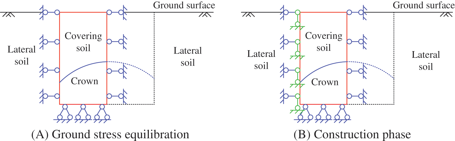
Figure 1: Boundary conditions of hybrid regional model at different phases
2.2 Model Strategy for Tunneling Simulation
Considering that the ground stress equilibration can only be carried out under symmetric boundary condition, in order to set up the boundary conditions under asymmetric condition, the process needs to be divided into two steps, corresponding to two input files, file A and file B.
The simulation is performed by the script of DynaflowTM, which is a finite element software. The preprocessing of hybrid regional model depends on Gmesh [15], which is a three-dimensional finite element grid generator with a build-in CAD engine and post-processor. Its design goal is to provide a fast, light and user-friendly meshing tool with parametric input and advanced visualization capabilities, while the post processing depends on FemGV [16], which is a general purpose pre-and post-processor for Finite Element Analysis (FEA) software. The calculation flow is shown in Fig. 2. As described above, the implementation of boundary condition is divided into two steps. Input file A is responsible for the calculation of the ground stress equilibration stage. The ground stress result of input file A is called by input file B as initial ground stress state of construction stage, which is not affected by the asymmetric boundary condition applied later. The above introduction is the main framework of regional model simulation. Finally, the implementation and verification of the hybrid regional model script will be reflected in the Gongbei tunnel case.
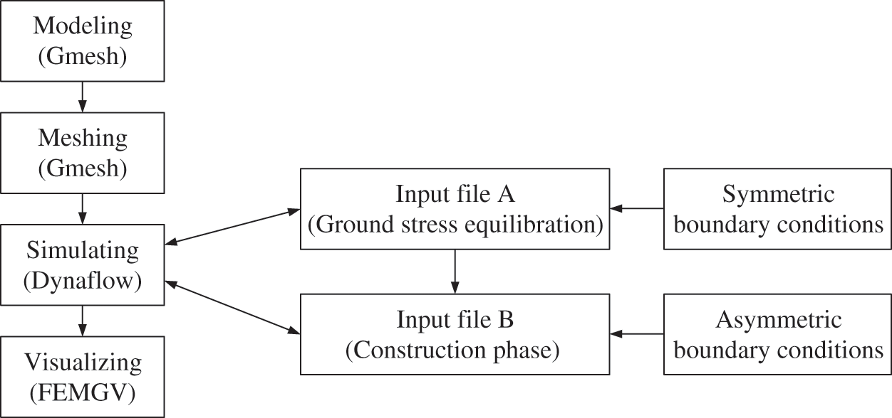
Figure 2: Calculation procedure
3 Application of Hybrid Regional Model in 3D Tunneling Simulation
3.1 Brief Description of Gongbei Tunnel
The Freeze-Sealing Pipe Roof (FSPR) method is applied to Gongbei tunnel that is a critical link of Hongkong-Zhuhai-Macau Bridge. Meanwhile, it is the first application in the world. The definition of FSPR method is that large diameter steel pipes are laid out in a circle around the cross section of tunnel in advance, and then the artificial ground freezing method is adopted to freeze soil between pipe roof to form waterproof curtain [17,18]. The freezing tubes that circulates low temperature brine installed inside the roofing pipes [19]. Fig. 3 shows the original design of the pipe roofing, which consists of 36 pieces of 1620 mm diameter roofing pipes around the circumference of excavation. The spacing between the pipe edges ranges between 35.5 and 35.8 cm. In the normal direction of the tunnel circumference, the odd number roof pipes are shifted by 30 cm to the tunnel direction with respect to the even diameter pipes. The excavation cross-sectional area is approximately 345 m2 with 18.8 m in width and 20.6 m in height, which is the largest single tunnel excavation in China. The tunnel is buried within soft sandy about 4.5 m below the ground surface at the Gongbei customer port.
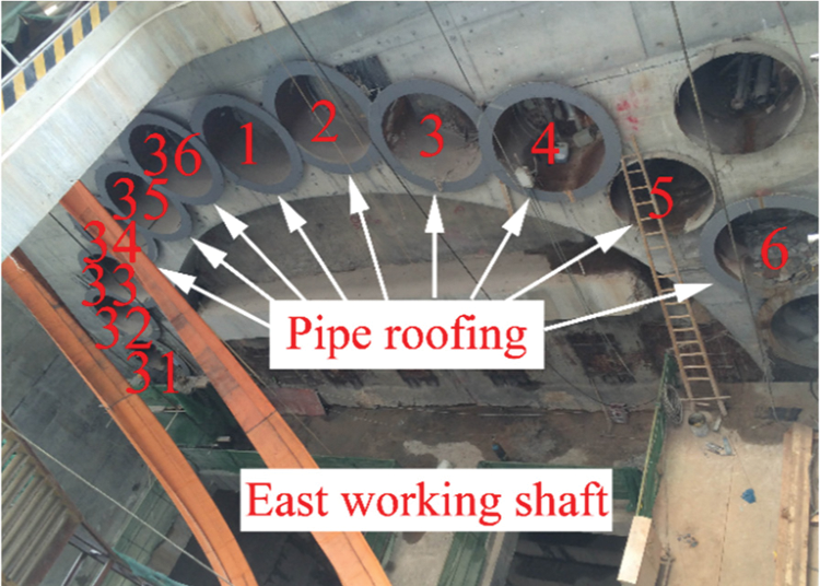
Figure 3: Layout of the pipe-roofing
Some scholars did research about the mechanical mechanism of steel pipes-frozen soil composite structure through laboratory test. A preliminary model test study of simplified composite structure with two pipes and three pipes was conducted, respectively [20–23]. Few scholars did research about combined pipe roof and frozen soil structure, especially with finite element method. The reason is that the model is too large and complex so that the computational efficiency is extremely low and the computational effort is large, which is also the issue to be solved in this paper.
There're three stages before excavation, pipe jacking, concrete filling and ground freezing. The roofing pipes are designed to be jacked section by section with a sectional length of 4 m from the construction shaft at one end of the tunnel alignment and received in the construction shaft at the other end of the tunnel alignment. To control the ground movement during pipe jacking, small tunnel boring machines (TBMs) are applied to tunnel through the ground, followed by the jacking of the pipe sections [24,25]. And then concrete will be filled into the odd pipes, which is good for heat conduction. After that, ground freezing will last 50 days before tunnel excavation and the thickness of frozen soil should be in control of 2∼2.6 m during construction. Supports and lining will be used during and after excavation. Concrete backfilling of even pipes and thawing process will be carried out after the completion of excavation.
In consideration of mesh scale effect and computational capability, the local part of the composite structure was chosen to simulate. Fig. 4A shows that local symmetry model is located at the top of the FSPR composite structure, including one hollow steel pipe and half of concrete-filled steel pipe. The geometry of hybrid regional model is shown in Fig. 4B. The distance between the top point of concrete-filled steel pipe and ground surface is 4.5 m. The diameter of the steel pipe is 1.62 m with 0.02 m thickness. The space between two pipes is 0.355 m.
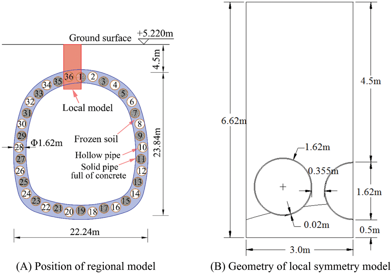
Figure 4: Local simulation model
According to the simplified model above, Fig. 5 is 3D mesh model of the hybrid regional model with 0.8 m thickness, which is the maximum excavation length for each step. 3D model can reflect the longitudinal force characteristics more than 2D, which is closer to the real working condition. There are 6 parts in the model, which is made up of soil, steel pipes, concrete. There are 5134 nodes and 31505 elements in total.
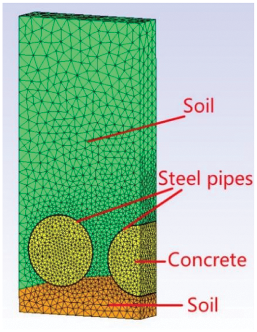
Figure 5: 3D mesh model
In actual construction, tunnel excavation starts from the top of the crown where the deformation is the largest. Fig. 6 shows the region of the hybrid regional model under the observation of inside view of the tunnel. It shows the soil excavation section and the lower half part of the steel pipe only. The upper half part of the model extending to the surface is hidden in the soil.
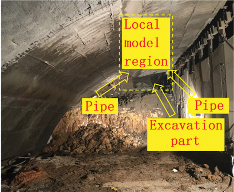
Figure 6: Hybrid regional model region of actual construction
The constraints of each face of actual project are shown in Fig. 7A. The upper surface
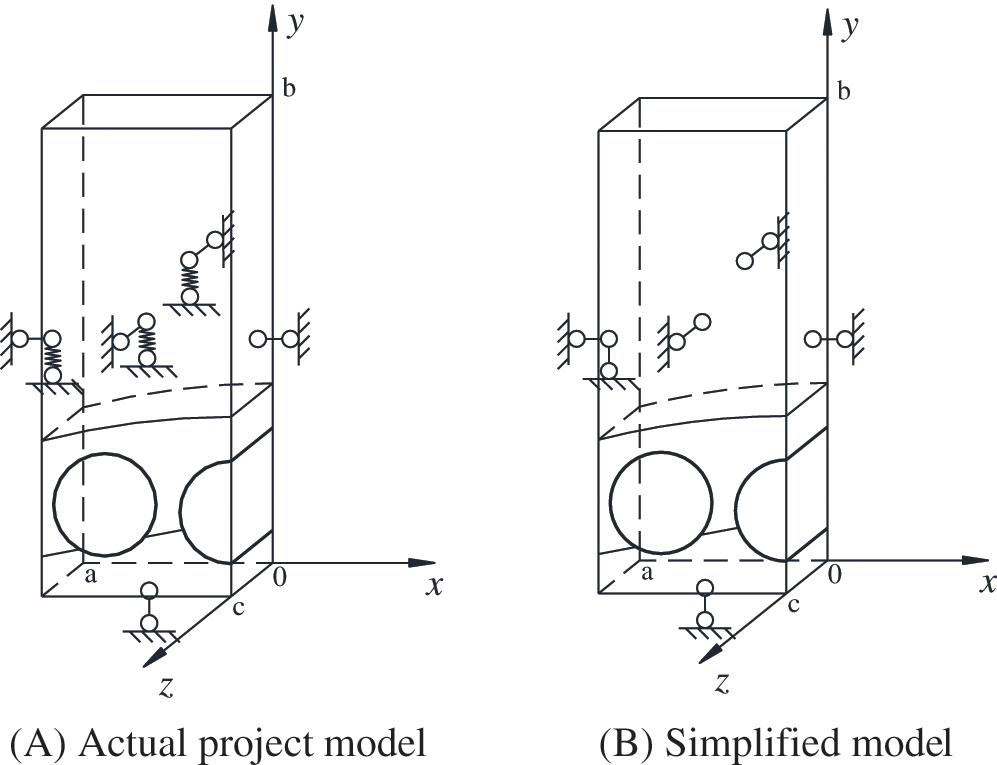
Figure 7: Boundary condition of hybrid regional model
The incomplete constrain mentioned above is related to the displacement and restraint capability of the face itself. The constraining force on the faces are different and the situation is more complicated. In Fig. 7A, the constraint is represented by a spring. Due to tunnel length of 255 m, the cross-sectional size and shape do not change along the tunnel excavation direction (
The balance of initial ground stress under asymmetric boundary conditions is the key to the implementation of hybrid regional model. Unlike full-scale model, the boundary condition of hybrid regional model will change after ground stress equilibration. In order to realize such process, the boundary condition of different direction should be added step by step. Thus, the process is divided into two steps. Fig. 8 is the front view of local symmetry model along the excavation direction. Fig. 8A represents the boundary condition when ground stress balances. There is only one direction boundary condition on the left face. The Fig. 8B represents the actual working condition. There are two directions boundary condition on the left face. The difference between two steps is the vertical constraint of the left boundary.
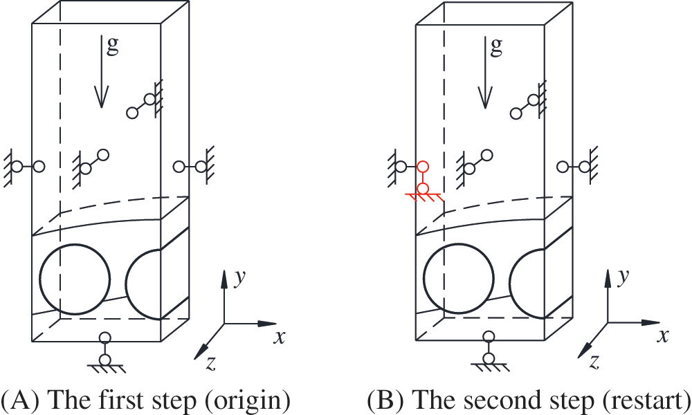
Figure 8: Two steps of boundary conditions for hybrid regional model
As the calculation flow described in Section 2, the first step and second step are respectively implemented by input file A and input file B. In file A, the result of ground stress equilibration is recorded and inputted to file B as initial step. In file B, boundary condition shown in Fig. 8B works after initialization.
There are gravity, water pressure and temperature in simulation. The initial soil temperature is 28°C. The water pressure is distributed evenly and the initial water pressure of ground surface is 0.
The simulation of this model considers the stress field [26–28], temperature field [29] and hydraulic field [30]. Each part satisfies the following equations. The constitutive model of Mohr-Coulomb is adopted in soil material [31].
(1) Solid equation can be expressed as Eq. (1)
where
For saturated porous media applications, it can be expressed as Eq. (2).
where
(2) Heat equation can be expressed as Eq. (3)
where
(3) Darcy flow equation can be expressed as Eq. (4)
where
(4) Mohr-coulomb model
The yield function is of the following type:
In which:
Among Eq. (5),
In which:
According to the governing equation above, the relationship between each one is associated through common parameters. Fig. 9 shows the coupling process of hydro-thermal-mechanical field, which is implemented in Dynaflow. The relationship between elastic module and temperature is in Eq. (7).
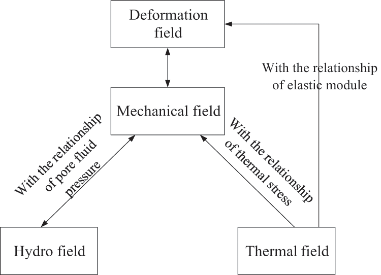
Figure 9: Schematic of the hydro-thermal-mechanical coupling process
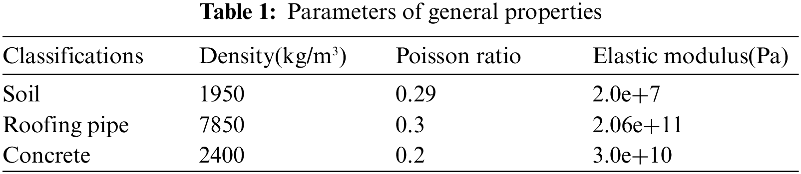
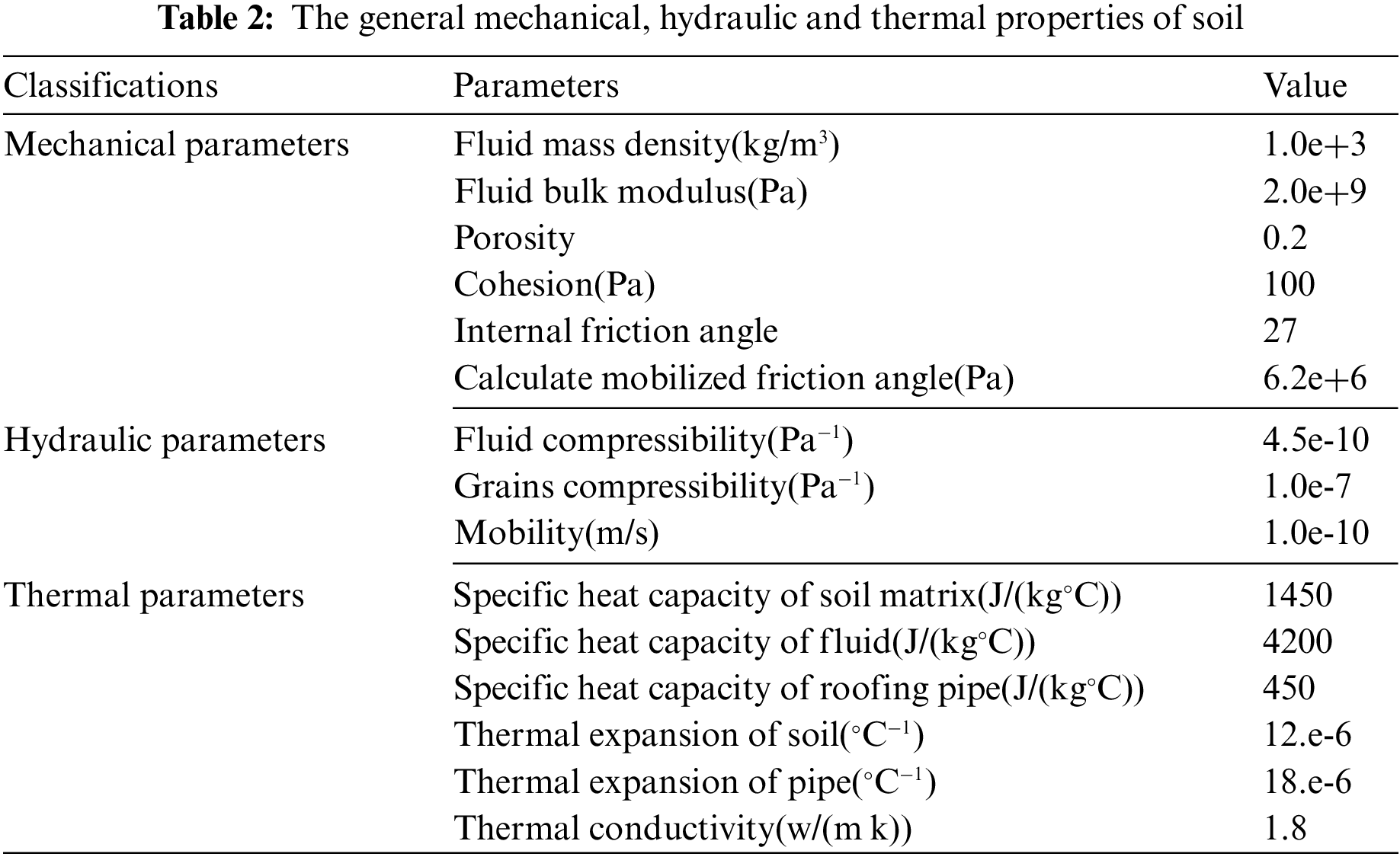
Soil material is simulated by Mohr-Coulomb yield criteria. Roofing pipes and concrete materials are set up on the basis of elastic theory. Due to the diversity of soil layers based on Chinese standard of JTG D63–2007, it is considered as homogeneous soil here for the convenience of analysis [32]. Table 1 shows different material parameters of this model [33]. Table 2 shows the mechanical, hydraulic and thermal properties of soil [34].
According to the test of laboratory, we know that the temperature have effect on the material parameters. The relationship of material parameters and temperature of frozen soil lists below, shown in Table 3. Thus, the functional relationships between elastic module and temperature is written into the finite element program by script.
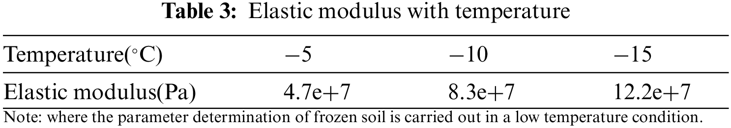
The fitting formula of elastic modulus is as follows, which represents the effect of temperature field on stress field.
where T satisfies the following range:
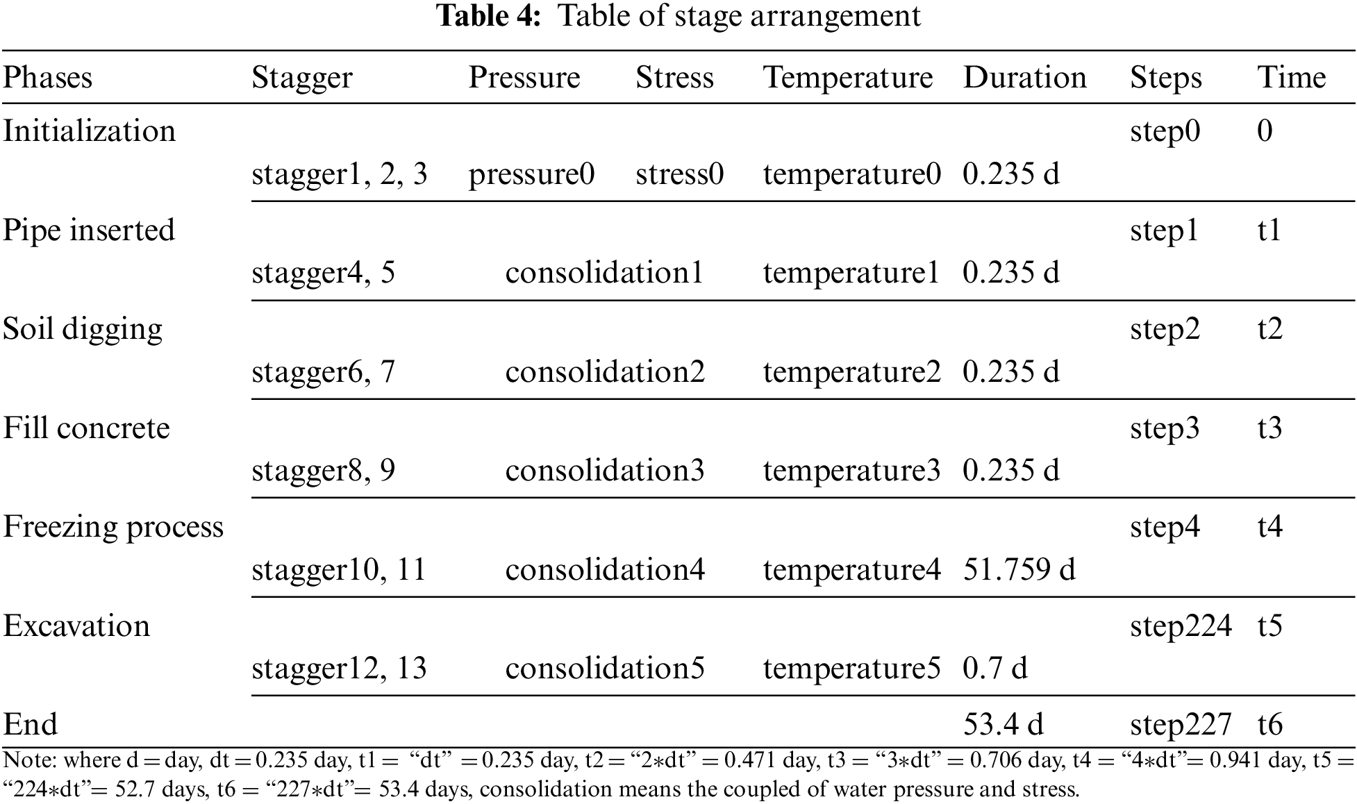
To make the step time of construction simulation as real as possible, time dependence should be taken into account. There are 227 steps of the numerical simulation, which contains the process of initialization, pipe jacking, soil digging, backfilling pipe with concrete, freezing, tunnel excavation. The time for each construction step is simulated and the arrangement of each step shows in Table 4.
The thermo-hydro-mechanical coupling model is divided into 9 zones, including 23 groups. It is illustrated by the following Table 5, which corresponds to script.
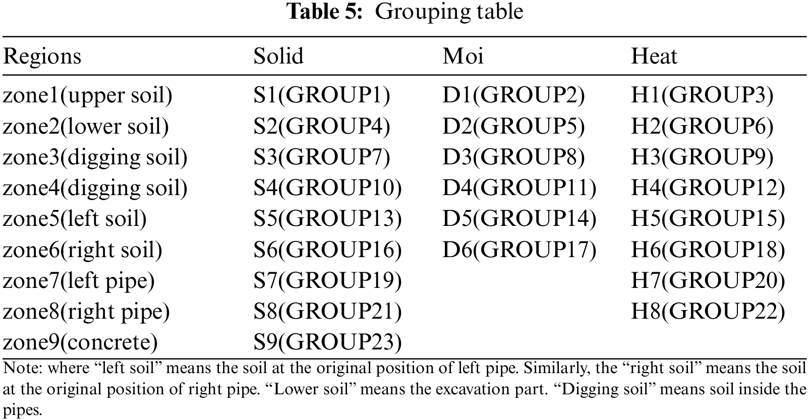
Partition sketch of each phase is shown in Fig. 10. The model of initialization contains zone1(S1,D1,H1), zone2(S2,D2,H2), zone3(S3,D3,H3), zone4(S4,D4,H4), zone5(S5,D5,H5), zone6(S6,D6,H6), shown in Fig. 10A. The pipe inserted phase contains zone1(S1,D1,H1), zone2(S2,D2,H2), zone3(S3,H3), zone4(S4,H4), zone7(S7,H7), zone8(S8,H8), shown in Fig. 10B, which indicates that the soil of zone5, zone6 in original area was replaced by the pipe of zone7, zone8. The soil digging phase contains zone1(S1,D1,H1), zone2(S2,D2,H2), zone7(S7,H7), zone8(S8,H8), which means the soil of zone3, zone4 was removed, shown in Fig. 10C. The phases of fill concrete and freezing process contains zone1(S1,D1,H1), zone2(S2,D2,H2), zone7(S7,H7), zone8(S8,H8), zone9(S9), which means the concrete element of zone9 was activated, respectively shown in Figs. 10D and 10E. The excavation phase contains zone1(S1,D1,H1), zone7(S7,H7), zone8(S8,H8), zone9(S9), which means the lower soil of zone2 was removed, shown in Fig. 10F.
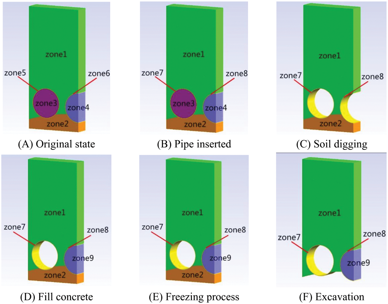
Figure 10: Partition sketch of each phase
4.1 Verification against Model Initialization
In order to assess the applicability of the proposed hybrid regional model, the construction simulation of Gongbei tunnel is performed. The first step is to verify the initialization of the model.
The duration of initialization is 0.22 day, which means enough time for distribute initial water pressure, temperature and ground stress. The initial vertical stress is assumed to be lithostatic. The experiments in laboratory were conducted to get the basic physical-mechanical parameters, which was directly relevant to simulated precision. The initialization is the key step to ensure the accuracy of model. The model of initialization contains zone1(S1,D1,H1), zone2(S2,D2,H2), zone3(S3,D3,H3), zone4(S4,D4,H4), zone5(S5,D5,H5), zone6(S6,D6,H6). Initial temperature is 28°C, shown in Fig. 11A. The temperature distribution is reasonable. Initial pore water pressure and ground stress have rational distribution, respectively shown in Figs. 11B and 11C. The initial pore water pressure is assumed to be hydrostatic pressure and the value gradually increases with depth. That is to say, the initial ground stress has a similar pattern to initial water pressure. As shown below, the initialization of temperature-water pressure-stress was successfully implemented, which verified the correctness of hybrid regional model.
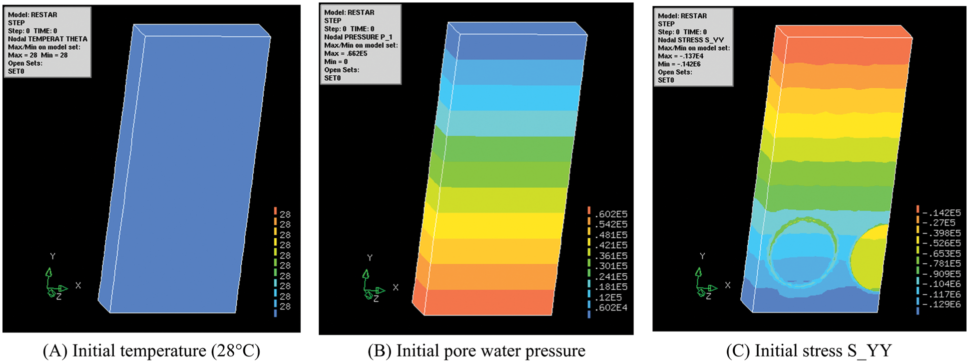
Figure 11: Initialization of temperature-water pressure-stress
4.2.1 Feature Points of the Model
In order to facilitate the analysis, typical feature points are set to describe the results. There are four feature points in the model, which are shown in Fig. 12. P1 is located in the ground surface. P2 is located in the top of the right steel pipe. P3 is located in the bottom of the right steel pipes. And P4 is located between two pipes. The temperature, water pressure and displacement are respectively analyzed.
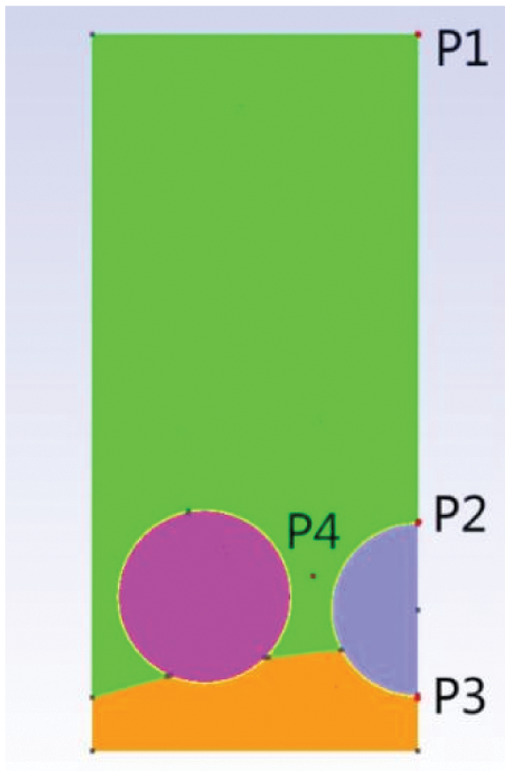
Figure 12: Feature points of the model
The artificial ground freezing technique is the key to the project. So temperature changes should be paid more attention. The initial temperature is 28°C, shown in Fig. 13A. After backfilling steel pipe with concrete, freezing process begin. The surface temperature of steel pipe is −10°C and spread all around, shown in Fig. 13B. According to Fig. 13C below, frozen curtain of over 2 m thickness is formed and maintained in 50 days. Thus the time for freezing is reasonable. And the thickness of frozen soil meet the requirements of 2 m.
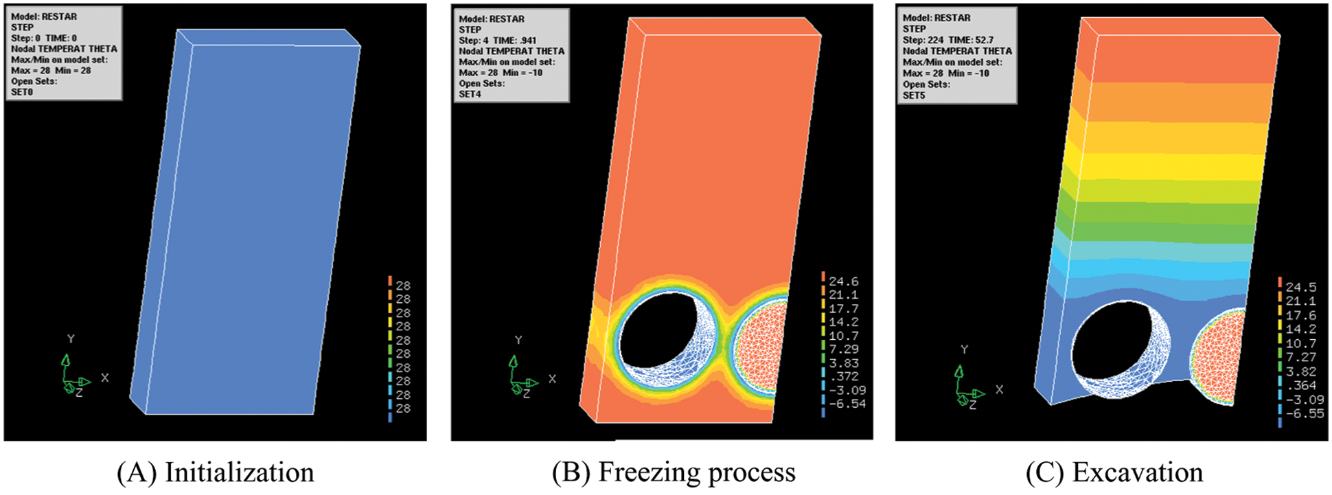
Figure 13: Temperature of each phase
Feature point P1 of ground surface is far away from cold source, and the cold amount is difficult to diffuse to ground surface in 50 days, so the temperature is always 28°C, shown in Fig. 14A. Feature point P2 and P3 was respectively located at the top and bottom of the right steel pipe. At first, the temperature is 28°C. Then the temperature suddenly drops to −10°C when freezing process begin, shown in Figs. 14B and 14C. P4 represents the soil temperature between steel pipes. The temperature gradually varies from 28°C to −8°C within 40 days during the freezing phase, shown in Fig. 14D. The temperature of feature points indicates that temperature change goes well and duration of freezing is reasonable.
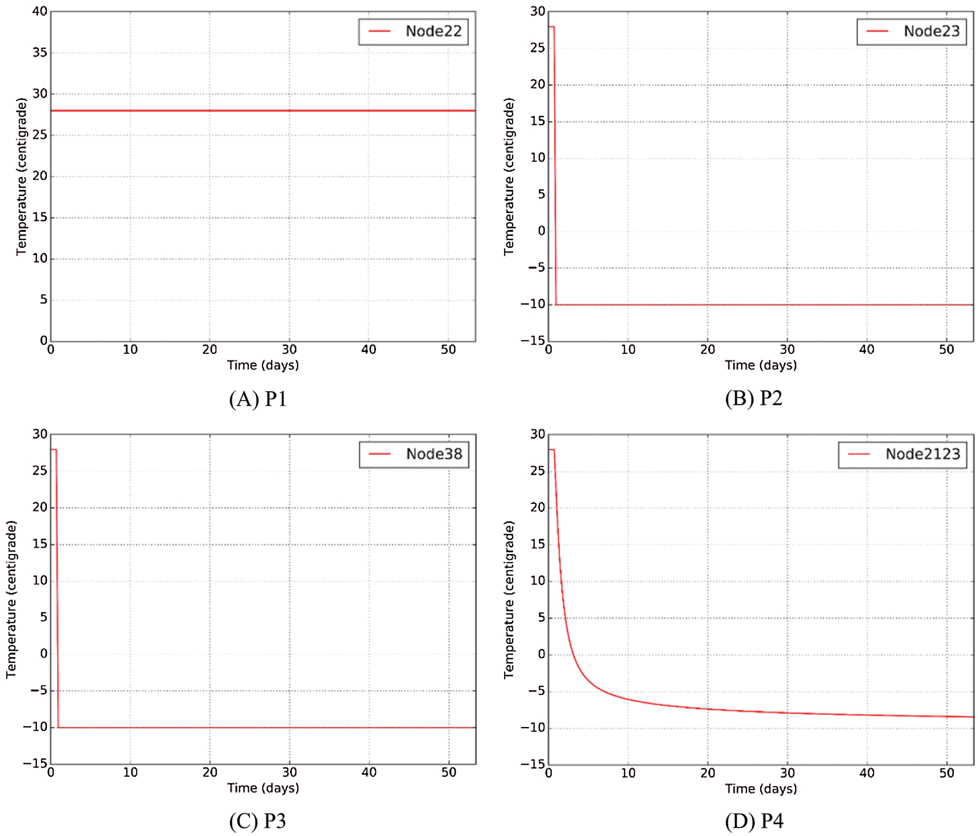
Figure 14: Temperature of feature point
Groundwater is one of the most important factors to influence the safety of tunnel construction. The distribution of water pressure ran uniformly in this project. The construction steps had only a little effect on it, and could be redistributed in short time. The value of ground surface point P1 is always 0 in Fig. 15A, because the construction had little effect on the position far away. Feature points P2 and P4 had the same law curve, which was respectively shown in Figs. 15B and 15D. The maximum water pressure reached 0.0465 MPa after backfilling the concrete. In the freezing process, the water pressure decreased with the time until smooth. When excavation, a sudden increase occurred and restored for redistribution in one or two days. There was a sudden drop in the water pressure about P3 when excavation, shown in Fig. 15C, because water pressure redistributed with the removing of bottom part. Thus, excavation step should be paid more attention to prevent leakage, which is a potential hazards in this project.
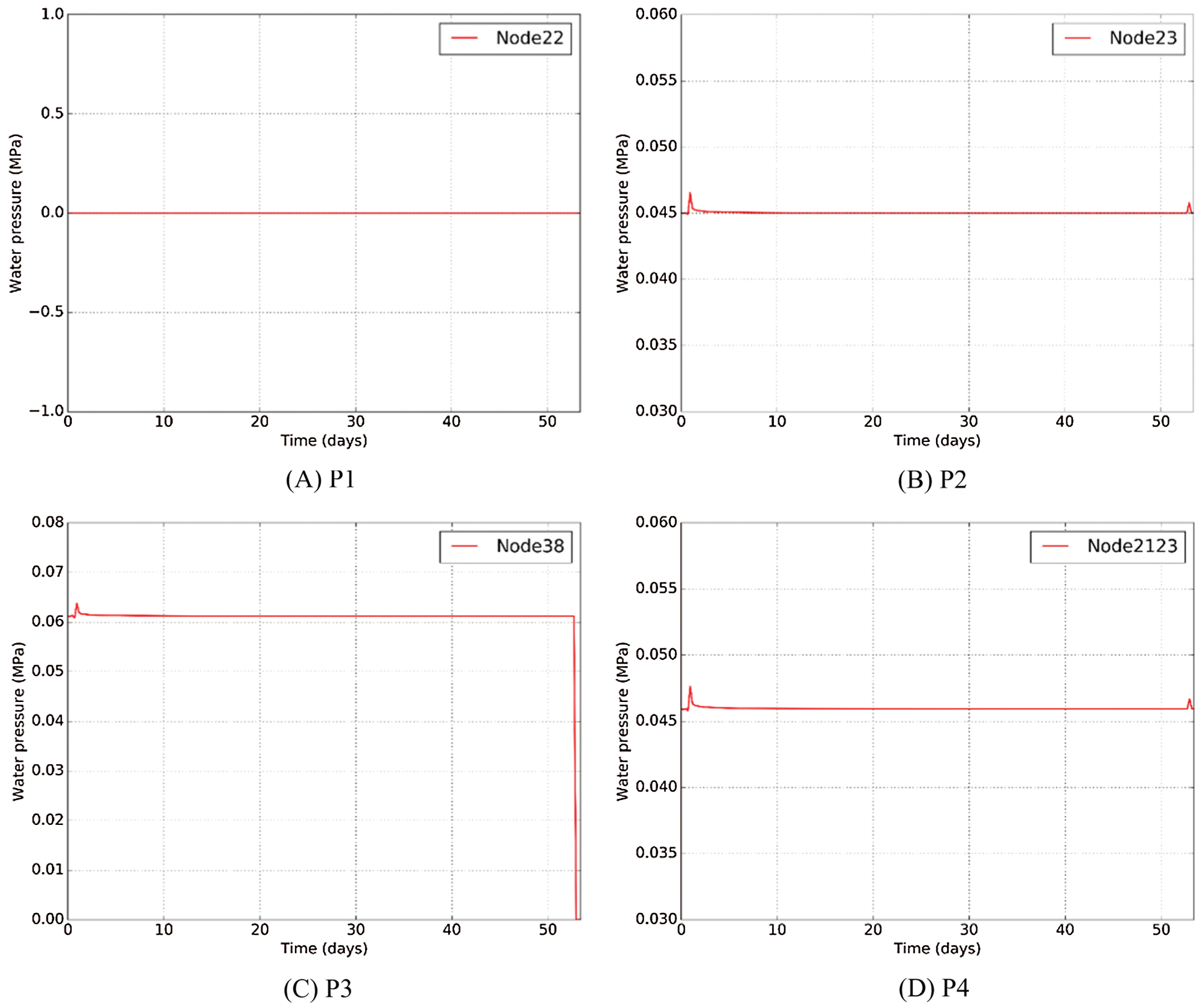
Figure 15: Water pressure of feature point
The deformation as an intuitive index varies with each step. To visualize the deformation of each construction step, vector diagram is used to display, shown in Fig. 16. Deformation changes at each step. The maximum deformation occurs during excavation phase. The deformation of ground surface increases from left to right.
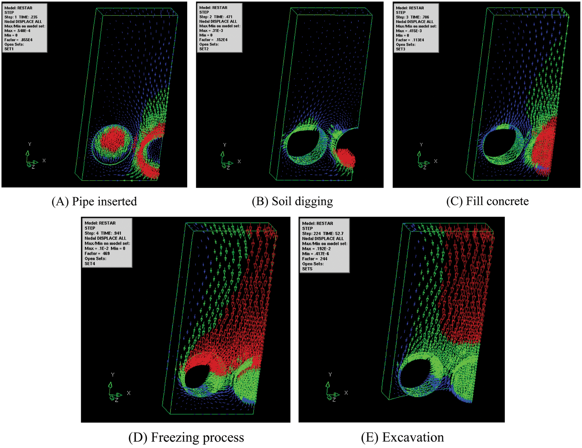
Figure 16: Vector diagram of each phase
The feature point P1 of ground surface decreases with the freezing process and rapidly decreases when excavation, shown in Fig. 17A. The maximum settlement of P1 is 3.01 mm. The vertical displacement of feature point P2 at the top of right steel pipe decreases with the temperature reducing and rapidly decreases when excavation, shown in Fig. 17B. The maximum vertical displacement of P2 is 4.26 mm, which is the maximum displacement among feature points. Meanwhile, the value is in an acceptable range of the project. The vertical displacement of feature point P3 at the bottom of right steel pipe decreases with the freezing process and rapidly decreases when excavation, shown in Fig. 17C. The maximum vertical displacement of P3 is 3.80 mm. The vertical displacement of feature point P4 between two steel pipes decreases with the freezing process and rapidly decreases when excavation, shown in Fig. 17D. The maximum vertical displacement of P4 is 1.82 mm.
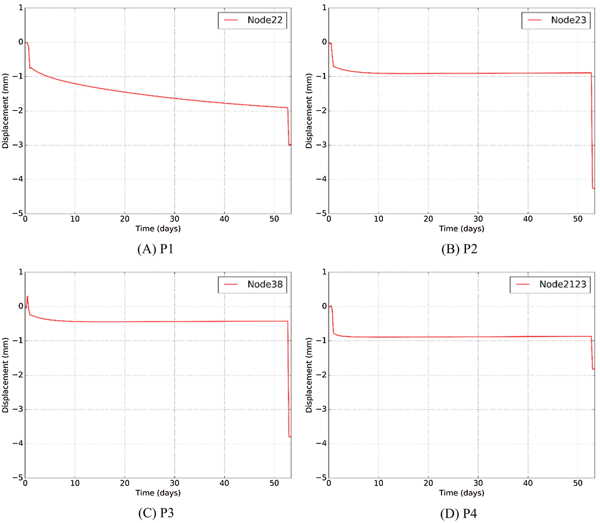
Figure 17: Vertical displacement of feature points
The maximum vertical displacement of each step was shown in Fig. 18. The maximum vertical displacement appeared at the top of right steel pipe with the value of 0.0548 mm when steel pipe was inserted. The maximum vertical displacement appeared at the bottom of right pipe with the value of 0.31 mm vertical up when the soil was removed. The maximum vertical displacement appeared at the top of right steel pipe with the value of 0.415 mm when the right steel pipe was filled with concrete. As the steel pipe has good rigidity, there is little displacement. At the beginning of freezing process, the vertical displacement changes to 1 mm with the effect of temperature and water pressure, which appeared at the center of ground surface. After excavation, the maximum vertical displacement appeared at the top of right steel pipe with the value of 4.26 mm.
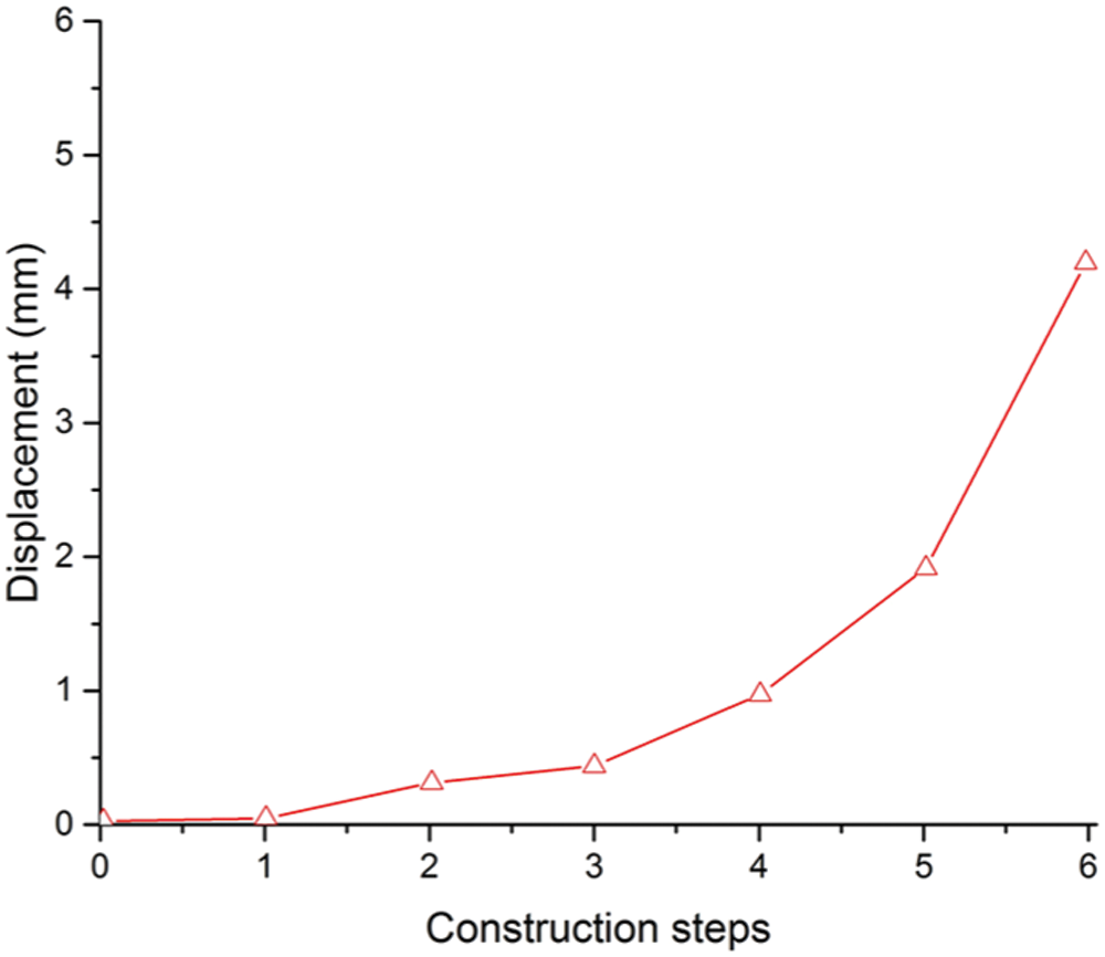
Figure 18: Maximum vertical displacement of each step
The deformation of ground surface was also an important index to reflect the safety of the project. Considering the symmetry of the model, the settlement curve presents the form of normal distribution. The maximum displacement of ground surface appeared at the point P1 with the value of −2.98 mm. In order to further verify the accuracy of the proposed hybrid regional model, the results calculated by the present method are compared with the monitoring data of actual project. As shown in Fig. 19, both two curves have a reasonable agreement. In addition, the large deviation of individual monitoring values is due to construction factors such as local grouting and frost heaving. Therefore, the result of the hybrid regional model is in a reasonable and acceptable range of this project.
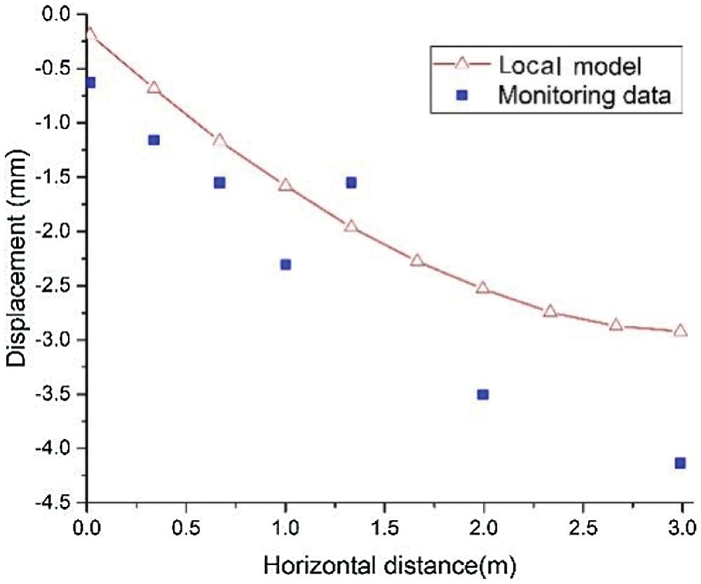
Figure 19: Displacement of ground surface after excavation
In this paper, a variable boundary condition method for hybrid regional model considering the thermal-hydro-mechanical coupling was used to simulate large-scale tunnel construction induced by excavation, and the model was validated against the initialization and deformation of Gongbei tunnel. Finally, it was compared with the monitoring data of ground surface deformation, and the following conclusions were drawn:
(1) The balance of initial ground stress under asymmetric boundary conditions was successfully implemented and verified through secondary development of DTNAFLOW script, which divided the application of boundary conditions into two phases.
(2) The accuracy of the proposed hybrid regional model was verified by comparing with the ground surface deformation of monitoring data, and the result indicated that regional model has good prediction effect.
(3) Based on regional model, the surface settlement curve of Gongbei tunnel presents the form of normal distribution. The maximum displacement of ground surface appeared above the top of concrete-filled steel pipe (point P1) with the value of −2.98 mm.
(4) According to the water pressure and deformation of Gongbei tunnel, the maximum vertical displacement occurred at the bottom of the right pipe after excavation. The value will reach to 4.26 mm without any support. Therefore, the phase of excavation had higher risk and should be paid more attention to. The time control for each construction step should be arranged properly, especially in the freezing and excavation steps. Besides, it might be more effective to set the temporary support at the bottom of the right pipe.
However, there are still have some shortcomings. For instance, the boundary conditions between hybrid regional model and actual engineering are not exactly the same and need further study. It should be noted that the application of the proposed hybrid regional model to Gongbei tunnel related cases will be a reference for similar large-scale underground engineering construction.
Acknowledgement: The authors wish to special thank Prof. Jean H. Prevost for the careful guidance as my supervisor during the studying period at Princeton University as VSRC scholar. Also thanks to the high-performance computing cluster of Computer Science Department at Princeton University and the editor Dr. Aubrey Dou for her careful format review.
Funding Statement: This work is supported by the financial support from National Natural Science Foundation of China (No. 51478340), Natural Science Foundation of Jiangsu Province (No. BK20200707), Natural Science Foundation of the Jiangsu Higher Education Institutions of China (No. 20KJB560029), China Postdoctoral Science Foundation (No. 2020M671670), Key Laboratory of Soft Soils and Geoenvironmental Engineering (Zhejiang University), Ministry of Education (No. 2020P04). The support above is gratefully acknowledged.
Conflicts of Interest: The authors declare that they have no conflicts of interest to report regarding the present study.
References
1. Zheng, L., Gao, Y., Zhou, Y., Liu, T., Tian, S. (2021). A practical method for predicting ground surface deformation induced by the artificial ground freezing method. Computers and Geotechnics, 130, 1–16. DOI 10.1016/j.compgeo.2020.103925. [Google Scholar] [CrossRef]
2. Li, F., Chen, G. (2020). Study on deformation characteristics of ground surface settlement during shield tunnel construction of river floodplain in Nanjing. Journal of the China Railway Society, 42(7), 155–160. DOI 10.3969/j.issn.1001-8360.2020.07.020. [Google Scholar] [CrossRef]
3. Ruan, H., Wang, Y., Wan, Y., Yu, X., Zeng, C. et al. (2021). Three-dimensional numerical modeling of ground deformation during shield tunneling considering principal stress rotation. International Journal of Geomechanics, 21(7), 04021095. DOI 10.1061/(ASCE)GM.1943-5622.0002048. [Google Scholar] [CrossRef]
4. Zhang, T., Ge, L., Zheng, G. (2019). Deformation of surface and subsurface ground due to tunnel excavation in sand. Tianjin Daxue Xuebao/Journal of Tianjin University Science and Technology, 52, 113–119. DOI 10.11784/tdxbz201902030. [Google Scholar] [CrossRef]
5. Wang, W., Kosakowski, G., Kolditz, O. (2009). A parallel finite element scheme for thermo-hydro-mechanical (THM) coupled problems in porous media. Computers & Geosciences, 35(8), 1631–1641. DOI 10.1016/j.cageo.2008.07.007. [Google Scholar] [CrossRef]
6. Arson, C., Gatmiri, B. (2012). Thermo-hydro-mechanical modeling of damage in unsaturated porous media: Theoretical framework and numerical study of the EDZ. International Journal for Numerical and Analytical Methods in Geomechanics, 36(3), 272–306. DOI 10.1002/nag.1005. [Google Scholar] [CrossRef]
7. Rucker, C., Gunther, T., Spitzer, K. (2006). Three-dimensional 3D modelling and inversion of DC resistivity data incorporating topography-I. Geophysical Journal International, 166(2), 495–505. DOI 10.1111/j.1365-246X.2006.03010.x. [Google Scholar] [CrossRef]
8. Liu, Z. J., Zheng, H., Dong, W., Ge, X., Sun, G. (2017). Local mesh refinement in numerical manifold method based on refined physical patches. Rock and Soil Mechanics, 38(4), 1211–1217. DOI 10.16285/j.rsm.2017.04.036. [Google Scholar] [CrossRef]
9. Ye, L., Li, Y., Liu, Y., Li, G., Yang, H. (2016). 3D finite element modeling of marine controlled-source electromagnetic fields using locally refined unstructured meshes. Chinese Journal of Geophysics, 59(12), 4747–4758. DOI 10.6038/cjg20161233. [Google Scholar] [CrossRef]
10. Chen, L. (2016). Analysis of mechanical behavior of whole bridge and key parts for a long-span railway continuous steel truss girder bridge (Master Thesis). Central South University, China. [Google Scholar]
11. Loganathan, N., Poulos, H. G. (1998). Analytical prediction for tunneling-induced ground movements in clays. Journal of Geotechnical and Geoenvironmental Engineering, 124(9), 846–856. DOI 10.1061/(ASCE)1090-0241(1998)124:9(846). [Google Scholar] [CrossRef]
12. Yang, S., Tao, Y., Xu, P. (2019). Large-scale model experiment and numerical simulation on convergence deformation of tunnel excavating in composite strata. Tunnelling and Underground Space Technology, 94, 103–133. DOI 10.1016/j.tust.2019.103133. [Google Scholar] [CrossRef]
13. Yue, J., Li, W., Gao, P., Zhang, S. (2021). Development and application of large-scale model test system for underwater shield tunnels. Proceedings of the Institution of Civil Engineers-Structures and Buildings, 174(12), 981–991. [Google Scholar]
14. Prevost, J. H. (1983). Dynaflow (version 02 release 10.A). USA: Princeton University. [Google Scholar]
15. Geuzaine, C., Remacle, J. F. (2009). Gmsh: A three-dimensional finite element mesh generator with built-in pre- and post-processing facilities. International Journal for Numerical Methods in Engineering, 79(11), 1309–1331. DOI 10.1002/nme.2579. [Google Scholar] [CrossRef]
16. Arno, W., Jonna, M. (2010). FemGV user's manual release 7.2 release notes. TNO Diana BV, the Netherlands. [Google Scholar]
17. Liu, J. G., Ma, B. S., Cheng, Y. (2018). Design of the Gongbei tunnel using a very large cross-section pipe-roof and soil freezing method. Tunnelling and Underground Space Technology, 72, 28–40. DOI 10.1016/j.tust.2017.11.012. [Google Scholar] [CrossRef]
18. Pan, J., Gao, H., Shi, P. (2015). A study of combined pipe-roof scheme optimization for the bored section of the Gongbei tunnel. Modern Tunnelling Technology, 52(3), 55–62. DOI 10.13807/j.cnki.mtt.2015.03.008. [Google Scholar] [CrossRef]
19. Hu, X., Deng, S., Ren, H. (2017). In situ test study on freezing scheme of freeze-sealing pipe roof applied to the Gongbei tunnel in the Hong Kong-Zhuhai-Macau Bridge. Applied Sciences, 7(1), 27. DOI 10.3390/app7010027. [Google Scholar] [CrossRef]
20. Hu, X., Deng, S., Wang, Y. (2018). Test investigation on mechanical behavior of steel pipe-frozen soil composite structure based on freeze-sealing pipe roof applied to Gongbei tunnel. Tunnelling and Underground Space Technology, 79, 346–355. DOI 10.1016/j.tust.2018.06.033. [Google Scholar] [CrossRef]
21. Hu, X., Deng, S., Wang, Y. (2018). Mechanical tests on bearing capacity of steel pipe-frozen soil composite structure applied in Gongbei tunnel. Chinese Journal of Geotechnical Engineering, 40(8), 1–10. DOI 10.11779/CJGE201808014. [Google Scholar] [CrossRef]
22. Wang, Y. (2013). Mechanical property analysis of steel pipe-frozen soil composite structure in freeze-sealing pipe roof method (Master Thesis). Tongji University, China. [Google Scholar]
23. Zhang, W. (2016). Experimental study on mechanical behavior of steel pipe-frozen soil composite structure in freeze-sealing pipe roof method (Master Thesis). Tongji University, China. [Google Scholar]
24. Zhang, P., Ma, B., Zeng, C., Xie, H., Li, X. et al. (2016). Key techniques for the largest curved pipe jacking roof to date: A case study of Gongbei tunnel. Tunnelling and Underground Space Technology, 59, 134–145. DOI 10.1016/j.tust.2016.07.001. [Google Scholar] [CrossRef]
25. Zhang, P., Behbahani, S. S., Ma, B. S. (2018). A jacking force study of curved steel pipe roof in Gongbei tunnel: Calculation review and monitoring data analysis. Tunnelling and Underground Space Technology, 72, 305–322. DOI 10.1016/j.tust.2017.12.016. [Google Scholar] [CrossRef]
26. Prevost, J., Tao, D. (1983). Finite element analysis of dynamic coupled thermoelastic problems with relaxation times. Journal of Applied Mechanics, 50, 817–822. DOI 10.1115/1.3167151. [Google Scholar] [CrossRef]
27. Tao, D., Prevost, J. (1984). Relaxation effects on generalized thermoelastic waves. Journal of Thermal Stresses, 7, 79–89. DOI 10.1080/01495738408942197. [Google Scholar] [CrossRef]
28. Tao, D. (1984). Finite element analysis of thermo elasticity problems (Ph.D. Thesis). Princeton University, USA. [Google Scholar]
29. Prevost, J. (1982). Nonlinear transient phenomena in saturated porous media. Computer Methods in Applied Mechanics and Engineering, 30(1), 3–18. DOI 10.1016/0045-7825(82)90052-4. [Google Scholar] [CrossRef]
30. Masud, A., Hughes, T. (2002). A stabilized mixed finite element method for darcy flow. Computer Methods in Applied Mechanics and Engineering, 191, 4341–4370. DOI 10.1016/S0045-7825(02)00371-7. [Google Scholar] [CrossRef]
31. Prevost, J. (1978). Plasticity theory for soil stress-strain behavior. Journal of Engineering Mechanics, 104(5), 1177–1194. DOI 10.1061/JMCEA3.0002411. [Google Scholar] [CrossRef]
32. Ministry of Transport (2019). Code for design of ground base and foundation of highway bridges and culverts (JTG 3363—2019). China: People's Communications Press. [Google Scholar]
33. Ministry of Construction (1999). Standard for soil test method (GB/T 50123-1999). China: China Planning Press. [Google Scholar]
34. State Administration of Work Safety (2011). Artificial frozen soil physics mechanics performance test (MT/T 593–2011)0. China: Coal Industry Standard of the People's Republic of China. [Google Scholar]
Cite This Article
 Copyright © 2023 The Author(s). Published by Tech Science Press.
This work is licensed under a Creative Commons Attribution 4.0 International License , which permits unrestricted use, distribution, and reproduction in any medium, provided the original work is properly cited.
 Downloads
 Citation Tools