| Computer Modeling in Engineering & Sciences |
DOI: 10.32604/cmes.2022.020523
ARTICLE
Research on Distributed Cooperative Control Strategy of Microgrid Hybrid Energy Storage Based on Adaptive Event Triggering
1School of Electrical and Control Engineering, Shaanxi University of Science and Technology, Xi'an, 710021, China
2School of Mathematics and Computer Science, Yan'an University, Xi'an, 716000, China
3School of Automation, Northwestern Polytechnical University, Xi'an, 170072, China
*Corresponding Author: Jingwen Chen. Email: chenjw@sust.edu.cn
Received: 29 November 2021; Accepted: 20 December 2021
Abstract: Distributed collaborative control strategies for microgrids often use periodic time to trigger communication, which is likely to enhance the burden of communication and increase the frequency of controller updates, leading to greater waste of communication resources. In response to this problem, a distributed cooperative control strategy triggered by an adaptive event is proposed. By introducing an adaptive event triggering mechanism in the distributed controller, the triggering parameters are dynamically adjusted so that the distributed controller can communicate only at a certain time, the communication pressure is reduced, and the DC bus voltage deviation is effectively reduced, at the same time, the accuracy of power distribution is improved. The MATLAB/Simulink modeling and simulation results prove the correctness and effectiveness of the proposed control strategy.
Keywords: DC microgrid; hybrid energy storage; adaptive event trigger; distributed collaborative control
In recent years, the development of renewable energy and power electronics has continuously driven the progress of distributed generation, microgrid, and other technologies. Since the DC microgrid can improve the efficiency of power generation and has the advantages of high reliability and low power generation cost [1–3], it has received great attention from scientific researchers [4–7]. However, distributed power generation is intermittent, which leads to power fluctuation and affects the stability of the microgrid. Therefore, the microgrid needs to be combined with energy storage devices to reduce the impact of unbalanced power on the system and improve its stability of the system. Reasonable power allocation for multiple sets of hybrid energy storage power is one of the goals of the coordinated control of optical storage microgrid [8].
At present, the DC microgrid multi-group hybrid energy storage control strategy mainly includes centralized control, distributed control, and decentralized control [9]. Droop control is the most commonly used method of distributed control, in which voltage and current are adjusted by adding a virtual impedance. However, due to the impedance of the circuit, there is still some voltage and current error [10–14]. A central controller is used to compensate for the voltage deviation and accurate current sharing. However, if one of the communication channels fails, it directly leads to the instability of the whole system and causes cascading failures with low reliability [15–20].
To overcome the limitations of the above methods, some researchers have proposed consensus-based distributed control. Each exchange state information with its neighbors and updates its control signals in real-time in combination with its state to finally completes the goal of coordinated control [21–23]. However, in practical applications, the working mode of communication with fixed periods is usually selected, which leads to too frequent updating of system control, high energy consumption, high communication resource requirement and excessive computation [24,25].
To solve the above problem, some researchers have proposed an event trigger control method based on non-periodic data exchange communication [26]. The event is triggered only when the state error exceeds the trigger threshold, which reduces the communication volume to ensure the control performance of the system. Pullaguram et al. [27] proposed dynamic consensus algorithm based on event-triggered communication, which is helpful to achieve the goal of average voltage regulation and proportional current allocation. Han et al. [28] introduced a distributed nonlinear controller and introduced an improved event triggering principle to achieve accurate current equalization and voltage regulation. Guo et al. [29] presented a hierarchical distributed control method by using the idea of event-triggered communication and dc bus voltage feedback. Qian et al. [30] introduced a secondary voltage and frequency control strategy, and reduced the updating times of the controller by adopting the event triggering mode. Zhang et al. [31] proposed a cooperative control strategy for isolated island microgrid, designing event triggering mechanism, packet loss and communication burden in communication process can be reduced on the basis of ensuring voltage and frequency stability of microgrid. Yan et al. [32] used an event triggering mechanism based on adaptive adjustment parameters to save communication network space based on packet loss problem in communication network during information transmission between microgrid and large grid. In [33], a distributed control strategy based on event triggering is proposed to solve the secondary voltage frequency control problem of isolated island microgrid, which enables the controller to communicate at a specific moment and reduces the communication burden of the system. Wang et al. [34] presented a distributed control scheme based on dynamic event triggering mechanism for the microgrid composed of distributed micro-source and energy storage system, which balances the power between micro-source and energy storage and reduces the communication times between controllers.
The event trigger thresholds studied in the above literature are all fixed values, as well as unable to respond in a timely and effective manner to sudden changes in the system, and it ignores changes in system performance.
Therefore, in this paper, an adaptive event triggering mechanism with a variable triggering threshold is developed, which can adaptively adjust the triggering threshold when the system conditions change suddenly so that the system can reach a steady state as soon as possible. Compared with the traditional event trigger control, it reduces the communication pressure of the system. Compared with traditional event trigger control, it reduces the communication pressure of the system.
The rest chapters are arranged as follows: The second part introduces the structure of optical storage DC microgrid; In the third part, the distributed control strategy of hybrid energy storage based on adaptive event triggering is proposed, and its stability and convergence are proved. In the fourth part, the simulation is carried out to verify the proposed control strategy. The fifth part summarizes the thesis.
2 DC Microgrid Structure with Multi-Group Hybrid Energy Storage System
This article takes the isolated DC microgrid as the research object. The structure of the microgrid is shown in Fig. 1, which includes photovoltaic power generation units, multiple groups of hybrid energy storage units, load units, converters and distributed communication network units, the above units can be divided into three layers: physical layer, control layer and communication layer. The physical layer is the bottom structure of the microgrid. The photovoltaic power generation system and the energy storage unit are connected to the DC bus through the converter, and then the converter supplies power to the load. The control layer is used to adjust the duty cycle of the converter, and then control the output current of the power generation unit and the energy storage unit, the communication layer mainly provides information exchange for each energy storage unit to optimize the control of microgrid.
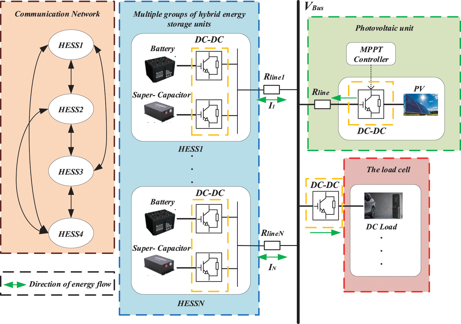
Figure 1: Structure diagram of DC microgrid with multiple groups of hybrid energy storage systems
To improve energy utilization, the photovoltaic system operates in maximum power mode and does not participate in distributed control between hybrid energy storage systems. Each energy storage system is composed of supercapacitors and batteries. When the load suddenly changes, the hybrid energy storage system balances the unbalanced power in the system to ensure the stable operation of the microgrid.
3 Distributed Cooperative Control Strategy for Hybrid Energy Storage Based on Adaptive Event Triggering
This paper proposes a distributed control to reasonably distribute the unbalanced power between HESSs. First, distribute the power between HESSs through droop control based on virtual resistance. Secondly, use the distributed collaborative control based on the consistency theory, and realize the information exchange between HESSs through the communication network, the event trigger mechanism is introduced to compensate the bus voltage drop during the droop control process, improve the power distribution accuracy, reduce the consumption of system communication resources, and realize the stable operation of the system.
3.1 Distributed Cooperative Control Strategy for Hybrid Energy Storage
At present, most optical storage micro networks use droop control based on virtual resistance, and the control structure is shown in Fig. 2.
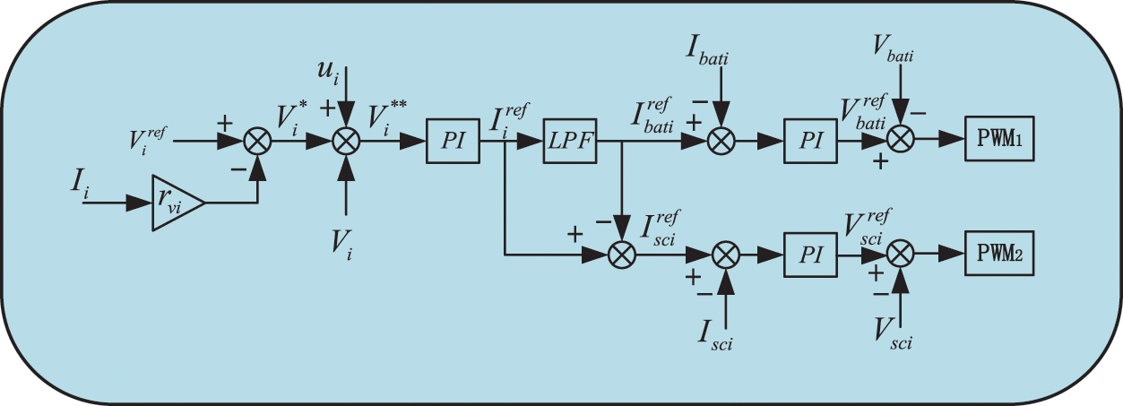
Figure 2: Droop control block diagram
Considering that there is a certain line resistance in the actual DC microgrid, the output current of each HESS cannot be accurately distributed in accordance with the set proportion, and there is a contradiction between the current distribution accuracy and voltage deviation, this paper proposes a distributed cooperative control strategy of hybrid energy storage based on adaptive event triggering.
The communication network in Fig. 1 can realize information exchange between various Hybrid Energy Storage Systems (HESS) in the microgrid system. The communication network used in this article is an undirected graph. For a system composed of n nodes, their topological relationship diagram is described by graph G,
3.1.2 Design Strategy of the Control System
The vital purpose of the distributed cooperative control based on consistency theory is to compensate for the bus voltage drop caused by droop control and reduce the voltage and current deviation between each HESS. Adjust the global voltage and current in the DC microgrid by readjusting the voltage and current setpoints in the HESSs converter control process to achieve average voltage and proportional current sharing. The distributed control block diagram is shown in Fig. 3.
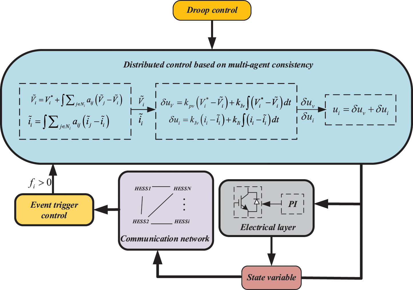
Figure 3: Block diagram of distributed control
Due to the existence of line resistance, the voltage of HESS output terminal is lower than the voltage of DC bus. In order to reduce this influence, HESSi is made to communicate with the voltage and current of adjacent HESSj and finally approaches the bus voltage rating. The voltage of each HESS is obtained after distributed control, and the reference value of the control voltage is:
Due to the existence of line resistance, the system cannot accurately achieve current distribution according to a given proportion, so the dynamic uniform current is introduced:
Take the derivative of both sides of (3) at the same time:
The difference of the voltage between droop controls the distributed control is obtained and sent to the PI controller to get the compensation voltage. The difference between the HESS current obtained through distributed control and the actual output current of the corresponding HESS is sent to the PI controller to obtain the compensation voltage to realize proportional current sharing, and finally, get a new voltage reference value as Eq. (7), realize the compensation of bus voltage drop caused by droop control.
3.1.3 Analysis of Convergence of Control Strategy
This section mainly proves the convergence of consistency theory. Combining Eqs. (2) and (4), they can be written in the following form:
By using the information exchange between neighbors, the control law is designed to achieve the consistency of HESS states, the control law is as follows:
Theorem. For graph G, the initial state of each node is
Proof: ① The known system state equation is
When
Bring
When
where
② The out degree of each node in graph G is equal to the in degree,
And satisfied
Take the right eigenvector of eigenvalue
From Eq. (12), we can get:
Combined Eq. (13),
It can be seen that when the system is in a steady state, the individual states all converge to the average value of the initial state. Combined with HESS system in microgrid, the average voltage and current are finally regulated by consistent distributed control.
The above-mentioned distributed cooperative control can realize the regulation of the DC bus voltage, However, there are periodic communications between adjacent HESSs. But when the system reaches a steady state, there is no need to change the control signal, the periodic communication carried out at this time will cause a waste of communication resources. Therefore, this paper proposes adaptive event trigger control, which reduces the pressure of system communication by changing the trigger threshold in real time. The following is the design process of an adaptive event-triggering function.
3.2 Adaptive Event Triggering Control
3.2.1 Event Trigger Function Design
Combining Eqs. (2) and (4), the i-th HESS reference voltage and current dynamic equation can be obtained as:
Written in uniform form:
where
The difference between the latest trigger time information of
Take the difference between the sampling information of
From Eqs. (25)–(26), the HESS system state can be obtained as:
Define the event trigger condition of
Establish an adaptive trigger function
Trigger parameter
The larger the event trigger parameter
3.2.2 Stability Analysis of Adaptive Event Triggering Control Strategy
In order to prove the stability and convergence of the system after using event-triggered control, define Lyapunov function
Bring Eq. (28) into (32), and make
where,
Define the vector, and
Introduce the event-triggered functional Eq. (29), and bring (35) into (34) to get:
When the event trigger parameter satisfies
It can be seen that the HESS system can be gradually stabilized under the control protocol (24) and adaptive event trigger condition (29).
4 Simulation Verification and Analysis
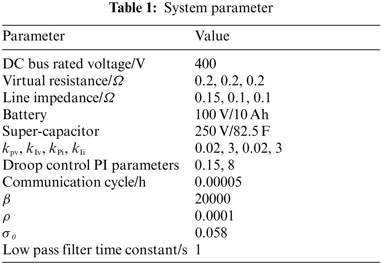
In order to verify the feasibility and effectiveness of the proposed control strategy, a simulation model is built under the Matlab/Simulink environment as shown in Fig. 1, and the system parameters are shown in Table 1.
Select 3 groups of HESSs systems to form an undirected connected topology, as shown in Fig. 4.
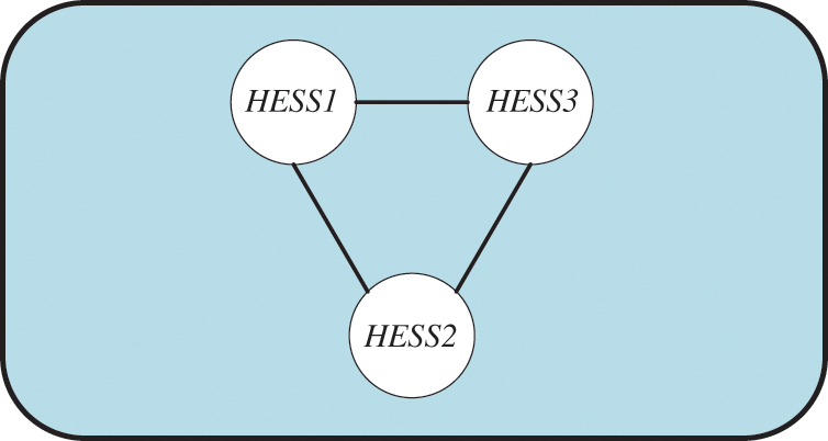
Figure 4: System topology
The Laplacian matrix corresponding to Fig. 4 is
4.1 Simulation and Verification of Distributed Cooperative Control Strategy
The battery SOC of the three groups of hybrid energy storage is 0.85, 0.75, 0.65, and the initial voltage of the supercapacitor is 200 V. The voltage and current status information of the three groups of HESS are exchanged through the communication network. The load is suddenly reduced at 3 s, 7 s Sudden load increase, compared to droop control and distributed cooperative control DC bus voltage changes.
Fig. 5 is a Simulink simulation model built according to Fig. 1, including three hybrid energy storage devices and photovoltaic power generation modules. The photovoltaic converter works in MPPT mode and does not participate in hybrid energy storage power distribution.
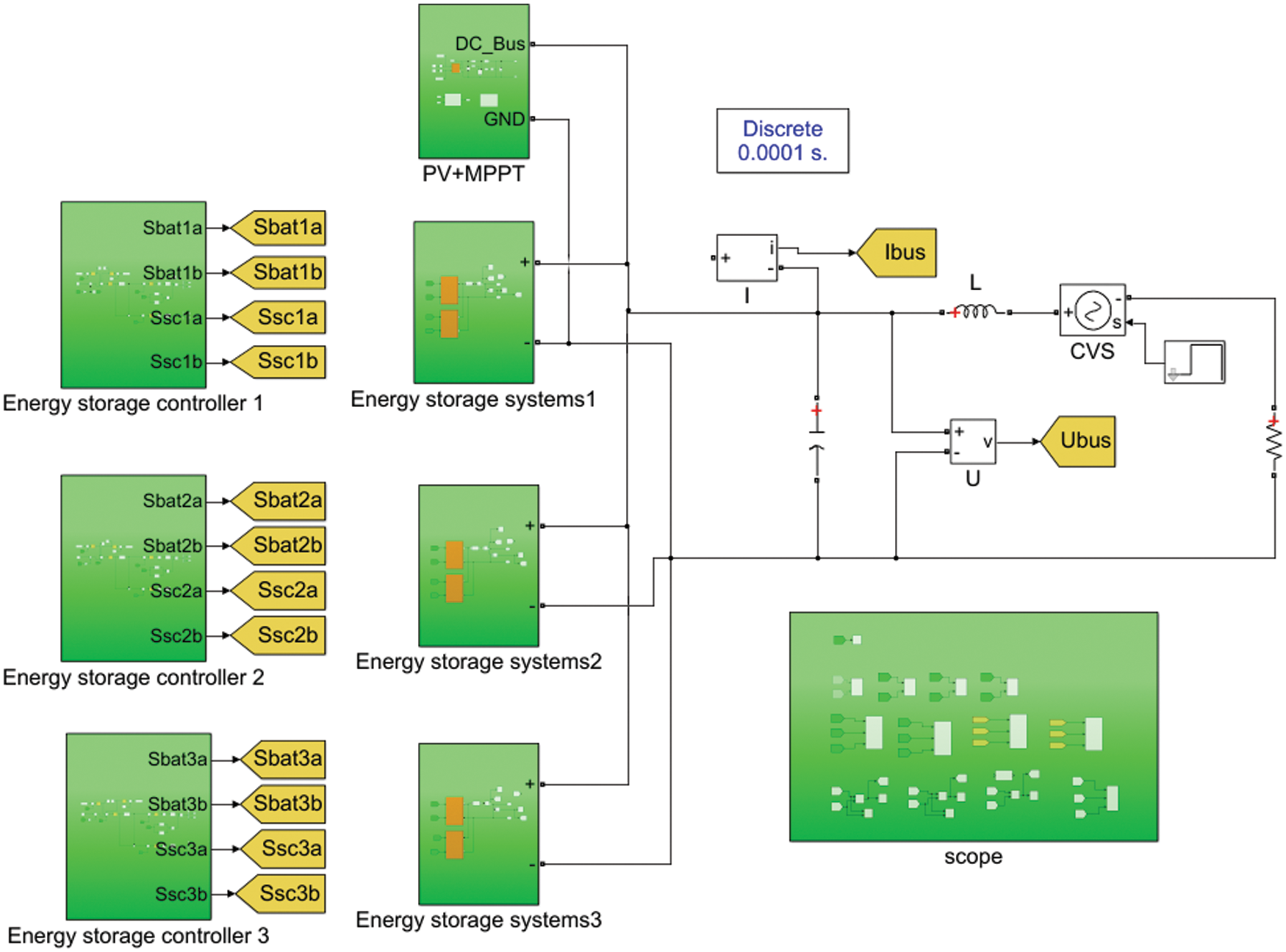
Figure 5: Simulation model structure diagram
It can be seen from Fig. 6 that the traditional droop control cannot compensate for the bus voltage drop loss caused by the line impedance, so the bus voltage is lower than the set bus voltage. In contrast, the distributed control can compensate the bus voltage to make the DC bus voltage closer to its setting rating.
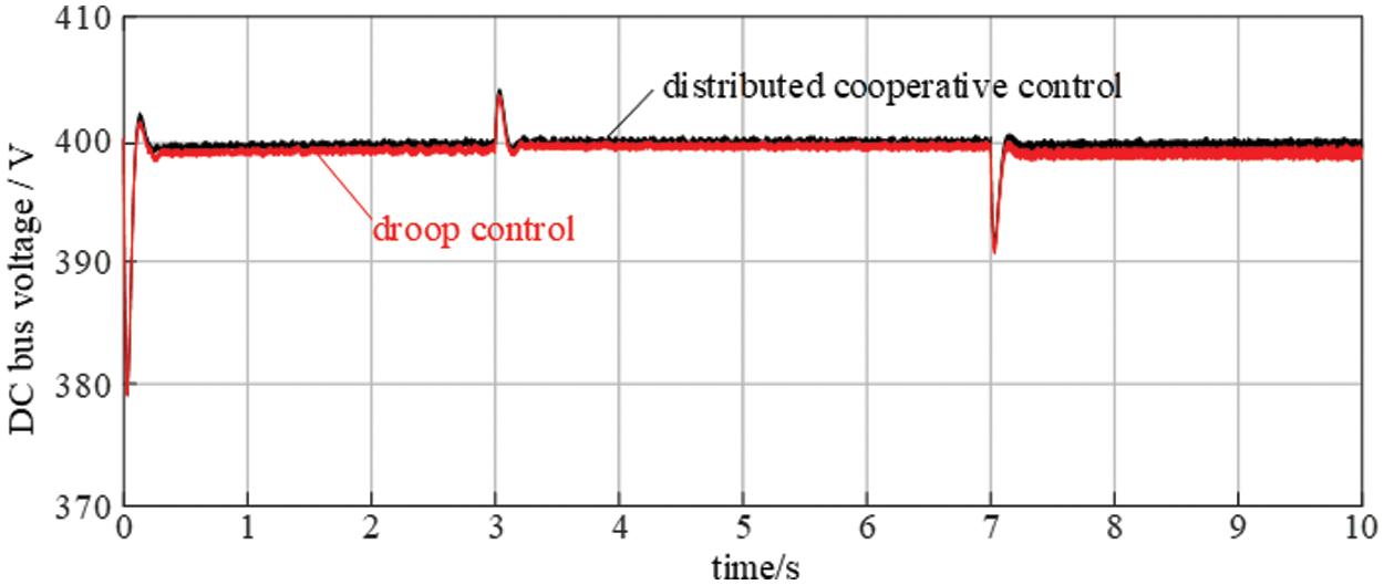
Figure 6: Comparison of bus voltages under the two control methods
Figs. 7 and 8 respectively show the variation curves of the output power of the supercapacitor and battery under the distributed cooperative control strategy. It can be seen that in the system startup stage, the supercapacitor and battery discharge to maintain the bus voltage, and the battery output power continues to increase, while the supercapacitor output power increases instantly and then gradually recovers to 0, combined with Figs. 9 and 10, it can be seen that the SOC of the two types of energy storage batteries decreases to meet their charge-discharge characteristics. At 3 s, the load drops suddenly and the hybrid energy storage is charged, so its output power decreases. Due to the slow response speed of the battery, its SOC cannot increase instantly, but the decreasing rate becomes slow. However, the response speed of the ultracapacitor is fast, so its SOC increases instantly. At the moment of 7 s, the load increases suddenly, and the mixed energy storage starts to discharge again. The output power of both batteries increases, and the battery SOC decreases at a faster rate, while the supercapacitor SOC decreases instantly to meet the characteristics of rapid charge and discharge.
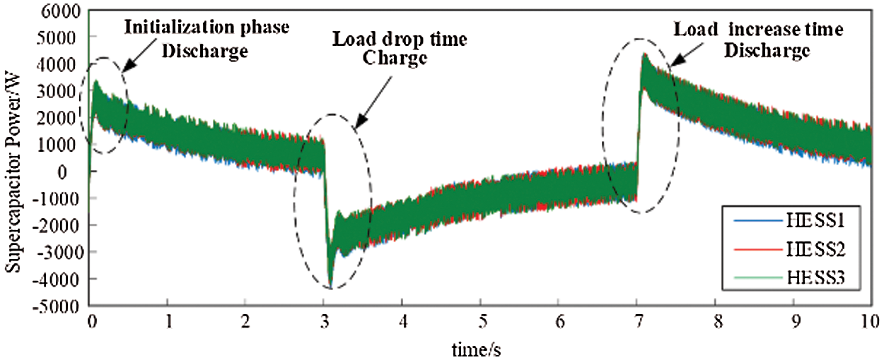
Figure 7: Supercapacitor output power
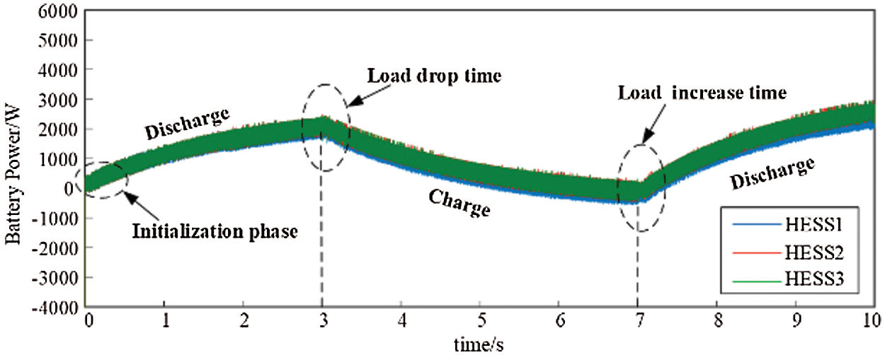
Figure 8: Battery output power
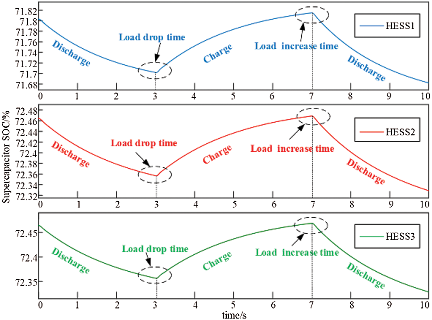
Figure 9: Supercapacitor SOC
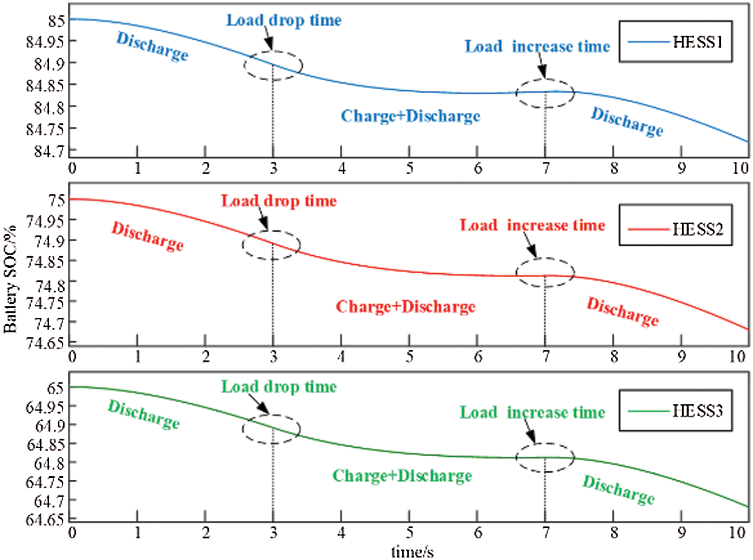
Figure 10: Battery SOC
It can be concluded from the above analysis that the distributed cooperative control can reduce the influence of line impedance on the DC bus voltage, ensure the DC bus voltage to be stable at the desired voltage value, and keep the output current of each HESS consistent.
4.2 Adaptive Event Trigger Simulation Verification
Based on distributed cooperative control, an adaptive event triggering mechanism with variable trigger parameters is introduced and compared with the one with constant trigger parameters.
Fig. 11 shows the variable change process under the control of adaptive trigger parameters of voltage, wherein (a) is the change curve of three groups of HESS trigger parameters, and (b) is the sampling point at the trigger moment. It can be seen that the value of the trigger parameter is smaller than its initial value, verifying the correctness of the range of trigger parameter values in Section 3.
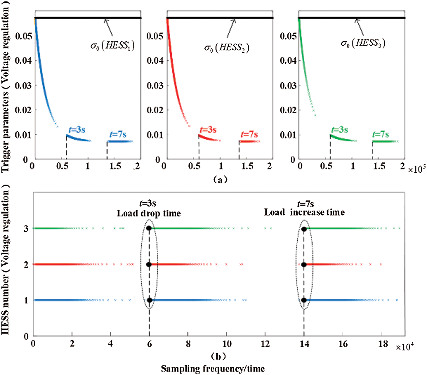
Figure 11: Adaptive event trigger control of voltage
Combined with Figs. 7 and 8, it can be concluded that in the system startup stage, HESS output power increases gradually, corresponding triggering time interval decreases, triggering parameters also decrease, and triggering frequency increases, until DC bus voltage reaches steady-state, triggering frequency decreases, and control signal basically remains unchanged. Fig. 12 shows the variable change process under the adaptive trigger parameter control of current, and the working process is similar to Fig. 11.
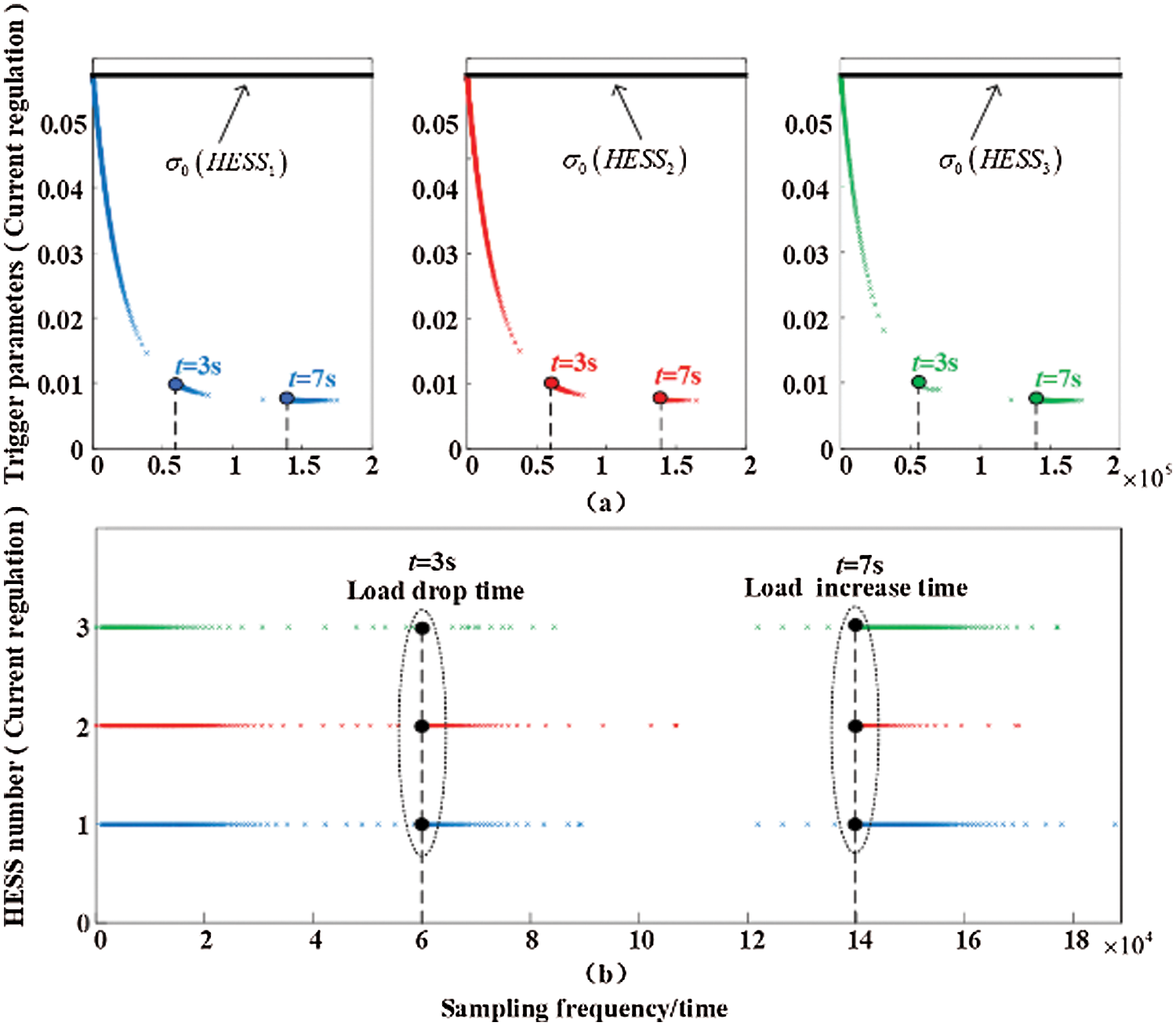
Figure 12: Adaptive event trigger control of current
Fig. 13 shows the ei variation curves of the three groups of HESS state measurement errors. It can be seen that the measurement errors gradually decrease. Combined with Fig. 13, it can be seen that the triggering frequency of corresponding events also decreases.
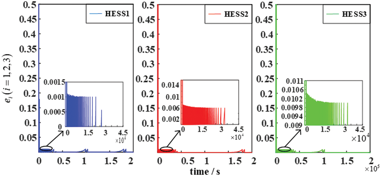
Figure 13: ei change curve
Contrast Figs. 11b and 14, 12b and 15 it can be seen that at system startup phase, the adaptive parameters than fixed trigger triggering frequency trigger is higher, the time needed for steady-state shorter, and the system steady-state phase, basic not trigger event triggered adaptive parameter, and fixed trigger parameters in steady state will trigger events, In the steady state, the number of triggering is higher than that of adaptive event triggering, which increases the communication burden of the system. In comparison, adaptive event triggering has more advantages.
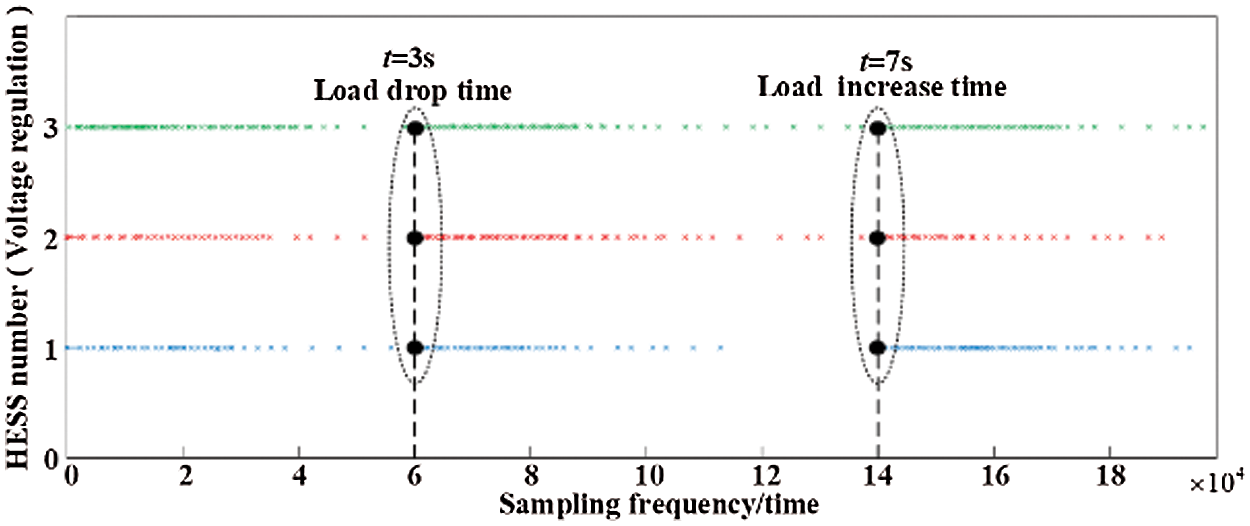
Figure 14: Constant trigger parameter control of voltage
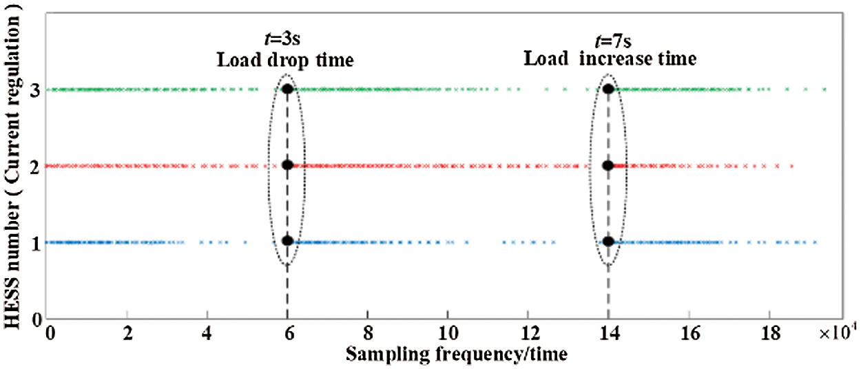
Figure 15: Constant trigger parameter control of current
The research objective in this article is a DC microgrid with several groups of HESS. This article presents an adaptive event-triggered distributed cooperative control strategy in order to cope with increased communication burden and waste of communication resources caused by periodic time triggering, which can be modified in real-time Event trigger interval, keeping limited communication resources. Through the simulation of the DC microgrid system under load disturbance, the DC bus voltage is increased by 0.6% compared with the traditional droop control, the power distribution accuracy of the hybrid energy storage is also significantly improved, and the communication frequency in the steady state of the system is reduced, which verifies that improve the effectiveness of control strategies.
Acknowledgement: The authors would like to thank the editor and the reviewers for their constructive comments which improve the quality of the paper.
Funding Statement: This research was funded by the Natural Science Foundation of Shaanxi Province, Grant No. 2021GY-135 and the Scientific Research Project of Yan'an University, Grant No. YDQ2018-07.
Conflicts of Interest: The authors declare that they have no conflicts of interest to report regarding the present study.
1. Dou, C., Yue, D., Zhang, Z., Ma, K. (2017). MAS-based distributed cooperative control for DC microgrid through switching topology communication network with time-varying delays. IEEE Systems Journal, 13(1), 615–624. DOI 10.1109/JSYST.2017.2726081. [Google Scholar] [CrossRef]
2. Babazadeh-Dizaji, R., Hamzeh, M. (2019). Distributed hierarchical control for optimal power dispatch in multiple DC microgrids. IEEE Systems Journal, 14(1), 1015–1023. DOI 10.1109/JSYST.4267003. [Google Scholar] [CrossRef]
3. Mathew, P., Madichetty, S., Mishra, S. (2019). A multilevel distributed hybrid control scheme for islanded DC microgrids. IEEE Systems Journal, 13(4), 4200–4207. DOI 10.1109/JSYST.4267003. [Google Scholar] [CrossRef]
4. Al-Ismail, F. S. (2021). DC microgrid planning, operation, and control: A comprehensive review. IEEE Access, 9, 36154–36172. DOI 10.1109/Access.6287639. [Google Scholar] [CrossRef]
5. Gururaj, M. V., Padhy, N. P. (2017). A novel decentralized coordinated voltage control scheme for distribution system with DC microgrid. IEEE Transactions on Industrial Informatics, 14(5), 1962–1973. DOI 10.1109/TII.2017.2765401. [Google Scholar] [CrossRef]
6. Zhang, W., Xu, Y. (2018). Distributed optimal control for multiple microgrids in a distribution network. IEEE Transactions on Smart Grid, 10(4), 3765–3779. DOI 10.1109/TSG.5165411. [Google Scholar] [CrossRef]
7. Kirakosyan, A., El-Saadany, E. F., El Moursi, M. S., Yazdavar, A. H., Al-Durra, A. (2019). Communication-free current sharing control strategy for DC microgrids and its application for AC/DC hybrid microgrids. IEEE Transactions on Power Systems, 35(1), 140–151. DOI 10.1109/TPWRS.59. [Google Scholar] [CrossRef]
8. Han, Y., Ning, X., Yang, P., Xu, L. (2019). Review of power sharing, voltage restoration and stabilization techniques in hierarchical controlled DC microgrids. IEEE Access, 7, 149202–149223. DOI 10.1109/Access.6287639. [Google Scholar] [CrossRef]
9. Dragičević, T., Lu, X., Vasquez, J. C., Guerrero, J. M. (2015). DC microgrids—Part I: A review of control strategies and stabilization techniques. IEEE Transactions on Power Electronics, 31(7), 4876–4891. DOI 10.1109/TPEL.2015.2478859. [Google Scholar] [CrossRef]
10. Simpson-Porco, J. W., Shafiee, Q., Dörfler, F., Vasquez, J. C., Guerrero, J. M. et al. (2015). Secondary frequency and voltage control of islanded microgrids via distributed averaging. IEEE Transactions on Industrial Electronics, 62(11), 7025–7038. DOI 10.1109/TIE.2015.2436879. [Google Scholar] [CrossRef]
11. Rey, J. M., Rosero, C. X., Velasco, M., Martí, P., Miret, J. et al. (2018). Local frequency restoration for droop-controlled parallel inverters in islanded microgrids. IEEE Transactions on Energy Conversion, 34(3), 1232–1241. DOI 10.1109/TEC.60. [Google Scholar] [CrossRef]
12. Sun, Y., Shi, G., Li, X., Yuan, W., Su, M. et al. (2017). An f-P/Q droop control in cascaded-type microgrid. IEEE Transactions on Power Systems, 33(1), 1136–1138. DOI 10.1109/TPWRS.2017.2752646. [Google Scholar] [CrossRef]
13. Prabhakaran, P., Goyal, Y., Agarwal, V. (2017). A novel communication-based average voltage regulation scheme for a droop controlled DC microgrid. IEEE Transactions on Smart Grid, 10(2), 1250–1258. DOI 10.1109/TSG.5165411. [Google Scholar] [CrossRef]
14. Liu, X. K., He, H., Wang, Y. W., Xu, Q., Guo, F. (2018). Distributed hybrid secondary control for a DC microgrid via discrete-time interaction. IEEE Transactions on Energy Conversion, 33(4), 1865–1875. DOI 10.1109/TEC.2018.2850279. [Google Scholar] [CrossRef]
15. Guerrero, J. M., Vasquez, J. C., Matas, J., de Vicuña, L. G., Castilla, M. (2010). Hierarchical control of droop-controlled AC and DC microgrids—A general approach toward standardization. IEEE Transactions on Industrial Electronics, 58(1), 158–172. DOI 10.1109/TIE.2010.2066534. [Google Scholar] [CrossRef]
16. Feng, X., Li, Q., Wang, K. (2020). Waste plastic triboelectric nanogenerators using recycled plastic bags for power generation. ACS Applied Materials & Interfaces, 13(1), 400–410. DOI 10.1021/acsami.0c16489. [Google Scholar] [CrossRef]
17. Feng, X., Zhang, Y., Kang, L., Wang, L., Duan, C. et al. (2021). Integrated energy storage system based on triboelectric nanogenerator in electronic devices. Frontiers of Chemical Science and Engineering, 15(2), 238–250. DOI 10.1007/s11705-020-1956-3. [Google Scholar] [CrossRef]
18. Hua, Y., Wang, N., Zhao, K. (2021). Simultaneous unknown input and state estimation for the linear system with a rank-deficient distribution matrix. Mathematical Problems in Engineering, 2021(12), 1–11. DOI 10.1155/2021/6693690. [Google Scholar] [CrossRef]
19. Liu, C., Li, Q., Wang, K. (2021). State-of-charge estimation and remaining useful life prediction of supercapacitors. Renewable and Sustainable Energy Reviews, 150, 111408. DOI 10.1016/j.rser.2021.111408. [Google Scholar] [CrossRef]
20. Wang, K., Liu, C., Sun, J., Zhao, K., Wang, L. et al. (2021). State of charge estimation of composite energy storage systems with supercapacitors and lithium batteries. Complexity, 2021, 1–15. DOI 10.1155/2021/8816250. [Google Scholar] [CrossRef]
21. Meng, W., Wang, X., Liu, S. (2016). Distributed load sharing of an inverter-based microgrid with reduced communication. IEEE Transactions on Smart Grid, 9(2), 1354–1364. DOI 10.1109/TSG.2016.2587685. [Google Scholar] [CrossRef]
22. Yoo, H. J., Nguyen, T. T., Kim, H. M. (2019). Consensus-based distributed coordination control of hybrid AC/DC microgrids. IEEE Transactions on Sustainable Energy, 11(2), 629–639. DOI 10.1109/TSTE.5165391. [Google Scholar] [CrossRef]
23. Zhang, B., Dou, C., Yue, D., Zhang, Z. (2018). Response hierarchical control strategy of communication data disturbance in micro-grid under the concept of cyber physical system. IET Generation, Transmission & Distribution, 12(21), 5867–5878. DOI 10.1049/iet-gtd.2018.5356. [Google Scholar] [CrossRef]
24. Peng, C., Sun, H., Yang, M., Wang, Y. L. (2019). A survey on security communication and control for smart grids under malicious cyber attacks. IEEE Transactions on Systems, Man, and Cybernetics: Systems, 49(8), 1554–1569. DOI 10.1109/TSMC.6221021. [Google Scholar] [CrossRef]
25. Ding, L., Yin, G. Y., Zheng, W. X., Han, Q. L. (2018). Distributed energy management for smart grids with an event-triggered communication scheme. IEEE Transactions on Control Systems Technology, 27(5), 1950–1961. DOI 10.1109/TCST.87. [Google Scholar] [CrossRef]
26. Dou, C. X., Liu, B., Guerrero, J. M. (2014). Event-triggered hybrid control based on multi-agent system for microgrids. IET Generation, Transmission & Distribution, 8(12), 1987–1997. DOI 10.1049/iet-gtd.2013.0869. [Google Scholar] [CrossRef]
27. Pullaguram, D., Mishra, S., Senroy, N. (2018). Event-triggered communication based distributed control scheme for DC microgrid. IEEE Transactions on Power Systems, 33(5), 5583–5593. DOI 10.1109/TPWRS.59. [Google Scholar] [CrossRef]
28. Han, R., Meng, L., Guerrero, J. M., Vasquez, J. C. (2017). Distributed nonlinear control with event-triggered communication to achieve current-sharing and voltage regulation in DC microgrids. IEEE Transactions on Power Electronics, 33(7), 6416–6433. DOI 10.1109/TPEL.2017.2749518. [Google Scholar] [CrossRef]
29. Guo, F., Wang, L., Wen, C., Zhang, D., Xu, Q. (2019). Distributed voltage restoration and current sharing control in islanded DC microgrid systems without continuous communication. IEEE Transactions on Industrial Electronics, 67(4), 3043–3053. DOI 10.1109/TIE.41. [Google Scholar] [CrossRef]
30. Qian, T., Liu, Y., Zhang, W., Tang, W., Shahidehpour, M. (2019). Event-triggered updating method in centralized and distributed secondary controls for islanded microgrid restoration. IEEE Transactions on Smart Grid, 11(2), 1387–1395. DOI 10.1109/TSG.5165411. [Google Scholar] [CrossRef]
31. Zhang, B., Dou, C., Yue, D., Zhang, Z., Zhang, T. (2019). A packet loss-dependent event-triggered cyber-physical cooperative control strategy for islanded microgrid. IEEE Transactions on Cybernetics, 51(1), 267–282. DOI 10.1109/TCYB.2019.2954181. [Google Scholar] [CrossRef]
32. Yan, H., Han, J., Zhang, H., Zhan, X., Wang, Y. (2020). Adaptive event-triggered predictive control for finite time microgrid. IEEE Transactions on Circuits and Systems I: Regular Papers, 67(3), 1035–1044. DOI 10.1109/TCSI.8919. [Google Scholar] [CrossRef]
33. Chen, M., Xiao, X., Guerrero, J. M. (2017). Secondary restoration control of islanded microgrids with a decentralized event-triggered strategy. IEEE Transactions on Industrial Informatics, 14(9), 3870–3880. DOI 10.1109/TII.9424. [Google Scholar] [CrossRef]
34. Wang, Y., Deng, C., Liu, D., Xu, Y., Dai, J. (2020). Unified real power sharing of generator and storage in islanded microgrid via distributed dynamic event-triggered control. IEEE Transactions on Power Systems, 36(3), 1713–1724. DOI 10.1109/TPWRS.2020.3039530. [Google Scholar] [CrossRef]
 | This work is licensed under a Creative Commons Attribution 4.0 International License, which permits unrestricted use, distribution, and reproduction in any medium, provided the original work is properly cited. |