| Computer Modeling in Engineering & Sciences |
DOI: 10.32604/cmes.2022.019528
REVIEW
Review of Numerical Simulation of TGO Growth in Thermal Barrier Coatings
1Aero Engine Academy of China, Aero Engine (Group) Corporation of China, Beijing, 101304, China
2Institute for Aero Engine, Tsinghua University, Beijing, 100084, China
*Corresponding Authors: Fulei Jing. Email: jingfulei@163.com; Junjie Yang. Email: yangjunjie@tsinghua.edu.cn
Received: 01 November 2021; Accepted: 31 December 2021
Abstract: Thermally grown oxide (TGO) is a critical factor for the service life of thermal barrier coatings (TBC). Numerical simulations of the growth process of TGO have become an effective means of comprehensively understanding the progressive damage of the TBC system. At present, technologies of numerical simulation to TGO growth include two categories: coupled chemical-mechanical methods and mechanical equivalent methods. The former is based on the diffusion analysis of oxidizing elements, which can describe the influence of bond coat (BC) consumption and phase transformation in the growth process of TGO on the mechanical behavior of each layer of TBC, and has high accuracy for the thickness evolution of TGO, but they cannot describe the lateral growth of TGO and the rumpling phenomenon induced. The latter focuses on describing the final stress and strain state after the growth of a specific TGO rather than the complete growth processes of TGO. Based on the measured TGO thickness growth curve, simulations of thickening and lateral growth can be achieved by directly applying anisotropic volumetric strain to oxidized elements and switching elements properties from the BC to the TGO.
Keywords: Thermal grown oxide (TGO); numerical simulation; thermal barriers coatings (TBC); finite element method; lateral growth
Thermal Barrier Coating (TBC) is effective thermal protection widely used in the gas turbine to protect air-cooled blades or vanes exposed to high temperatures environment [1,2]. It provides thermal insulation and oxidation resistance to the superalloy substrate from the combustion gas, which can effectively improve the operating temperature of the turbine and reduce the requirement of internal cooling air to enhance the engine performance. On the other hand, TBC can also extend their in-service durability by lowering the temperature of superalloy substrate surface [3–14]. The effect of TBC is sketched in Fig. 1.
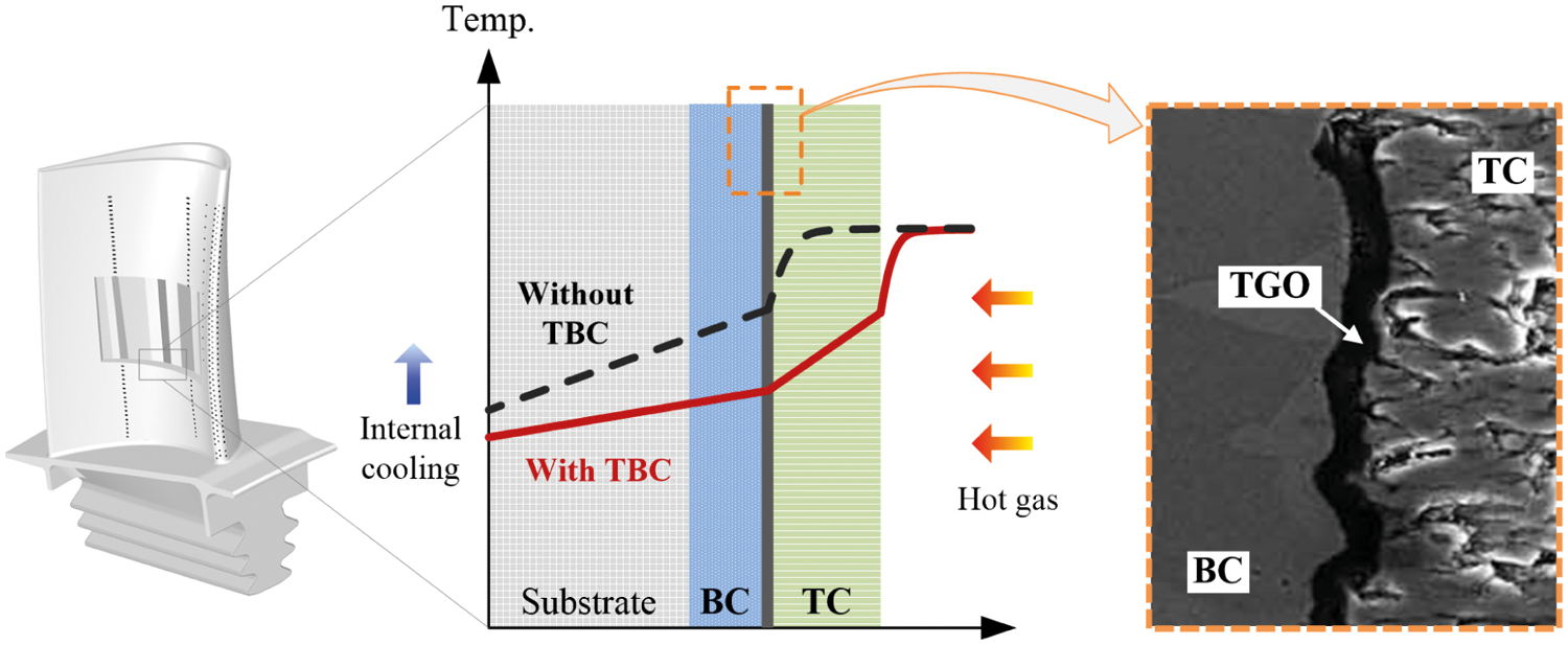
Figure 1: Typical TBC system in turbine blade [15,16]
A typical TBC system consists of a ceramic topcoat (TC) with low thermal conductivity and an Al-rich and oxidation-resistant metallic bond coat (BC) [15–17]. In a long-term high-temperature environment, oxygen can penetrate through the TC and oxidize with metal elements such as Al and Cr in the BC to form an oxide film, that is, the thermally grown oxide (TGO) [18,19], as shown in Fig. 1. The main component of TGO is Al2O3, and its thickness is much small, generally less than 10
TGO plays the role of oxygen barrier due to very dense that is difficult for oxygen to penetrate further, preventing the substrate from being oxidized and corroded. However, the coefficient of thermal expansion (CTE) of TGO is less than that of others, which is detrimental to the internal mechanical compatibility of the TBC system [28–39]. Studies have demonstrated that thermal growth of TGO dominated by Al2O3 at the ceramic-metal interface is one of the dominant damage mechanisms that affect the life of the TBC system, especially for aero engines and industrial gas turbines [40,41]. Thus, TGO is the weakest link that restricts the service life of TBC [3,42–53].
The growth of TGO is essentially a complex dynamic process coupled with chemistry and mechanics, generally including internal oxidation, grain boundary oxidation, and external oxidation. Internal oxidation is that oxygen anions diffuse inward through the TC and react with Al cations from the BC at the TGO-BC interface. Grain boundary oxidation is that Al cations react with oxygen at the grain boundaries within the TGO, and external oxidation is that Al cations in TGO subsequently diffuse outward and react with oxygen anions at the TC-TGO interface [54–60]. Internal oxidation is accompanied by unrecoverable volume expansion, and grain boundary oxidation induces the lateral extension of TGO. Both are restricted by surrounding materials, resulting in additional growth stress [55,61]. Due to the multilayer structure of the TBC system, the existing non-destructive testing technology cannot directly measure the interface morphology under the TC layer [62–78]. Numerical simulation of the growth process of TGO has become an effective means to recognize the progressive damage of the TBC system. Therefore, the TGO growth numerical simulation methods are investigated and summarized in recent years herein to provide references for the approaching TBC research.
2 Coupled Chemical-Mechanical Methods
2.1 A Coupled Framework of Oxidation-Constitutive
In 2001, Busso et al. [54] proposed a coupled oxidation-constitutive method for a plasma-sprayed thermal barrier coating (PS-TBC) system, which can describe the influence of the phase transformation caused by the local oxidation process on the constitutive behavior of the BC. The growth rate of TGO is mainly affected by the internal oxidation that the inward diffusion of oxygen along the grain boundary towards the TGO-BC interface, and by the external oxidation that the outward diffusion of Al cations along the alumina particle boundary reacting with oxygen anions at the interface of TGO-TC.
For the BC made of MCrAlY material, the main oxidation reaction is the internal oxidation reaction in
Thus, the average volumetric strain caused by the internal oxidation is
where
Once the material at some point starts to be oxidized, the total expansion strain of TGO inward growth is controlled by the volume fraction of Al2O3 generated by the main oxidation reaction. Suppose BC is composed of an oxidation-resistant phase (Phase 1) and an oxidation-prone phase (Phase 2). With the start of oxidation, a very thin layer of internal oxidation zone (IOZ) is formed at the ceramic-metal interface, where an internal growth oxide co-exists with Phase 1 and Phase 2. The IOZ is a thin transition zone between BC and TGO that moves inward as the oxidation progresses. Due to the inter-diffusion process driven by the concentration gradient from one side of the IOZ to the other, the local oxide volume fraction is increased from approximately
Based on the known volumetric fractions of each material phase before, during and after oxidation, a constitutive framework based on a self-consistent scheme was established to describe the mechanical behavior of an equivalent homogeneous solid in the IOZ. The inelastic deformation rate tensor can be decomposed into the average inelastic deformation rate term caused by slip and the irreversible phase transformation deformation rate term characterizing the metal phase oxidation, assuming that which is controlled by the rate of change of the internal oxidation volume fraction. If the local oxygen concentration of each material point is greater than or equal to the critical value, then this point starts to be oxidized.
For the external oxidation, to improve the calculation efficiency, it is assumed that the oxide is generated on the original TGO instantaneously and its constitutive behavior is thermo-elastic, and that the volumetric strain related to the external oxidation is zero in the plane of the TGO-ceramic interface and is maximum in the out-of-plane direction. In fact, Al cations will also react with oxygen at the internal interface of TGO, causing TGO to grow laterally at a low local defect density. However, Busso's model did not consider this situation to simplify the calculation.
The oxidation kinetics equation for the growth of the TGO thickness under isothermal oxidation was established based on the Arrhenius's equation [79], as follows:
where
Furthermore, Busso et al. [80,81] applied the coupled diffusion-constitutive framework to EB-PVD TBC system. For the Ni(Pt)Al diffusion aluminide BC, the internal oxidation reaction of
Then the average volumetric strain associated with the primary oxidation reaction can be obtained,
In Busso's research,
Hille et al. [48] used the diffusion-reaction equation to simulate the oxidation of Al in BC as follows:
where c is the free oxygen concentration, n is the TGO volume fraction between 0 (pure BC) to 1 (pure TGO),
The model describes the diffusion of oxygen to Al in BC, and the sink term on the right side of the equation relates the consumption of free oxygen to the formation of TGO, i.e., Al2O3. Both the reaction rate and the growth kinetics depend on the availability of reactants. By reasonably selecting the oxidation rate parameters, it can be ensured the calculated TGO morphology evolution can be consistent with the experimental observation results. In essential, this model considers that there is an oxidation zone, that is, a thin conversion layer (mixed TGO and BC) where the volumetric fraction of the oxide is between the TGO volume fraction from
Assuming that the initial TGO thickness is
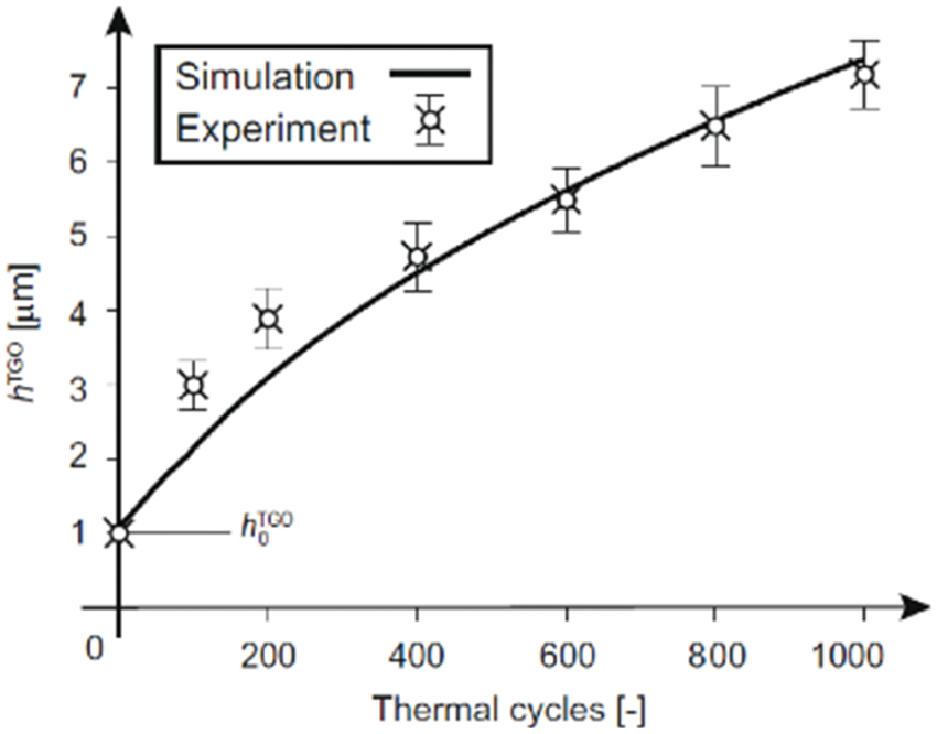
Figure 2: Comparison of TGO thickness evolution calculated and results measured in tests [44]
In fact, the predicted results by the above models reflect the average thicknesses of the growth of the TGO. Shen et al. [83] also used the above diffusion-reaction Eq. (6) to describe the internal oxidation process. The method considers there is a mixed zone between pure BC and pure TGO, where the volumetric fraction of TGO is between 0 and 1. The Lame constant can be obtained through the volumetric weighted of each component [84,85]. The stress and deformation during the TGO growth are described by introducing the finite deformation theory, and the Jacobian determinant of the growth deformation gradient is used to represent the volume ratio of stress-free state after and before oxidation. This method can describe the phenomenon of uneven thickness of TGO between peaks and valleys, as shown in Fig. 3.
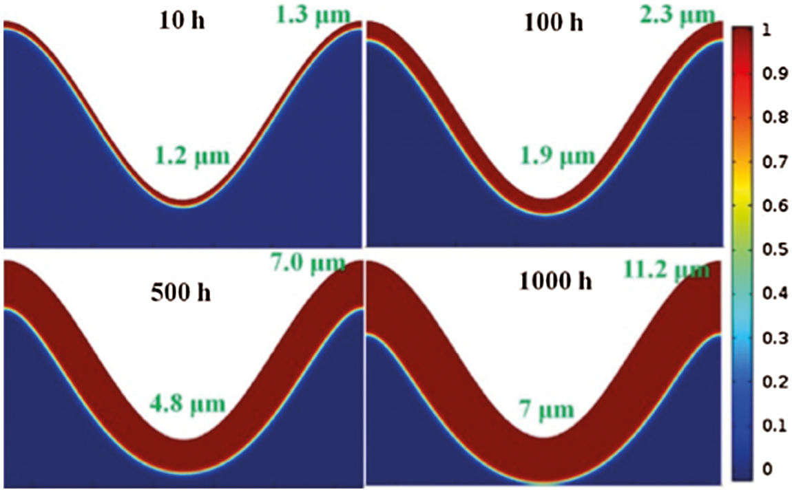
Figure 3: Evolution of TGO morphology with oxidation exposure time [83]
However, experimental observations show that there is a clear boundary between the BC and the TGO, which is inconsistent with the assumption in the coupled diffusion-constitutive framework that in the IOZ or BC-TGO mixed zone the initial phase of the alloy co-exists with the oxide. To handle this problem, Caliez et al. [86] assumed that the element has been oxidized when the chemical activity of the material in BC reaches a critical value, its properties are switched instantaneously, and the volume expansion is applied simultaneously. It implies that the state variables need to be reset before the mechanical equilibrium calculation. This study adopts the weak coupled strategy of oxygen diffusion from the outside to the TGO/BC interface and aluminum diffusion from the BC to the TGO/TC interface to simulate the oxidation process, the flowchart is shown in Fig. 4. In the calculation, the nodal displacement field obtained by the mechanical sub-problem is transferred to the diffusion sub-problem, which is used to consider the geometric evolution caused by the volume expansion.
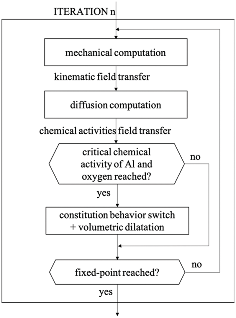
Figure 4: Weak coupled scheme flowchart [86]
To calculate the oxidation kinetic, global diffusivities have to be fitted by an inverse method, considering the stoichiometric mass concentration in the critical chemical activity assessment. The experimental observation results show that the anion growth mechanism is dominant, and the mesh size has no effect on the results of computed kinetic if the thickness of TGO grows at least one row within a time increment step.
It should be noted that the inverse method or iterative process is required to obtain some parameters to maintain consistency with the experimental results when the local shape of the TGO is established using a sine wave to assess the growth stress in the above methods. Gupta et al. [87] established a two-dimensional TGO growth model based on the diffusion-reaction equation of aluminum and oxygen, and effectively evaluate the stress behavior and life of TBC using the TGO profiles extracted at different TGO growth stages in the stress analysis model. To simplification some assumptions of the model are adapted including:
• TGO growth is occurring only during the dwell phase of the thermal cycle test;
• BC is mainly composed of aluminum, TGO is pure Al2O3, and other oxides are neglected;
• The rate of Al2O3 formation is much higher than the rate of the diffusion of the Al and oxygen;
• The consumption of Al in BC cannot be considered during exposure;
• Only the inward growth of TGO is considered in the model;
• The oxygen diffusion rate in TC is very high because ZrO2 is transparent to oxygen flow.
Based on these assumptions, a TGO growth model based on diffusion is established using the computational fluid dynamics (CFD) method in ANSYS Fluent. Two solid domains are defined in the TBC system, namely a stationary gas area containing oxygen (representing TC) and a solid aluminum region (representing BC). The system includes two initial solid scalar quantities, namely oxygen and aluminum diffused in the solid region, and the third solid scalar quantity is Al2O3 formed during the simulation. Each of these scalar concentrations
where
Assuming that the element concentration threshold value in BC is
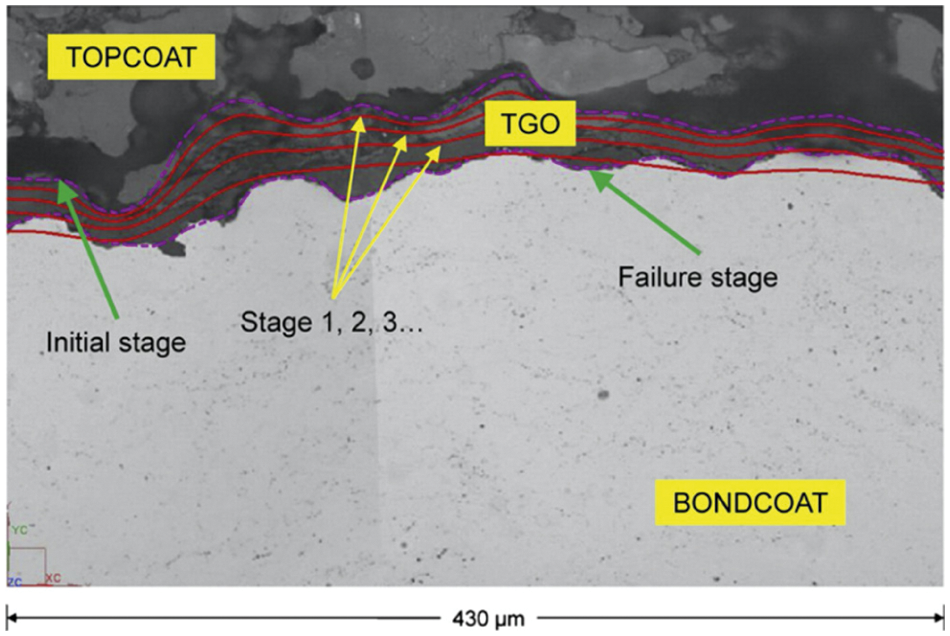
Figure 5: TGO profile obtained from the TGO growth model plotted over microstructure image at failure indicated by solid lines for a sample [87]
2.2 A Coupled Framework of Microstructure-Mechanics
Hermosilla et al. [88] proposed a sequential coupled microstructure-mechanical FE analysis method. In the BC constitutive model, the effects of microstructure degradation and oxidation at high temperatures are considered. The BC material is regarded as a multiphase mixture, so some physical properties, such as elastic modulus and thermal expansion coefficients, can be obtained based on Eshelby's inclusion technique. And other parameters, including the creep strain rate, oxidation reaction
where
The PBRs of
The growth equation of TGO thickness is as follows:
where these parameters are the same as those in the aforementioned models.
The coupled microstructure-mechanics analysis process is shown in Fig. 6a. A 1D finite difference model is used to perform microstructure calculations to generate tables of phase proportions at each depth into the coating and the substrate as a function of time, temperature and substrate composition. Then the results of the 1D model are mapped to the 2D axisymmetric grid of the FE model, as shown in Fig. 6b, where interpolation is required due to the difference in grid discretization. The volume fraction interpolation results of each phase in BC are written into the ABAQUS *.fil file as field variables, while it is single-phase Al2O3 in TGO. The field variable file is read by the ABAQUS solver and called in the user subroutine UMAT defining the mechanical behavior of BC and TGO.
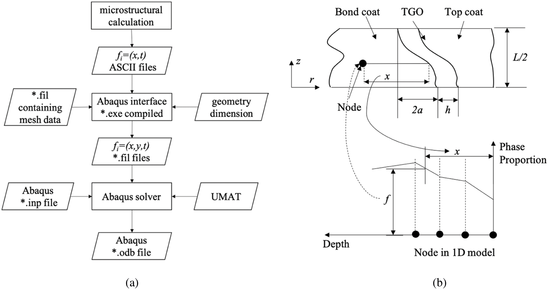
Figure 6: The coupled microstructural–mechanical framework in [88]. (a) The flowchart in the sequentially coupled microstructural–mechanical analysis. (b) The linear interpolation scheme to map the microstructural data from the 1D FD model to the 2D FE mesh. The phase proportions,
The material model of each layer is defined as follows:
• The substrate is IN-713LC, which is defined via temperature-related tables of constitutive properties in the ABAQUS input file. Although the microstructure evolution simulation of the substrate-coating interface is carried out in the 1D finite-difference model, the influence of the local interdiffusion between the BC and the substrate on the performance of the substrate is ignored in the FE model.
• BC and TGO are treated as a single region in the FE model whose performances are described by the UMAT subroutine as a self-consistent model. The constitutive model simulates the performance evolving of BC with the microstructure changes, or a single-phase Al2O3 representing the TGO. This method can describe the moving BC/TGO interface when the performance of elements changes from the multiphase BC material to the TGO. For a given BC element, oxidation occurs instantaneously, and the BC and TGO phases do not exist at the same time in an element. TGO growth simulation is performed by changing the BC element adjacent to the TGO to pure Al2O3 and applying volume expansion based on the PBR of the oxidation reaction.
• The properties of the TC are defined via temperature-related tables in the ABAQUS input file, like the substrate.
Based on a similar method, Kyaw et al. [89] described the influence of microstructure evolutions of the BC and the sintering of the TC using UMAT subroutines. To obtain the performance of the BC material, the volume fraction of each composition phase of the BC is calculated in advance through the diffusion model. In addition, the amount of BC oxidation and the caused volume expansion need to be considered in UMAT. The empirical model of the TGO thickness growth proposed by Meier et al. [79] is used to calculate the thickness of BC oxidation at each time step.
In 2017, Kyaw et al. [90] applied the above method to the thermo-mechanical stress analysis of the TBC with the three-dimensional interface, in which the continuous change of the BC composition ratio caused by the oxidation during the heating and dwell time or by the inter-diffusion at the substrate/BC interface can be evaluated through the finite difference (FD) and thermodynamic calculation. The atom flux of aluminum at the BC/TGO interface is calculated through the empirical oxidation equation. According to the predicted proportion of intermetallic compounds, Eshelby's inclusion technique and pure BC phase material properties, a constitutive model including elasticity, creep, coefficients of thermal expansion for the aggregate properties of the BC is established.
To realize the transformation of the one-dimensional phase proportion data into the three-dimensional FE model, BC is modeled with a multi-layer structure, as shown in Fig. 7. The thickness of each layer is predefined in the pre-processing stage, and material points calculating the BC properties are assumed to be located in the middle of each layer. According to the empirically derived oxidation law [79], the BC layer is transformed into TGO, and the growth strain based on
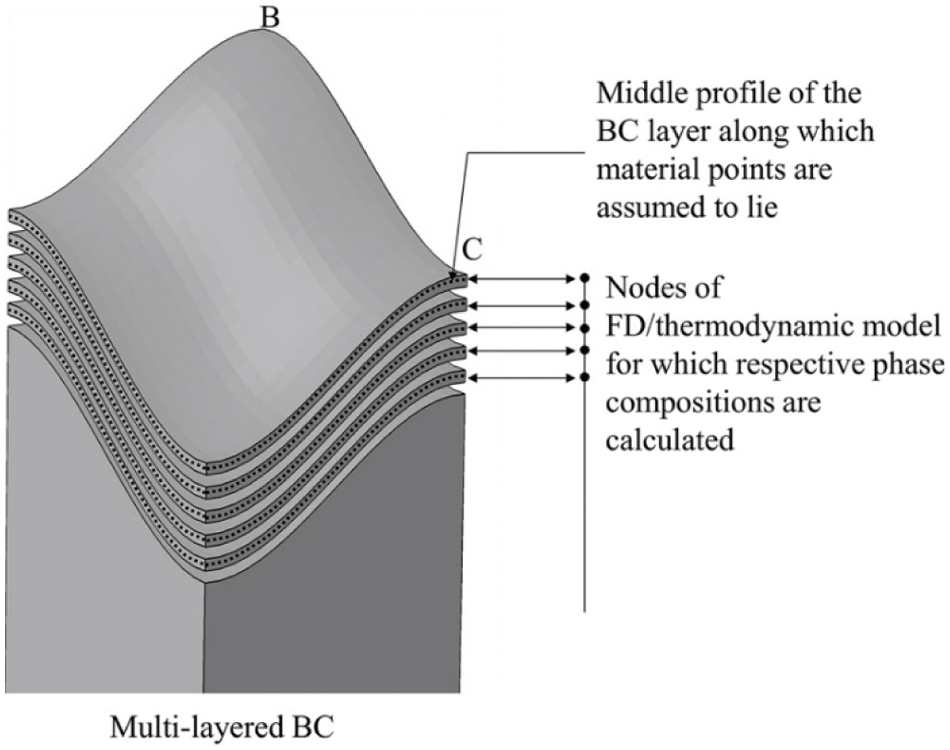
Figure 7: BC multi-layer structure model, used to realize one-dimensional FE model [86]
Totally, coupled chemical-mechanical methods, including the coupled oxidation-constitutive framework and the coupled microstructure-mechanical framework, can thoroughly describe the TGO thickening process, but the influence of the lateral growth of TGO forming on the internal grain boundaries cannot be considered. The obtained interface roughness basically does not change with thermal cycles, so these methods cannot simulate the TGO rumpling [92–107] and stress redistribution that occurred in the thermal fatigue test. However, the thickness evolution of TGO predicted according to these methods is consistent with experimental observations, indicating that they can be used to predict the average thickness of TGO growth.
3 Mechanical Equivalent Methods
3.1 TGO Growth Simulation by Element Volumetric Swelling
Numerical analysis and experiments have confirmed that the BC surface morphology changes during cyclic oxidation, driven by the mismatch strain caused by the thermal expansion misfit between the TGO and the BC during cooling and by the strain associated with the oxide growth at the high temperature. To deal with the above-mentioned situation, Karlsson et al. [42,108] established a numerical model of TGO displacement instability, in which the amplitude of the concave and convex imperfection gradually increases with thermal cycling. During the simulation of the oxidation process, both the lateral elongation and the thickness increase in the TGO are considered based on the anisotropic growth equation. In each cycle, the growth strain component
Four-node axisymmetric bilinear elements were used for the large deformation analysis of BC and TGO in ABAQUS. The in-plane strain component,
where
The morphological changes of BC and TGO with
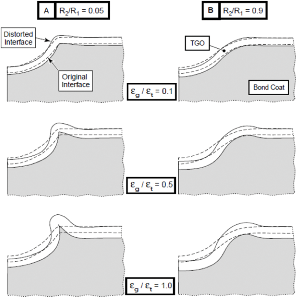
Figure 8: Morphology changes of BC and TGO [104]
Rosler et al. [120] assume that the growth rate
where
Based on a method similar to that of Karlsson et al. [42,108], assuming that the ratio of the strain rate in the thickness direction to that in the lateral growth direction is 10, that is
Similarly, considering the thickening and lateral growth of TGO at the same time, Seiler et al. [122] conducted a multi-scale failure analysis to TBC system in ABAQUS, in which the first-order axisymmetric four-node hybrid elements were used to establish the microscopic model to describe the formation of initial delamination, and the four-node hybrid generalized plane strain elements were used to establish a segmented crack model to analyze the interaction between delamination and segmentation crack on the mesoscale, as shown in Figs. 9a and 9b, respectively.
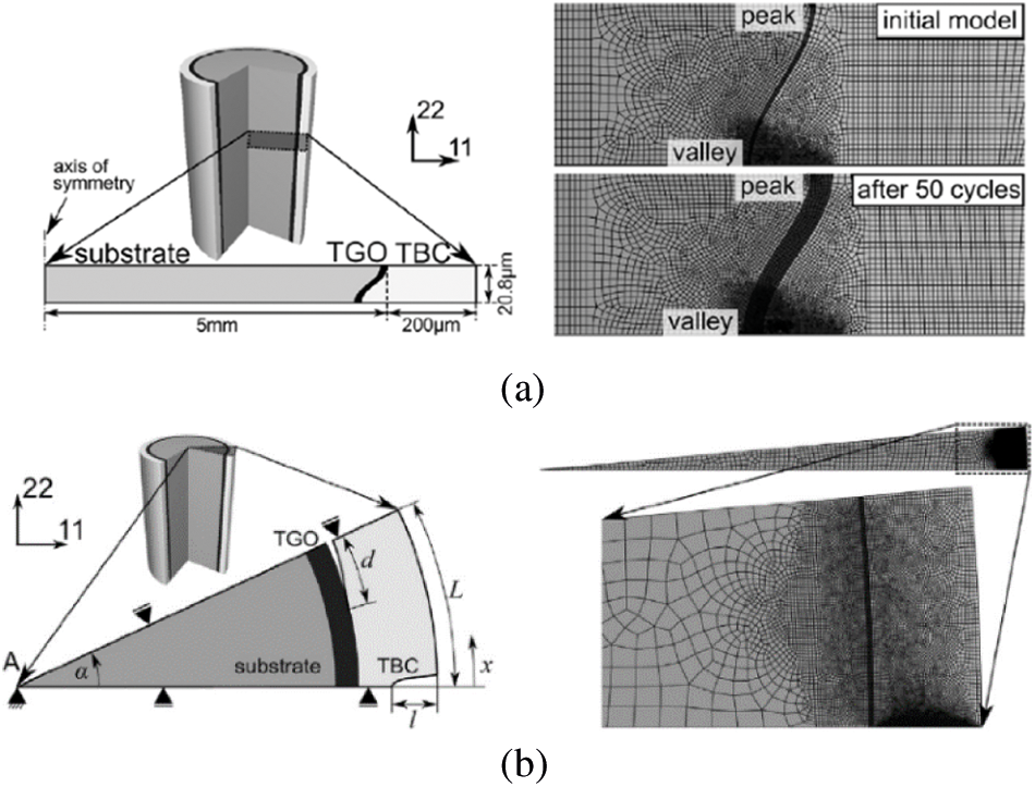
Figure 9: (a) Microscopic model with the first-order axisymmetric four node hybrid elements (b) Segmented crack model with the four-node hybrid generalized plane strain element [119]
Ebrahimi et al. [123] simulated the oxidation process in the FE model used by the Echsler equation as follows:
where
The FE model for simulating TGO growth under the thermal fatigue load in ABAQUS is shown in Fig. 10. The initial thickness of TGO,
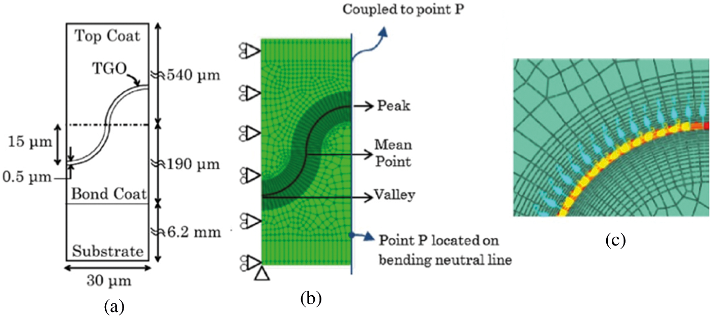
Figure 10: (a) The thickness of each layer in TBC system, (b) FE model and (c) material orientation in TGO [120]
Jiang et al. [125] simulated the growth of TGO on the BC surface and the growth of internal oxides in the BC, both accompanied by the volumetric swelling. The growth of the TGO is mainly controlled by the internal diffusion of oxygen described by the phenomenological equation as follows [126–132]:
where
The thickening of TGO is simulated in ABAQUS, but the influence of the lateral growth of TGO is not considered. The FE model is shown in Fig. 11a, in which the plane strain thermal coupling element (CPEG4T) is used. Similar to the growth of the TGO, the growth of the internal oxide includes two aspects: firstly, internal oxides grow to take the places originally belonging to the BC, which can be modeled by switching the material properties from BC to the internal oxide; secondly, the internal oxides also swell. Due to the lack of relevant experimental data, however, the growth of internal oxide is only regarded as the volume swelling in the FE analysis. Considering that the internal oxidation mechanism within BC is similar to the formation of interfacial TGO on the surface of BC, it is assumed that the relationship between internal oxide volume expansion and dwell time can also be characterized by a power function as follows:
where F is the volume fraction of internal oxides,
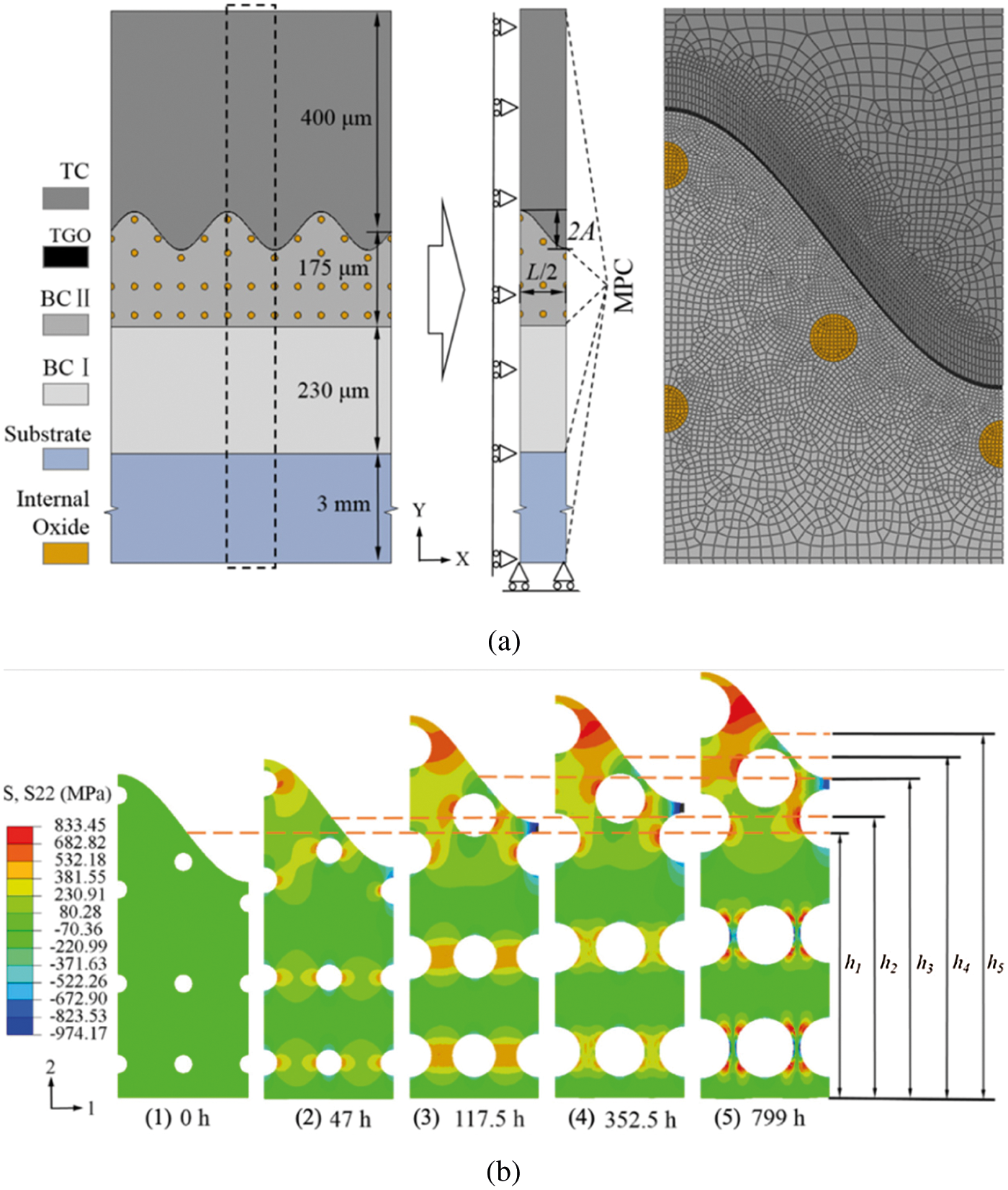
Figure 11: (a) Geometry and FE mesh of the two-dimensional FE model of TBC with double-layered BC and (b) the out-of-plane stress distributions of BC II layer at room temperature after different thermal exposure times [125]
Cen et al. [133] used the following parabolic equation to describe the TGO thickening:
where
The oxidation time is from
Then, the oxidation strain is as follows:
Therefore, the volumetric strain rate of the TGO can be calculated. It should be noted that the growth of the TGO is anisotropic, and the strain rate in the thickness direction is about 10 times that in the lateral direction, which is consistent with the previous assumption [120]. A half-period axisymmetric FE model for a cylinder structure with the TBC system is modeled, and the TGO profile at the end of the thermal cycle is shown in Fig. 12. It can be seen that the values of the TGO thickness both at the valley and at the peak are more than the calculated results obtained according to the TGO growth Eq. (18),
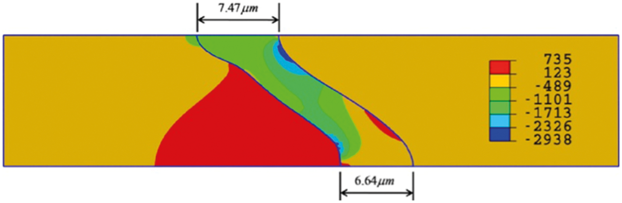
Figure 12: Radial stress distribution at the end of thermal cycle [130]
Nayebashaee et al. [134] simulated TGO growth through the swelling option in ABAQUS. The method assumes that TGO grows uniformly in the thickness direction and the lateral direction, and the ratio of growth rate in two directions to that in the lateral direction is 10. In the case of anisotropic growth, the oxidation step begins with one initial value of TGO thickness, which can make TGO reach a predefined thickness at the end of the step. The growth of TGO abides by the following equation:
where d is the thickness of TGO, t is the oxidation time, and k is the coefficient determined by experiments. The six-node triangular element with generalized plane strain approximation and reduced integration is used for analysis, and a hybrid adaptive meshing is introduced to avoid the divergence or incomplete solution caused by the excessive distortion of the interface with the small meshing region. Fig. 13 shows the
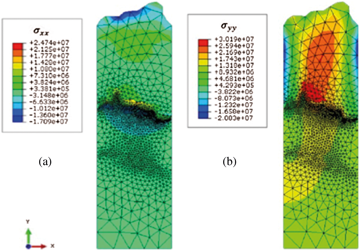
Figure 13: Stress distribution considering the TGO growth [134]
Ranjbar-Far et al. [135] used the Tamman equation to describe the growth of the TGO thickness s and its growth rate
where i is the coordinate axis of the local coordinate system, axis
A FE model with the quadratic six-node triangular elements with generalized plane strain approximation and reduced integration is used for analysis. The results of stress analysis for the sine shape of TGO are shown in Figs. 14a–14c, it can be seen that the tensile stress region at the peak of the BC is developed gradually to the middle of the TC/TGO interface with the thickness increase of TGO, and the compressive stress is observed not only at the valley of the BC but also at the peak of TGO/TC interface. Therefore, the crack may be nuclear and propagate at peak of the BC (mechanism I) or the middle of the TC/TGO interface (mechanism II), then coalesce through the TGO causing the delamination of the system (mechanism III). The stress distribution is in accordance with actual micro-cracks propagations presented in Fig. 14d.
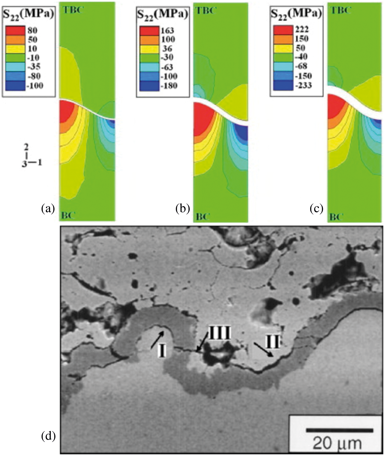
Figure 14: Out-of-plane stresses distribution in the TBC with the sine shape of TGO with
It can be seen from the above results of FE models that elements volumetric swelling is only suitable for the small deformation of the thickness of TGO. These methods do not involve the BC consumption process and simplify the TGO growth as the anisotropic swelling of the volume of oxidized elements. The equivalent thickness direction strain rate is calculated through the measured TGO thickness growth equation. Assuming the lateral growth strain rate is proportional to the strain rate in the thickness direction, the thickening and lateral growth of the TGO can be achieved.
3.2 TGO Growth Simulation by Element Conversion
Based on Karlsson's model, He et al. [136] introduced the effect of large-scale thickening of TGO. Considering that the growth strain of TGO includes a small lateral component
Due to that
Jinnestrand et al. [137] considered that the swelling strain caused by the increased volume during the growth of TGO is related to the stress state. It is assumed that the stress state has the relationship with the swelling strain of TGO as follows:
where P is the hydrostatic pressure,
The growth of TGO is caused by the diffusion of anions or cations. Above
Shen et al. [138] described the growth law of the TGO thickness h using a phenomenological model as follows
where n is the number of thermal cycles,
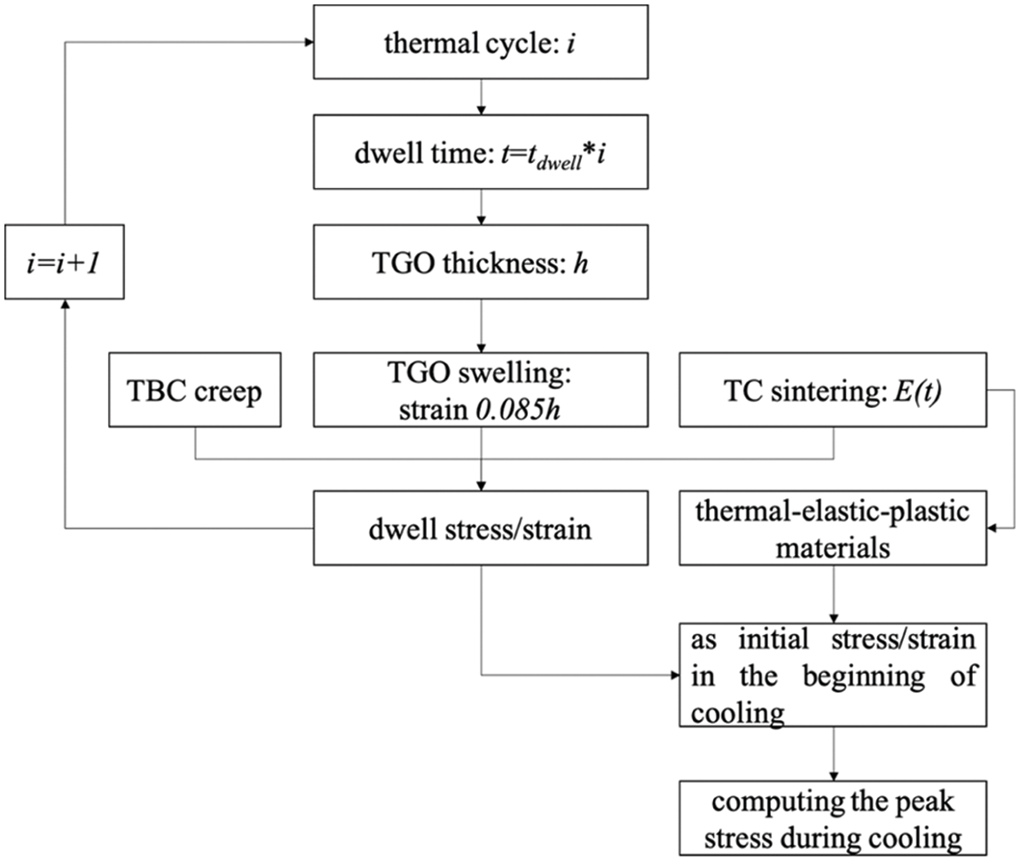
Figure 15: The flow chart of TBC stresses simulation at
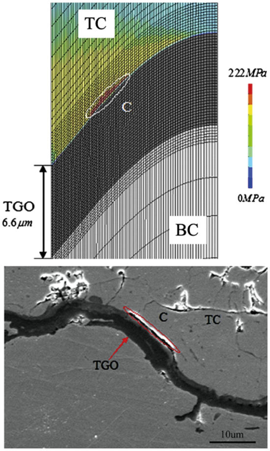
Figure 16: The maximum principal stresses in TC with 900 thermal cycles and crack growth in the similar region C [138]
Busso et al. [140,141] converted the material properties of the element around the TC/BC interface into TGO at an appropriate time to simulate the oxidation process, as shown in Fig. 17. The converted element is determined based on the TGO growth rate curve obtained by the experiment and the distance from the element to the TC/BC interface. The volume swelling caused by oxidation is determined by the PBR and the experimentally obtained ratio for the in-plane and out-of-plane expansions.
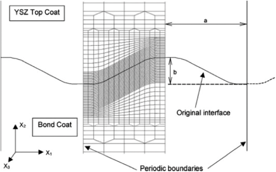
Figure 17: Elements around the interface in the FE model are used to simulate TGO growth [139]
Aiming at the chemical failure caused by the growth of non-protective oxides such as NiCr2O4, Busso et al. [141] used the phenomenological equation of the TGO growth to describe the breakaway oxidation. Supposing after a certain time
where
In fact, the protective oxide is still produced in the TGO valley region during the breakaway oxidation. To speed up the computation process, an equation similar to the wave peak can be used to describe wave valleys as follows:
The TGO thickness in the zone between apexes and valleys can be determined by the linear interpolation. Here, the PBR of protective
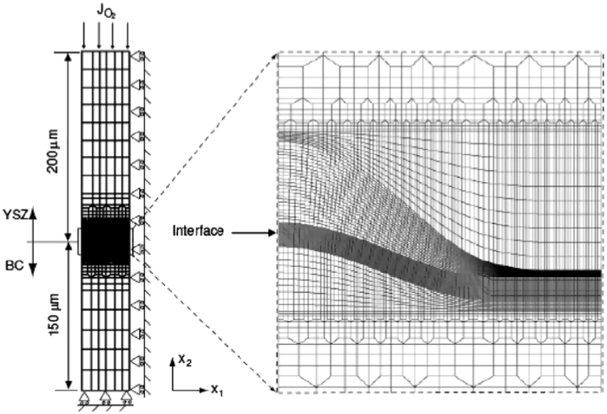
Figure 18: A finite element mesh and the boundary condition with initial thicknesses of the BC and YSZ layers were 50 and 200
Wei et al. [119] considered that the main reason why the TGO growth stress directly calculated through PBR was far greater than the experiment value was a large number of atomic vacancies generated due to the diffusion of elements during the BC oxidation process offset part of the expansion stress. Thus, the volume swelling strain
where
The TGO thickness increment for each thermal cycle can be calculated according to Eq. (31). In the simulation, after each thermal cycle, the material properties of the corresponding elements are converted from the BC to the TGO, at the same time the corresponding thickening strain
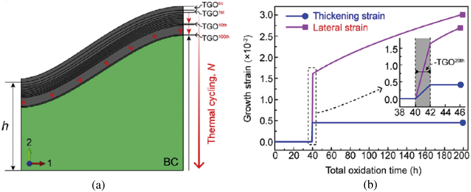
Figure 19: (a) The Schema of TGO growth simulation and (b) the evolution of the oxidative growth strain of the 20th thickened layer with the total oxidation time [119]
The TGO lateral strain rate
where
Fig. 19b shows the evolution of the growing strain in the 20th thickening layer with the total oxidation time. When elements are transformed,
It can be seen that methods of element conversion transform properties of elements in the BC to Al2O3 to simulate the TGO growth, which replaces the complex diffusion model with the measured TGO thickness growth curve or the distance between the material point and the TGO interface as the oxidation criterion of BC elements. Unlike methods of element volumetric swelling, which is only suitable for small changes in the thickness of TGO, the larger-scale thickening of TGO can be achieved by converting the material properties of oxidized elements and simultaneously applying the anisotropic volume expansion strain. However, the achievement of the lateral growth of TGO is as same as that in methods of element volumetric swelling, that is, the lateral growth of TGO is modeled by imposing the lateral volumetric swelling to the whole TGO layer.
• The chemical-mechanical coupling method can directly or indirectly describe the element diffusion, BC consumption, and TGO thickening during the growth of TGO. The oxidation-constitutive coupling framework integrated the diffusion equation into the material constitutive model to achieve the dynamic simulation of the growth process of TGO and the consumption of oxidation in the BC, while the microstructure-mechanics coupling framework can consider the influence of microstructure degradation caused by BC oxidation and phase transformation on the mechanical behavior of materials at high temperatures by treating the BC as a mixture. However, the chemical-mechanical coupling methods are all aimed at the TGO thickening process and do not consider the influence of the lateral growth of TGO caused by grain boundary oxidation. The interface roughness obtained basically cannot evolve with the number of thermal cycles, and cannot simulate the TGO wrinkling and the stress redistribution phenomenon occurring in the thermal fatigue test.
• The mechanical equivalent method cannot describe the complete process of TGO growth, but focuses on the final stress and strain state after the specific TGO growth. The volumetric swelling of TGO elements is to treat TGO growth equivalently as the anisotropic volume expansion of TGO elements, in which the equivalent thickness direction strain rate is calculated through the measured TGO thickness growth oxidation kinetic equation, and assume the transverse growth strain rate is proportional to the strain rate in the thickness direction, and then the description of TGO thickening and lateral growth is achieved. This method is only suitable for the case where the thickness of TGO does not change much. Another equivalent method is to realize the TGO growth simulation through elements conversion in the BC, replace the complex diffusion model with the measured TGO thickness growth curve and the distance between the material point and the TGO interface as the oxidation criterion of the BC element, and then convert the material properties of the oxidation element and apply the anisotropic volume expansion strain to simulate the large-scale thickening of TGO. The simulation of the lateral growth of TGO is realized by applying lateral volumetric strain to the entire TGO layer.
• Based on the current research progress, the subsequent numerical simulation of TBC should focus on the following issues. Firstly, some numerical methods, such as adaptive meshing or meshfree, should be introduced to solve the moving interface of TGO growth and the large-deformation question due to TGO rumpling in FE models. Secondly, the effects of structural features in turbine blades or vanes on the evolution of TGO morphology and stress distribution should be further studied, such as the curvature of substrates, film holes, edge effects, etc. Thirdly, advanced microscopic measurement techniques should be developed to obtain accurate mechanical/chemical properties of each layer, considering the influence of BC phase transformation and TC sintering. Lastly, the correlation between the progressive damage of TBC and some factors, including the TGO growth, the interface morphology, and the mechanical behavior of each layer, should be established to identify the driving force of damage and provide support for the lifetime prediction of TBC system.
Acknowledgement: The authors wish to express their appreciation to the reviewers for their helpful suggestions which greatly improved the presentation of this paper.
Funding Statement: This work was supported by the National Natural Science Foundation of China (Grant No. 51905510) and National Science and Technology Major Project (J2019-IV-0003-0070).
Conflicts of Interest: The authors declare that they have no conflicts of interest to report regarding the present study.
1. Xiao, Y. Q., Liu, Z. Y., Zhu, W., Peng, X. M. (2021). Reliability assessment and lifetime prediction of TBCs on gas turbine blades considering thermal mismatch and interfacial oxidation. Surface & Coatings Technology, 423, 127572. DOI 10.1016/j.surfcoat.2021.127572. [Google Scholar] [CrossRef]
2. Meier, S. M., Gupta, D. K. (1994). The evolution of thermal barrier coatings in gas turbine engine applications. Journal of Engineering for Gas Turbines and Power, 16, 250–257. DOI 10.1115/1.2906801. [Google Scholar] [CrossRef]
3. Tolpygo, V. K., Clarke, D. R., Murphy, K. S. (2001). Oxidation-induced failure of EB-PVD thermal barrier coatings. Surface & Coatings Technology, 146, 124–131. DOI 10.1016/S0257-8972(01)01482-7. [Google Scholar] [CrossRef]
4. Miller, R. A. (1997). Thermal barrier coatings for aircraft engines: History and directions. Journal of Thermal Spray Technology, 6(1), 35–42. DOI 10.1007/BF02646310. [Google Scholar] [CrossRef]
5. Bose, S., DeMasi-March, J. (1997). Thermal barrier coating experience in gas turbine engines at pratt & whitney. Journal of Thermal Spray Technology, 6(1), 99–104. DOI 10.1007/BF02646318. [Google Scholar] [CrossRef]
6. Sohn, Y. H., Kim, J. H., Jordan, E. H., Gell, M. (2001). Thermal cycling of EB-PVD/MCrAlY thermal barrier coatings: I. microstructural development and spallation mechanisms. Surface & Coatings Technology, 146-147, 70–78. DOI 10.1016/S0257-8972(01)01478-5. [Google Scholar] [CrossRef]
7. Schulz, U., Leyens, C., Fritscher, K., Manfred, P., Bilge, S. et al. (2003). Some recent trends in research and technology of advanced thermal barrier coatings. Aerospace Science and Technology, 7, 73–80. DOI 10.1016/S1270-9638(02)00003-2. [Google Scholar] [CrossRef]
8. Kersey, R. K., Staroselsky, A., Dudzinski, D. C., Genest, M. (2013). Thermomechanical fatigue crack growth from laser drilled holes in single crystal material. International Journal of Fatigue, 55, 183–193. DOI 10.1016/j.ijfatigue.2013.06.006. [Google Scholar] [CrossRef]
9. Chirivi, L., Nicholls, J. R. (2014). Influence of surface finish on the cyclic oxidation lifetime of an EB-PVD TBC, deposited on PtAl and Pt-diffused bondcoats. Oxidation of Metal, 81, 17–31. DOI 10.1007/s11085-013-9429-4. [Google Scholar] [CrossRef]
10. Wang, L., Li, D. C., Yang, J. S., Shao, F., Zhong, X. H. et al. (2016). Modeling of thermal properties and failure of thermal barrier coatings with the use of finite element methods: A review. Journal of the European Ceramic Society, 36, 1313–1331. DOI 10.1016/j.jeurceramsoc.2015.12.038. [Google Scholar] [CrossRef]
11. Mauget, F., Hamon, F., Morisset, M., Cormier, J., Riallant, F. et al. (2016). Damage mechanisms in an EB-PVD thermal barrier coating system during TMF and TGMF testing conditions under combustion environment. International Journal of Fatigue, 99(2), 225–234. DOI 10.1016/j.ijfatigue.2016.08.001. [Google Scholar] [CrossRef]
12. Zhang, G., Fan, X., Xu, R., Su, L. C., Wang, T. J. (2018). Transient thermal stress due to the penetration of calcium-magnesium-alumino-silicate in EB-PVD thermal barrier coating system. Ceramics International, 44, 12655–12663. DOI 10.1016/j.ceramint.2018.04.065. [Google Scholar] [CrossRef]
13. Mohd, Y. S., Mahalingam, S., Manap, A., Mohd, A. N., Satgunam, M. (2021). Test-rig simulation on hybrid thermal barrier coating assisted with cooling air system for advanced gas turbine under prolonged exposures–A review. Coatings, 11, 560. DOI 10.3390/coatings11050560. [Google Scholar] [CrossRef]
14. Gao, R., Mao, W., Wang, Y., Fan, S., Shao, W. (2021). Intelligent life prediction of thermal barrier coating for aero engine blades. Coatings, 11, 560. DOI 10.3390/coatings11080890. [Google Scholar] [CrossRef]
15. Ragupathy, R., Mishra, R. K., Misal, R. D. (2011). Life estimation of TBC on an aero gas turbine combustor: A finite element approach. Proceedings of ASME Turbo Expo 2011, Vancouver, British Columbia, Canada. GT2011-45027. DOI 10.1115/GT2011-45027. [Google Scholar] [CrossRef]
16. Manero, A., Sofronsky, S., Knipe, K., Meid, C., Wischek, J. et al. (2015). Monitoring local strain in a thermal barrier coating system under thermal mechanical gas turbine operating conditions. The Journal of Minerals, Metals & Materials Society, 67(7), 1528–1539. DOI 10.1007/s11837-015-1399-3. [Google Scholar] [CrossRef]
17. Abubakara, A. A., Arifb, A. F. M., Akhtar, S. S. (2020). Evolution of internal cracks and residual stress during deposition of TBC. Ceramics International, 46(17), 26731–26753. DOI 10.1016/j.ceramint.2020.07.148. [Google Scholar] [CrossRef]
18. Wei, Z. Y., Cai, H. N. (2020). Comprehensive effects of TGO growth on the stress characteristic and delamination mechanism in lamellar structured thermal barrier coatings. Ceramics International, 46(2), 2220–2237. DOI 10.1016/j.ceramint.2019.09.207. [Google Scholar] [CrossRef]
19. Hille, T. S., Turteltaub, S., Suiker, A. S. J. (2011). Oxide growth and damage evolution in thermal barrier coatings. Engineering Fracture Mechanics, 78, 2139–2152. DOI 10.1016/j.engfracmech.2011.04.003. [Google Scholar] [CrossRef]
20. Ali, M. Y., Chen, X., Newaz, G. M. (2001). Oxide layer development under thermal cycling and its role on damage evolution and spallation in TBC system. Journal of Materials Science, 36, 4535–4542. DOI 10.1023/A:1017959509216. [Google Scholar] [CrossRef]
21. Chen, L. (2006). Yttria-stabilized zirconia thermal barrier coatings–A review. Surface Review and Letters, 13(5), 535–544. DOI 10.1142/S0218625X06008670. [Google Scholar] [CrossRef]
22. Lee, G., Atkinson, A., Selcuk, A. (2006). Development of residual stress and damage in thermal barrier coatings. Surface & Coatings Technology, 201, 3931–3936. DOI 10.1016/j.surfcoat.2006.08.010. [Google Scholar] [CrossRef]
23. Rettberg, L. H., Laux, B., He, M. Y., Hovis, D., Heuer, A. H. et al. (2016). Growth stresses in thermally grown oxides on nickel-based single-crystal alloys. Metallurgical and Materials Transactions A, 47, 1132–1142. DOI 10.1007/s11661-015-3273-x. [Google Scholar] [CrossRef]
24. Guo, J. W., Yang, L., Zhou, Y. C., He, L. M., Zhu, W. et al. (2016). Reliability assessment on interfacial failure of thermal barrier coatings. Acta Mechanica Sinica, 32(5), 915–924. DOI 10.1007/s10409-016-0595-x. [Google Scholar] [CrossRef]
25. Kumar, V., Balasubramanian, K. (2016). Progress update on failure mechanisms of advanced thermal barrier coatings: A review. Progress in Organic Coatings, 90, 54–82. DOI 10.1016/j.porgcoat.2015.09.019. [Google Scholar] [CrossRef]
26. Jing, F. L., Yang, J. J., Yang, Z. M., Zeng, W. (2020). Critical compressive strain and interfacial damage evolution of an EB-PVD thermal barrier coating. Materials Science & Engineering A, 776(4), 139038. DOI 10.1016/j.msea.2020.139038. [Google Scholar] [CrossRef]
27. Maurel, V., Bartsch, M., Vidal-Sétif, M., Veban, R., Guipont, V. (2022). Coated single crystal superalloys: Processing, characterization, and modeling of protective coatings. Nickel Base Single Crystals Across Length Scales, 10, 283–338. DOI 10.1016/B978-0-12-819357-0.00018-4. [Google Scholar] [CrossRef]
28. Watanabe, M., Mumm, D. R., Chirs, S., Evans, A. G. (2002). Measurement of the residual stress in a Pt-aluminide bond coat. Scripta Materialia, 46, 67–70. DOI 10.1016/S1359-6462(01)01198-8. [Google Scholar] [CrossRef]
29. Hutchinson, R. G., Hutchinson, J. W. (2011). Lifetime assessment for thermal barrier coatings: Tests for measuring mixed mode delamination toughness. Journal American Ceramic Society, 94, S85–S95. DOI 10.1111/j.1551-2916.2011.04499.x. [Google Scholar] [CrossRef]
30. Selcuk, A., Atkinson, A. (2003). The evolution of residual stress in the thermally grown oxide on Pt diffusion bond coats in TBCs. Acta Materialia, 51, 535–549. DOI 10.1016/S1359-6454(02)00436-6. [Google Scholar] [CrossRef]
31. Nair, B. G., Singh, J. P., Grimsditch, M. (2004). Stress analysis in thermal barrier coatings subjected to long-term exposure in simulated turbine conditions. Journal of Materials Science, 39, 2043–2051. DOI 10.1023/B:JMSC.0000017767.36955.5c. [Google Scholar] [CrossRef]
32. Wakui, T., Malzbender, J., Steinbrech, R. W. (2004). Strain analysis of plasma sprayed thermal barrier coatings under mechanical stress. Journal of Thermal Spray Technology, 13(3), 390–395. DOI 10.1361/10599630420425. [Google Scholar] [CrossRef]
33. Naumenko, D., Shemet, V., Singheiser, L., Quadakkers, W. J. (2009). Failure mechanisms of thermal barrier coatings on MCrAlY-type bondcoats associated with the formation of the thermally grown oxide. Journal Materials Science, 44, 1687–1703. DOI 10.1007/s10853-009-3284-3. [Google Scholar] [CrossRef]
34. Ranjbar-Far, M., Absi, J., Mariaux, G., Shahidi, S. (2010). Effect of residual stresses and prediction of possible failure mechanisms on thermal barrier coating system by finite element method. Journal of Thermal Spray Technology, 19(5), 1054–1061. DOI 10.1007/s11666-010-9512-1. [Google Scholar] [CrossRef]
35. Evans, H. E. (2011). Oxidation failure of TBC systems: An assessment of mechanisms. Surface & Coatings Technology, 206, 1512–1521. DOI 10.1016/j.surfcoat.2011.05.053. [Google Scholar] [CrossRef]
36. Lee, M., Lee, B., Lim, J., Kim, M. K. (2014). Residual stress analysis of the thermal barrier coating system by considering the plasma spraying process. Journal of Mechanical Science and Technology, 28(6), 2161–2168. DOI 10.1007/s12206-014-0315-z. [Google Scholar] [CrossRef]
37. Donegan, S. P., Rollett, A. D. (2015). Simulation of residual stress and elastic energy density in thermal barrier coatings using fast Fourier transforms. Acta Materialia, 96, 212–228. DOI 10.1016/j.actamat.2015.06.019. [Google Scholar] [CrossRef]
38. Song, H., Kim, Y., Lee, J., Yun, J., Kim, D. et al. (2016). Life prediction of thermal barrier coating considering degradation and thermal fatigue. International Journal of Precision Engineering and Manufacturing, 17(2), 241–245. DOI 10.1007/s12541-016-0031-y. [Google Scholar] [CrossRef]
39. Yu, Q. M., Cen, L. (2017). Residual stress distribution along interfaces in thermal barrier coating system under thermal cycles. Ceramics International, 43, 3089–3100. DOI 10.1016/j.ceramint.2016.11.119. [Google Scholar] [CrossRef]
40. Padture, N. P., Gell, M., Jordan, E. H. (2002). Materials science-thermal barrier coatings for gas-turbine engine applications. Science, 296(5566), 280–284. DOI 10.1126/science.1068609. [Google Scholar] [CrossRef]
41. Kitazawa, R., Kakisawa, H., Kagawa, Y. (2014). Anisotropic TGO morphology and stress distribution in EB-PVD Y2O3-ZrO2 thermal barrier coating after in-phase thermo-mechanical test. Surface & Coatings Technology, 238, 68–74. DOI 10.1016/j.surfcoat.2013.10.041. [Google Scholar] [CrossRef]
42. Karlsson, A. M., Evans, G. (2001). A numerical model for the cyclic instability of thermally grown oxides in thermal barrier systems. Acta Materialia, 49(10), 1793–1804. DOI 10.1016/S1359-6454(01)00073-8. [Google Scholar] [CrossRef]
43. Sridharan, S., Xie, L. D., Jordan, E. H., Gell, M. (2004). Stress variation with thermal cycling in the thermally grown oxide of an eb-pvd thermal barrier coating. Surface & Coatings Technology, 179(2–3), 286–296. DOI 10.1016/S0257-8972(03)00858-2. [Google Scholar] [CrossRef]
44. Wen, M., Jordan, E. H., Gell, M. (2006). Effect of temperature on rumpling and thermally grown oxide stress in an eb-pvd thermal barrier coating. Surface & Coatings Technology, 201(6), 3289–3298. DOI 10.1016/j.surfcoat.2006.07.212. [Google Scholar] [CrossRef]
45. Strangman, T., Raybould, D., Jameel, A., Baker, W. (2007). Damage mechanisms, life prediction, and development of eb-pvd thermal barrier coatings for turbine airfoils. Surface & Coatings Technology, 202(4-7), 658–664. DOI 10.1016/j.surfcoat.2007.06.067. [Google Scholar] [CrossRef]
46. Evans, A. G., Clarke, D. R., Levi, C. G. (2008). The influence of oxides on the performance of advanced gas turbines. Journal of the European Ceramic Society, 28(7), 1405–1419. DOI 10.1016/j.jeurceramsoc.2007.12.023. [Google Scholar] [CrossRef]
47. Ranjbar-far, M., Absi, J., Mariaux, G., Smith, D. S. (2011). Crack propagation modeling on the interfaces of thermal barrier coating system with different thickness of the oxide layer and different interface morphologies. Materials & Design, 32, 4961–4969 DOI 10.1016/j.matdes.2011.05.039. [Google Scholar] [CrossRef]
48. Hille, T. S., Nijdam, T. J., Suiker, A. S. J., Turteltaub, S., Sloof, W. G. (2009). Damage growth triggered by interface irregularities in thermal barrier coatings. Acta Materialia, 57(9), 2624–2630. DOI 10.1016/j.actamat.2009.01.022. [Google Scholar] [CrossRef]
49. Zhang, Y. Y., Deng, H. X., Shi, H. J., Yu, H. C., Zhong, B. (2012). Failure characteristics and life prediction for thermally cycled thermal barrier coatings. Surface & Coatings Technology, 206(11–12), 2977–2985. DOI 10.1016/j.surfcoat.2011.12.033. [Google Scholar] [CrossRef]
50. Chen, Y., Zhao, X., Bai, M., Yang, L., Li, C. et al. (2017). A mechanistic understanding on rumpling of a nicocra1y bond coat for thermal barrier coating applications. Acta Materialia, 128, 31–42. DOI 10.1016/j.actamat.2017.02.003. [Google Scholar] [CrossRef]
51. Evans, A. G., Mumm, D. R., Hutchinson, J. W., Meier, G. H., Pettit, F. S. (2001). Mechanisms controlling the durability of thermal barrier coatings. Progress in Materials Science, 46(5), 505–553. DOI 10.1016/S0079-6425(00)00020-7. [Google Scholar] [CrossRef]
52. Yanar, N. M., Pettit, F. S., Meier, G. H. (2006). Failure characteristics during cyclic oxidation of yttria stabilized zirconia thermal barrier coatings deposited via electron beam physical vapor deposition on platinum aluminide and on nicocraly bond coats with processing modifications for improved performances. Metallurgical and Materials Transactions A, 37(5), 1563–1580. DOI 10.1007/s11661-006-0100-4. [Google Scholar] [CrossRef]
53. Courcier, C., Maurel, V., Remy, L., Quilici, S., Rouzou, I. et al. (2011). Interfacial damage based life model for eb-pvd thermal barrier coating. Surface & Coatings Technology, 205(13–14), 3763–3773. DOI 10.1016/j.surfcoat.2011.01.008. [Google Scholar] [CrossRef]
54. Busso, E. P., Lin, J., Sakurai, S., Nakayama, M. (2001). A mechanistic study of oxidation-induced degradation in a plasma-sprayed thermal barrier coating system. Part I: Model formulation. Acta Materialia, 49(9), 1515–1528. DOI 10.1016/S1359-6454(01)00060-X. [Google Scholar] [CrossRef]
55. Clarke, D. R. (2003). The lateral growth strain accompanying the formation of a thermally grown oxide. Acta Materialia, 51, 1393–1407. DOI 10.1016/S1359-6454(02)00532-3. [Google Scholar] [CrossRef]
56. Chen, W., Wu, X., Marple, B., Lima, R., Patnaik, P. (2008). Pre-oxidation and TGO growth behavior of an air-plasma-sprayed thermal barrier coating. Surface & Coatings Technology, 202, 3787–3796. DOI 10.1016/j.surfcoat.2008.01.021. [Google Scholar] [CrossRef]
57. Li, F., Ding, J., Kang, K. (2010). Morphological change occurring near a surface groove on an alumina-forming alloy subjected to thermal and mechanical cycling. Surface & Coatings Technology, 204, 1461–1468. DOI 10.1016/j.surfcoat.2009.09.051. [Google Scholar] [CrossRef]
58. Shen, Q., Yang, L., Zhou, Y. C., Wei, Y. G., Wang, N. G. (2017). Model for predicting TGO growth to rough interface in TBCs. Surface & Coatings Technology, 325, 219–228. DOI 10.1016/j.surfcoat.2017.06.001. [Google Scholar] [CrossRef]
59. Zhang, B., Yang, G., Li, C., Li, C. (2017). Non-parabolic isothermal oxidation kinetics of low pressure plasma sprayed MCrAlY bond coat. Applied Surface Science, 406, 99–109. DOI 10.1016/j.apsusc.2017.02.123. [Google Scholar] [CrossRef]
60. Baker, M., Seiler, P. (2017). A guide to finite element simulation of thermal barrier coatings. Journal of Thermal Spray Technology, 26(5566), 1146–1160. DOI 10.1007/s11666-017-0592-z. [Google Scholar] [CrossRef]
61. Lv, J., Fan, X., Li, Q. (2017). The impact of the growth of thermally grown oxide layer on the propagation of surface cracks within thermal barrier coatings. Surface & Coatings Technology, 309, 1033–1044. DOI 10.1016/j.surfcoat.2016.10.039. [Google Scholar] [CrossRef]
62. Mercer, C., Hovis, D., Heuer, A. H., Tomimatsu, T., Kagawa, Y. et al. (2008). Influence of thermal cycle on surface evolution and oxide formation in a superalloy system with a nicocraly bond coat. Surface & Coatings Technology, 202(20), 4915–4921. DOI 10.1016/j.surfcoat.2008.04.070. [Google Scholar] [CrossRef]
63. Nychka, J. A., Clarke, D. R. (2001). Damage quantification in TBCs by photo-stimulated luminescence spectroscopy. Surface & Coatings Technology, 146–147, 110–116. DOI 10.1016/S0257-8972(01)01455-4. [Google Scholar] [CrossRef]
64. Nychka, J. A., Clarke, D. R., Sridharan, S., Jordan, E. H. (2003). NDE assessment of TBCs: An interim report of a photo-stimulated luminescence ‘round-robin’ test. Surface & Coatings Technology, 163–164, 87–94. DOI 10.1016/S0257-8972(02)00596-0. [Google Scholar] [CrossRef]
65. Weyant, C. M., Almer, J., Faber, K. T. (2010). Through-thickness determination of phase composition and residual stresses in thermal barrier coatings using high-energy X-rays. Acta Materialia, 58, 943–951. DOI 10.1016/j.actamat.2009.10.010. [Google Scholar] [CrossRef]
66. Knipe, K., Manero II, A., Siddiqui, S. F., Meid, C., Wischek, J. et al. (2014). Strain response of thermal barrier coatings captured under extreme engine environments through synchrotron X-ray diffraction. Nature Communications, 5, 1–7. DOI 10.1038/ncomms5559. [Google Scholar] [CrossRef]
67. Knipe, K., Manero II, A., Sofronsky, S., Okasinski, J., Almer, J. et al. (2015). Synchrotron X-ray diffraction measurements mapping internal strains of thermal barrier coatings during thermal gradient mechanical fatigue loading. Journal of Engineering for Gas Turbines and Power, 137(8), 082506–1-5. DOI 10.1115/1.4029480. [Google Scholar] [CrossRef]
68. Manero II, A., Selimov, A., Fouliard, Q., Knipe, K., Wischek, J. et al. (2017). Piezospectroscopic evaluation and damage identification for thermal barrier coatings subjected to simulated engine environments. Surface & Coatings Technology, 323, 30–38. DOI 10.1016/j.surfcoat.2016.09.057. [Google Scholar] [CrossRef]
69. Manero II, A., Knipe, K., Wischek, J., Meid, C., Okasinski, J. et al. (2018). Capturing the competing influence of thermal and mechanical loads on the strain of turbine blade coatings via high energy X-rays. Coatings, 320, 1–12. DOI 10.3390/coatings8090320. [Google Scholar] [CrossRef]
70. Dennstedt, A., Gaslain, F., Bartsh, M., Guipont, V., Maurel, V. (2019). Three-dimensional characterization of cracks in a columnar thermal barrier coating system for gas turbine applications. Integrating Materials and Manufacturing Innovation, 8, 400–412. DOI 10.1007/s40192-019-00150-7. [Google Scholar] [CrossRef]
71. Han, M., Huang, J., Chen, S. (2015). The influence of interface morphology on the stress distribution in double-ceramic-layer thermal barrier coatings. Ceramics International, 41(3), 4312–4325. DOI 10.1016/j.ceramint.2014.11.120. [Google Scholar] [CrossRef]
72. Ahmadian, S., Browning, A., Jordan, E. H. (2015). Three-dimensional X-ray micro-computed tomography of cracks in a furnace cycled air plasma sprayed thermal barrier coating. Scripta Materialia, 97, 13–16. DOI 10.1016/j.scriptamat.2014.10.026. [Google Scholar] [CrossRef]
73. Christensen, R. J., Lipkin, D. M., Clarke, D. R. (1996). Nondestructive evaluation of the oxidation stress through thermal barrier coatings using Cr3+ piezospectroscopy. Applied Physics Letters, 69(24), 3754–3756. DOI 10.1063/1.117182. [Google Scholar] [CrossRef]
74. Wen, M., Jordan, E. H., Gell, M. (2005). Evolution of photo-stimulated luminescence of EB-PVD/(Ni, Pt)Al thermal barrier coatings. Materials Science and Engineering A, 398, 99–107. DOI 10.1016/j.msea.2005.03.020. [Google Scholar] [CrossRef]
75. Wen, M., Jordan, E. H., Gell, M. (2006). Remaining life prediction of thermal barrier coatings based on photoluminescence piezospectroscopy measurements. Journal of Engineering for Gas Turbine and Power, 128, 610–616. DOI 10.1115/1.2135820. [Google Scholar] [CrossRef]
76. Yang, L., Zhou, Y. C., Luc, C. (2011). Damage evolution and rupture time prediction in thermal barrier coatings subjected to cyclic heating and cooling: An acoustic emission method. Acta Materialia, 59, 6519–6529. DOI 10.1016/j.actamat.2011.06.018. [Google Scholar] [CrossRef]
77. Yang, L., Zhong, Z. C., You, J., Zhang, Q. M., Zhou, Y. C. et al. (2013). Acoustic emission evaluation of fracture characteristics in thermal barrier coatings under bending. Surface & Coatings Technology, 232, 710–718. DOI 10.1016/j.surfcoat.2013.06.085. [Google Scholar] [CrossRef]
78. Shahbeigi-Roodposhti, P., Jordan, E., Shahbazmohamadi, S. (2017). A microstructural approach toward the quantification of anomaly bond coat surface geometry change in NiCoCrAlY plasma-sprayed bond coat. Journal of Thermal Spray Technology, 26, 1776–1786. DOI 10.1007/s11666-017-0629-3. [Google Scholar] [CrossRef]
79. Meier, S. M., Nissley, D. M., Sheffler, K. D., Cruse, T. A. (1992). Thermal barrier coating life pre-diction model development. Journal of Engineering for Gas Turbines and Power--Transactions of the ASME, 114(2), 258–263. DOI 10.1115/1.2906581. [Google Scholar] [CrossRef]
80. Busso, E. P., Qian, Z. Q. (2006). A mechanistic study of microcracking in transversely isotropic ceramic-metal systems. Acta Materialia, 54(2), 325–338. DOI 10.1016/j.actamat.2005.09.003. [Google Scholar] [CrossRef]
81. Busso, E. P., Qian, Z. Q., Taylor, M. P., Evans, H. E. (2009). The influence of bondcoat and topcoat mechanical properties on stress development in thermal barrier coating systems. Acta Materialia, 57(8), 2349–2361. DOI 10.1016/j.actamat.2009.01.017. [Google Scholar] [CrossRef]
82. Huntz, A. M., Calvarin, A. G., Evans, H. E., Cailletaud, G. (2002). Comparison of oxidation-growth stresses in NiO film measured by deflection and calculated using creep analysis or finite-element modeling. Oxidation of Metals, 57(5–6), 499–521. DOI 10.1023/A:1015352421890. [Google Scholar] [CrossRef]
83. Shen, Q., Yang, L., Zhou, Y. C., Wei, Y. G., Zhu, W. (2017). Effects of growth stress in finite-deformation thermally grown oxide on failure mechanism of thermal barrier coatings. Mechanics of Materials, 114, 228–242. DOI 10.1016/j.mechmat.2017.08.011. [Google Scholar] [CrossRef]
84. Loeffel, K., Anand, L. (2011). A Chemo-thermo-mechanically coupled theory for elastic-viscoplastic deformation, diffusion, and volumetric swelling due to a chemical reaction. International Journal of Plasticity, 27(9), 1409–1431. DOI 10.1016/j.ijplas.2011.04.001. [Google Scholar] [CrossRef]
85. Loeffel, K., Anand, L., Gasem, Z. M. (2013). On modeling the oxidation of high-temperature alloys. Acta Materialia, 61, 399–424. DOI 10.1016/j.actamat.2012.07.067. [Google Scholar] [CrossRef]
86. Caliez, M., Feyel, F., Kruch, S., Chaboche, J. L. (2002). Oxidation induced stress fields in an EB-PVD thermal barrier coating. Surface & Coatings Technology, 157(2–3), 103–110. DOI 10.1016/S0257-8972(02)00167-6. [Google Scholar] [CrossRef]
87. Gupta, M., Eriksson, R., Sand, U., Nylen, P. (2015). A Diffusion-based oxide layer growth model using real interface roughness in thermal barrier coatings for lifetime assessment. Surface & Coatings Technology, 271, 181–191. DOI 10.1016/j.surfcoat.2014.12.043. [Google Scholar] [CrossRef]
88. Hermosilla, U., Karunaratne, M. S. A., Jones, I. A., Hyde, T. H., Thomson, R. C. (2009). Modelling the high temperature behaviour of TBCs using sequentially coupled microstructural-mechanical FE analyses. Materials Science and Engineering A, 513-514, 302–310. DOI 10.1016/j.msea.2009.02.006. [Google Scholar] [CrossRef]
89. Kyaw, S., Jones, A., Hyde, T. (2013). Predicting failure within tbc system: Finite element simulation of stress within tbc system as affected by sintering of aps tbc, geometry of substrate and creep of TGO. Engineering Failure Analysis, 27, 150–164. DOI 10.1016/j.engfailanal.2012.07.005. [Google Scholar] [CrossRef]
90. Kyaw, S., Jones, A., Jepson, M. A. E., Hyde, T., Thomson, R. C. (2017). Effects of three-dimensional coating interfaces on thermo-mechanical stresses within plasma spray thermal barrier coatings. Materials & Design, 125, 189–204. DOI 10.1016/j.matdes.2017.03.067. [Google Scholar] [CrossRef]
91. Gupta, M., Skogsberg, K., Nylen, P. (2014). Influence of topcoat-bondcoat interface roughness on stresses and lifetime in thermal barrier coatings. Journal of Thermal Spray Technology, 23(1–2), 170–181. DOI 10.1007/s11666-013-0022-9. [Google Scholar] [CrossRef]
92. Tolpygo, V. K., Clarke, D. R. (2000). Surface rumpling of a (Ni, Pt) Al bond coat induced by cyclic oxidation. Acta Materialia, 48, 3283–3293. DOI 10.1016/S1359-6454(00)00156-7. [Google Scholar] [CrossRef]
93. Panat, R., Zhang, S., Hsia, K. J. (2003). Bond coat surface rumpling in thermal barrier coatings. Acta Materialia, 51, 239–249. DOI 10.1016/S1359-6454(02)00395-6. [Google Scholar] [CrossRef]
94. Tolpygo, V. K., Clarke, D. R. (2003). Morphological evolution of thermal barrier coatings induced by cyclic oxidation. Surface & Coatings Technology, 163–164, 81–86. DOI 10.1016/S0257-8972(02)00595-9. [Google Scholar] [CrossRef]
95. Tolpygo, V. K., Clarke, D. R. (2004). Rumpling induced by thermal cycling of an overlay coating: The effect of coating thickness. Acta Materialia, 52, 615–621. DOI 10.1016/j.actamat.2003.10.001. [Google Scholar] [CrossRef]
96. Tolpygo, V. K., Clarke, D. R. (2004). On the rumpling mechanism in nickel-aluminide coatings: Part I: An experimental assessment. Acta Materialia, 52, 5115–5127. DOI 10.1016/S1359-6454(04)00428-8. [Google Scholar] [CrossRef]
97. Tolpygo, V. K., Clarke, D. R. (2004). On the rumpling mechanism in nickel-aluminide coatings: Part II: Characterization of surface undulations and bond coat swelling. Acta Materialia, 52, 5129–5141. DOI 10.1016/S1359-6454(04)00432-X. [Google Scholar] [CrossRef]
98. Tolpygo, V. K., Clarke, D. R., Murphy, K. S. (2004). Evaluation of interface degradation during cyclic oxidation of EB-PVD thermal barrier coatings and correlation with TGO luminescence. Surface & Coatings Technology, 188–189, 62–70. DOI 10.1016/j.surfcoat.2004.08.001. [Google Scholar] [CrossRef]
99. Sridharan, S., Xie, L., Jordan, E. H., Gell, M., Murphy, K. S. (2005). Damage evolution in an electron beam physical vapor deposited thermal barrier coating as a function of cycle temperature and time. Materials Science and Engineering A, 393, 51–62. DOI 10.1016/j.msea.2004.09.037. [Google Scholar] [CrossRef]
100. Balint, D. S., Xu, T., Hutchinson, J. W., Evans, A. G. (2006). Influence of bond coat thickness on the cyclic rumpling of thermally grown oxides. Acta Materialia, 54, 1815–1820. DOI 10.1016/j.actamat.2005.12.008. [Google Scholar] [CrossRef]
101. Thery, P. Y., Poulain, M., Dupeux, M., Braccini, M. (2007). Adhesion energy of a YPSZ EB-PVD layer in two thermal barrier coating systems. Surface & Coatings Technology, 202, 648–652. DOI 10.1016/j.scriptamat.2007.06.031. [Google Scholar] [CrossRef]
102. Tolpygo, V. K., Clarke, D. R. (2007). Temperature and cycle-time dependence of rumpling in platinum-modified diffusion aluminide coatings. Scripta Materialia, 57, 563–566. DOI 10.1016/j.surfcoat.2009.04.016. [Google Scholar] [CrossRef]
103. Tolpygo, V. K., Clarke, D. R. (2009). Rumpling of CVD (Ni,Pt)Al diffusion coatings under intermediate temperature cycling. Surface & Coatings Technology, 203, 3278–3285. DOI 10.1016/j.actamat.2009.01.040. [Google Scholar] [CrossRef]
104. Dryepondt, S., Clarke, D. R. (2009). Effect of superimposed uniaxial stress on rumpling of platinum-modified nickel aluminide coatings. Acta Materialia, 57(7), 2321–2327. DOI 10.1016/j.actamat.2008.12.015. [Google Scholar] [CrossRef]
105. Dryepondt, S., Poter, J. R., Clarke, D. R. (2009). On the initiation of cyclic oxidation-induced rumpling of platinum-modified nickel aluminide coatings. Acta Materialia, 57(6), 1717–1723. DOI 10.1016/j.euromechsol.2013.06.010. [Google Scholar] [CrossRef]
106. Vaunois, J., Dorvaux, J., Kanoute, P., Chaboche, J. (2013). A new version of a rumpling predictive model in thermal barrier coatings. European Journal of Mechanics A/Solids, 42, 402–421. DOI 10.1016/j.surfcoat.2014.01.044. [Google Scholar] [CrossRef]
107. Ahmadian, S., Jordan, E. H. (2014). Explanation of the effect of rapid cycling on oxidation, rumpling, microcracking and lifetime of air plasma sprayed thermal barrier coatings. Surface & Coatings Technology, 244, 109–116. DOI 10.1007/s11666-013-0022-9. [Google Scholar] [CrossRef]
108. Karlsson, A. M., Levi, C. G., Evans, A. G. (2002). A model study of displacement instabilities during cyclic oxidation. Acta Materialia, 50(6), 1263–1273. DOI 10.1016/S1359-6454(01)00403-7. [Google Scholar] [CrossRef]
109. Tolpygo, V. K., Dryden, J. R., Clarke, D. R. (1998). Determination of the growth stress and strain in α-Al2O3 scales during the oxidation of Fe-22Cr-4.8Al-0.3Y alloy. Acta Materialia, 46(3), 927–937. DOI 10.1016/S1359-6454(97)00306-6. [Google Scholar] [CrossRef]
110. Balint, D. S., Hutchinson, J. W. (2003). Undulation instability of a compressed elastic film on a nonlinear creeping substrate. Acta Materialia, 51, 3965–3983. DOI 10.1016/S1359-6454(03)00221-0. [Google Scholar] [CrossRef]
111. Balint, D. S., Hutchinson, J. W. (2005). An analytical model of rumpling in thermal barrier coatings. Journal of the Mechanics and Physics of Solids, 53, 949–973. DOI 10.1016/j.jmps.2004.11.002. [Google Scholar] [CrossRef]
112. Balint, D. S., Kim, S. S., Liu, Y. F., Kitazawa, R., Kagawa, Y. et al. (2011). Anisotropic TGO rumpling in EB-PVD thermal barrier coatings under in-phase thermomechanical loading. Acta Materialia, 59(6), 2544–2555. DOI 10.1016/j.actamat.2011.01.004. [Google Scholar] [CrossRef]
113. Panicaud, B., Grosseau-Poussard, J. L., Dinhut, J. F. (2006). On the growth strain origin and stress evolution prediction during oxidation of metals. Applied Surface Science, 252, 5700–5713. DOI 10.1016/j.apsusc.2005.07.075. [Google Scholar] [CrossRef]
114. Panicaud, B., Grosseau-Poussard, J. L., Dinhut, J. F. (2008). General approach on the growth strain versus viscoplastic relaxation during oxidation of metals. Computational Materials Science, 42, 286–294. DOI 10.1016/j.commatsci.2007.07.017. [Google Scholar] [CrossRef]
115. Su, L., Zhang, W., Sun, Y., Wang, T. J. (2014). Effect of TGO creep on top-coat cracking induced by cyclic displacement instability in a thermal barrier coating system. Surface & Coatings Technology, 254, 410–417. DOI 10.1016/j.surfcoat.2014.06.052. [Google Scholar] [CrossRef]
116. Li, B., Fan, X. L., Zhou, K., Wang, T. J. (2017). Effect of oxide growth on the stress development in double-ceramic-layer thermal barrier coatings. Ceramics International, 43(17), 14763–14774. DOI 10.1016/j.ceramint.2017.07.218. [Google Scholar] [CrossRef]
117. Li, B., Fan, X. L., Zhou, K., Wang, T. J. (2018). A semi-analytical model for predicting stress evolution in multilayer coating systems during thermal cycling. International Journal of Mechanical Sciences, 135, 31–42. DOI 10.1016/j.ijmecsci.2017.11.010. [Google Scholar] [CrossRef]
118. Wei, Z. Y., Cai, H. N., Li, C. J. (2018). Comprehensive dynamic failure mechanism of thermal barrier coatings based on a novel crack propagation and TGO growth coupling model. Ceramics International, 44, 22556–22566. DOI 10.1016/j.ceramint.2018.09.028. [Google Scholar] [CrossRef]
119. Wei, Z. Y., Cai, H. N., Meng, G. H., Tahir, A., Zhang, W. W. (2020). An innovative model coupling TGO growth and crack propagation for the failure assessment of lamellar structured thermal barrier coatings. Ceramics International, 46(2), 1532–1544. DOI 10.1016/j.ceramint.2019.09.120. [Google Scholar] [CrossRef]
120. Rosler, J., Baker, M., Aufzug, K. (2004). A parametric study of the stress state of thermal barrier coatings-part i: Creep relaxation. Acta Materialia, 52(16), 4809–4817. DOI 10.1016/S1359-6454(04)00387-8. [Google Scholar] [CrossRef]
121. Zhu, J. G., Chen, W., Xie, H. M. (2015). Simulation of residual stresses and their effects on thermal barrier coating systems using finite element method. Science China, 58(3), 034602. DOI 10.1007/s11433-014-5541-y. [Google Scholar] [CrossRef]
122. Seiler, P., Baeker, M., Roesler, J. (2013). Multi-scale failure mechanisms of thermal barrier coating systems. Computational Materials Science, 80, 27–34. DOI 10.1016/j.commatsci.2013.04.028. [Google Scholar] [CrossRef]
123. Ebrahimi, H., Nakhodchi, S. (2017). Thermal fatigue testing and simulation of an aps tbc system in presence of a constant bending load. International Journal of Fatigue, 96, 1–9. DOI 10.1016/j.ijfatigue.2016.11.008. [Google Scholar] [CrossRef]
124. Okazaki, M., Yamagishi, S., Yamazaki, Y., Ogawa, K., Waki, H. et al. (2013). Adhesion strength of ceramic top coat in thermal barrier coatings subjected to thermal cycles: Effects of thermal cycle testing method and environment. International Journal of Fatigue, 53, 33–39. DOI 10.1016/j.ijfatigue.2012.02.014. [Google Scholar] [CrossRef]
125. Jiang, J., Zou, Z., Wang, W., Zhao, X., Liu, Y. et al. (2018). Effect of internal oxidation on the interfacial morphology and residual stress in air plasma sprayed thermal barrier coatings. Surface Coatings Technology, 334, 215–226. DOI 10.1016/j.surfcoat.2017.11.040. [Google Scholar] [CrossRef]
126. Chan, K. S. (1997). A Mechanics-based approach to cyclic oxidation. Metallurgical and Materials Transactions A, 28, 411–422. DOI 10.1007/s11661-997-0142-2. [Google Scholar] [CrossRef]
127. Beck, T., Herzog, R., Trunova, O., Offermann, M., Steinbrech, R. W. et al. (2008). Damage mechanisms and lifetime behavior of plasma-sprayed thermal barrier coating systems for gas turbines--Part II: Modeling. Surface & Coatings Technology, 202(24), 5901–5908. DOI 10.1016/j.surfcoat.2008.06.132. [Google Scholar] [CrossRef]
128. Karunaratne, M. S. A., Ogden, S. L., Kenny, S. D., Thomson, R. C. (2009). A multicomponent diffusion model for prediction of microstructural evolution in coated Ni based superalloy systems. Materials Science and Technology, 25(2), 287–299. DOI 10.1179/174328408X355415. [Google Scholar] [CrossRef]
129. Asghari, S., Salimi, M. (2010). Finite element simulation of thermal barrier coating performance under thermal cycling. Surface & Coatings Technology, 205, 2042–2050. DOI 10.1016/j.surfcoat.2010.08.099. [Google Scholar] [CrossRef]
130. Wang, L., Zhao, Y. X., Zhong, X. H., Tao, S. Y., Zhang, W. et al. (2014). Influence of “island-like” oxides in the bond-coat on the stress and failure patterns of the thermal-barrier coatings fabricated by atmospheric plasma spraying during long-term high temperature oxidation. Journal of Thermal Spray Technology, 23(3), 431–446. DOI 10.1007/s11666-013-0008-7. [Google Scholar] [CrossRef]
131. Nordhorn, C., Mucke, R., Mack, D. E., Vaben, R. (2016). Probabilistic lifetime model for atmospherically plasma sprayed thermal barrier coating systems. Mechanics of Materials, 93, 199–208. DOI 10.1016/j.mechmat.2015.11.002. [Google Scholar] [CrossRef]
132. Song, J., Li, S., Yang, X., Shi, D., Qi, H. (2019). Numerical study on the competitive cracking behavior in TC and interface for thermal barrier coatings under thermal cycle fatigue loading. Surface & Coatings Technology, 358, 850–857. DOI 10.1016/j.surfcoat.2018.11.006. [Google Scholar] [CrossRef]
133. Cen, L., Qin, W. Y., Yu, Q. M. (2019). Analysis of interface delamination in thermal barrier coating system with axisymmetric structure based on corresponding normal and tangential stresses. Surface & Coatings Technology, 358, 785–795. DOI 10.1016/j.surfcoat.2018.12.008. [Google Scholar] [CrossRef]
134. Nayebpashaee, N., Seyedein, S. H., Aboutalebi, M. R., Sarpoolaky, H., Hadavi, S. M. M. (2016). Finite element simulation of residual stress and failure mechanism in plasma sprayed thermal barrier coatings using actual microstructure as the representative volume. Surface & Coatings Technology, 291, 103–114. DOI 10.1016/j.surfcoat.2016.02.028. [Google Scholar] [CrossRef]
135. Ranjbar-Far, M., Absi, J., Mariaux, G., Dubois, F. (2010). Simulation of the effect of material properties and interface roughness on the stress distribution in thermal barrier coatings using finite element method. Materials & Design, 31(2), 772–781. DOI 10.1016/j.matdes.2009.08.005. [Google Scholar] [CrossRef]
136. He, M. Y., Hutchinson, J. W., Evans, A. G. (2002). Large deformation simulations of cyclic displacement instabilities in thermal barrier systems. Acta Materialia, 50(5), 1063–1073. DOI 10.1016/S1359-6454(01)00406-2. [Google Scholar] [CrossRef]
137. Jinnestrand, M., Sjostrom, S. (2001). Investigation by 3D FE simulations of delamination crack initiation in tbc caused by alumina growth. Surface & Coatings Technology, 135(2–3), 188–195. DOI 10.1016/S0257-8972(00)01084-7. [Google Scholar] [CrossRef]
138. Shen, W., Wang, F. C., Fan, Q. B., Ma, Z. (2013). Lifetime prediction of plasma-sprayed thermal barrier coating systems. Surface & Coatings Technology, 217, 39–45. DOI 10.1016/j.surfcoat.2012.11.069. [Google Scholar] [CrossRef]
139. Shen, W., Wang, F. C., Fan, Q. B., Ma, Z., Yang, X. W. (2011). Finite element simulation of tensile bond strength of atmospheric plasma spraying thermal barrier coatings. Surface & Coatings Technology, 205(8–9), 2964–2969. DOI 10.1016/j.surfcoat.2010.11.003. [Google Scholar] [CrossRef]
140. Busso, E. P., Evans, H. E., Wright, L., McCartney, L. N., Nunn, J. et al. (2008). A software tool for lifetime prediction of thermal barrier coating systems. Materials and Corrosion, 59(7), 556–565. DOI 10.1002/maco.200804138. [Google Scholar] [CrossRef]
141. Busso, E. P., Evans, H. E., Qian, Z. Q., Taylor, M. P. (2010). Effects of breakaway oxidation on local stresses in thermal barrier coatings. Acta Materialia, 58(4), 1242–1251. DOI 10.1016/j.actamat.2009.10.028. [Google Scholar] [CrossRef]
 | This work is licensed under a Creative Commons Attribution 4.0 International License, which permits unrestricted use, distribution, and reproduction in any medium, provided the original work is properly cited. |