| Computer Modeling in Engineering & Sciences |
DOI: 10.32604/cmes.2022.020388
ARTICLE
A Frost Heaving Prediction Approach for Ground Uplift Simulation Due to Freeze-Sealing Pipe Roof Method
1Institute of Geotechnical Engineering, Nanjing Tech University, Nanjing, 210009, China
2Research Center of Coastal and Urban Geotechnical Engineering, Zhejiang University, Hangzhou, 310058, China
3Department of Civil and Environmental Engineering, Princeton University, Princeton, NJ, 08544, USA
4Key Laboratory of Geotechnical and Engineering of Ministry of Education, Department of Geotechnical Engineering, Tongji University, Shanghai, 200092, China
*Corresponding Author: Gang Jiang. Email: g.jiang@njtech.edu.cn
Received: 20 November 2021 Accepted: 27 December 2021
Abstract: Freeze-sealing pipe roof method is applied in the Gongbei tunnel, which causes the ground surface uplift induced by frost heave. A frost heaving prediction approach based on the coefficient of cold expansion is proposed to simulate the ground deformation of the Gongbei tunnel. The coefficient of cold expansion in the model and the frost heaving rate from the frost heave test under the hydration condition can achieve a good correspondence making the calculation result closer to the actual engineering. The ground surface uplift along the lateral and longitudinal direction are respectively analyzed and compared with the field measured data to validate the model. The results show that a good agreement between the frost heaving prediction model and the field measured data verifies the rationality and applicability of the proposed model. The maximum uplift of the Gongbei tunnel appears at the center of the model, gradually decreasing along with the lateral and longitudinal directions. The curve in the lateral direction presents a normal distribution due to the influence of the constraint of two sides, while the one along the lateral direction shapes like a parabola with the opening downward due to the temperature field distribution. The model provides a reference for frost heaving engineering calculation.
Keywords: Freeze-sealing pipe roof method; artificial ground freezing method; tunnel construction; frost heave; temperature field
Freeze-sealing pipe roof (FSPR) method as an innovative pre-supporting method in tunnel engineering is applied in the Gongbei tunnel of Hongkong-Zhuhai-Macau Bridge, which is the first application in the world. Engineering applications using FSPR method has been appeared in recent years with the rapid development of underground space technology. FSPR method combines pipe-roofing method and artificial ground freezing method. The definition of FSPR method is that jacking pipes with large diameter are laid out in a circle along the cross section of tunnel in advance, then the artificial ground freezing method is adopted to freeze soil between jacking pipes to prevent water from entering into tunnel during excavation. The pipe jacking mainly plays a role of load bearing, while ground freezing mainly plays a role of water sealing [1–3]. However, ground surface uplift occurs during tunnel construction due to the ground freezing. The ground uplift is mainly caused by frost heave of frozen soil between steel pipes. Particular emphasis is placed on the ground surface deformation, therefore a rational method to predict the deformation of frost heave is required. Generally, the available frost heave model can be classified into three categories: the theoretical model, semi-empirical formula model and numerical model [4,5]. The theoretical model focuses on describing the physical changes in matter during the soil freezing process. The early proposal of this model was presented by Miller, who caught the attention of physicists and engineers by rigid ice model [6]. Subsequently, the model was further developed [7]. The semi-empirical formula model is not only used to explain the frost heaving phenomenon, but also to the frost heave calculation [8,9]. Typical models include segregation potential model proposed by Konrad [10–13], the rigid-ice model proposed by Miller and developed by O'Neill et al. [14], the coupled heat-fluid model proposed by Harlan [15], the thermal mechanical model proposed by Fromend et al. [16]. The numerical model is proposed based on combined thermal-hydraulic-mechanical field [17,18], elastic foundation beam theory [19] and other similar methods [20–22]. Also, numerous scholars have devoted their efforts to calculation methods for frost heave force, such as elastoplastic calculation model for surrounding rock proposed by Feng et al. [23], a mathematical mechanical model for tunnel in cold region proposed by Lai et al. [24], a coupled analytical approach for underground excavation problems proposed by Yang et al. [25]. A practical method was proposed by combining the advantages of laboratory testing or numerical simulation to simulate and predict the ground surface deformation during the AGF construction process [26,27]. From the perspective of engineering application, a major limitation in model analysis of frost heave is that model parameters have no practical physical meaning, and even if it is, it is difficult to measure. The accuracy of the model depends on the accuracy of the test parameters. There are some studies about the buried pipeline in frozen ground involving the test parameters [28,29], but lack a practical frost heaving calculation model [30]. Accordingly, a new model is proposed to predict the frost heave deformation. The model proposes the coefficient of cold expansion related with frost heaving rate from test as calculation parameter, which makes the model parameters correspond to the actual engineering. The ground surface uplift distribution of the Gongbei tunnel is analyzed based the proposed model. Meanwhile, the simulation result is verified by comparing with the field monitoring data.
2 The Proposed Frost Heaving Prediction Approach
ABAQUS as a three-dimensional finite element program is employed currently to carry out the numerical study. It is well known that temperature variation can lead to heat-induced expansion in frozen soil. Here we ignore the effect of temperature on strain ratio because it is small enough compared to frost heave. We propose the coefficient of cold expansion to simulate the expansion process, which is related to temperature. The basic framework of the model is as follows.
2.1 Equation of Thermal Equilibrium
For the isotropic homogeneous material, equation of thermal equilibrium is expressed as Eq. (1).
where
2.2 A New Approach for Frost Heaving Prediction
(1) One-dimensional model
For transient heat conduction without internal heat source in semi-infinite domain, the equation can be expressed as Eq. (2).
where
Fig. 1 is the temperature distribution at a special time in semi-infinite domain. Assume that
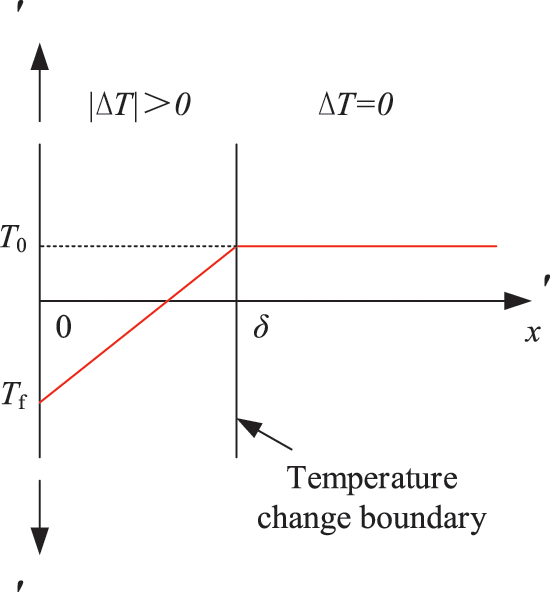
Figure 1: Temperature distribution at a special time t in semi-infinite domain
The equation of initial condition can be represented as Eq. (3).
The equation of boundary conditions can be represented as Eq. (4).
On the basis of
where Gaussian error function
When
The boundary conditions are as shown in Eq. (8).
The Eq. (8) is substituted into Eq. (7), then the formula of temperature distribution is as follows:
Hereafter, the formula of temperature change can be expressed as
According to the following statements, a new frost heaving prediction model is established. (1) The pore water in the soil becomes ice, causing the volume of the soil to expand. The moisture migration causing the frost heaving phenomenon is the main factor. The findings above are discovered by Taber and Beskow through the soil frost heaving test [31,32]. (2) The moisture migration is subject to the temperature gradient [33,34]. In this model, temperature gradient appears in the left zone between
Therefore, the linear frost heaving rate can be calculated as follows:
In which,
Based on the assumptions above, the maximum frost heaving rate can be expressed as Eq. (14).
where
Based on the frost heaving test of saturated soil under hydration conditions,
where we name the coefficient
(2) Two-dimensional model
For two-dimensional model, assume that
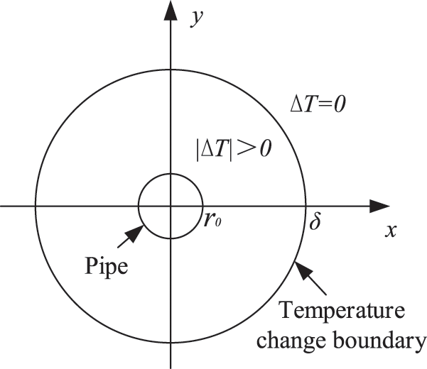
Figure 2: Temperature change distribution based on single pipe in two dimensions
According to the above, the equation of boundary conditions can be represented as
In Eq. (16),
In which,
Therefore, the surface frost heaving rate can be calculated as follows:
where
where the coefficient of cold expansion
(3) Three-dimensional model
The three-dimensional model is composed of multiple two-dimensional models along the longitudinal direction. The numerical simulation of frost heave is based on the model above.
(4) Finite element calculation
Since the elastic modulus varies with temperature, the frost heave strain includes the elastic strain and the temperature strain.
where
The elastic strain increment can be calculated by Hooke's law as follows:
where
Based on the obtained temperature field and the concept of linear expansion coefficient, temperature strain increment can be calculated. The results are as follows:
where
At any period
The node force of the element
The stiffness matrix of the element
Thus, the whole equilibrium equation is as follows:
In which, K is the global stiffness matrix,
The displacement increment
3 Validation of the Frost Heaving Prediction Model: Gongbei Tunnel Case
To verify the validity and feasibility of the proposed frost heaving prediction model, numerical results of the ground uplift due to freeze-sealing pipe roof method is compared with the field measured data. The freeze-sealing pipe roof (FSPR) method combining pipe roofing method and artificial ground freezing method is firstly applied in the Gongbei tunnel with the length of 255 m, which is a critical link of Hongkong-Zhuhai-Macau Bridge. Fig. 3 shows the FSPR structure, which consists of frozen soil and 36 pieces of 1620 mm diameter roofing pipes around the circumference of excavation. The spacing between the pipe edges ranges between 355 to 358 mm. In the normal direction of the tunnel circumference, the odd number roof pipes are shifted by 30 cm to the tunnel direction with respect to the even diameter pipes. The excavation cross-sectional area is approximately 345 m2 with 18.8 m in width and 20.6 m in height, which is the largest single tunnel excavation in China. The tunnel is buried within soft sandy and silty clay about 4.5 m below the ground surface. The purpose of ground freezing is preventing groundwater from entering the tunnel. A freezing process will last for 50 days before excavation. However, the ground surface uplift occurs due to the frost heave. And the amount of frost heave is simulated by the frost heaving prediction model. The correspondingly outcomes are employed to validate the proposed model.
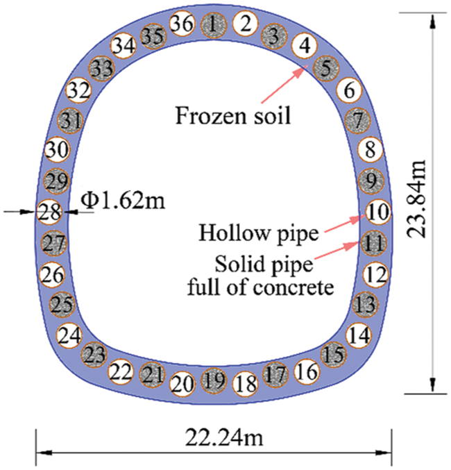
Figure 3: The cross section of FSPR structure
3.2.1 Geometric Model and Material
The ground deformation due to frost heave is simulated using the finite element software ABAQUS. It is assumed that the soil layers are horizontally distributed, isotropic and homogeneous, while roofing pipes and concrete are isotropic homogeneous elastic materials. Refer to the detailed investigation survey data of the Gongbei tunnel, the adjacent soil layers are combined into one layer for calculation. There are five soil layers in the model. The geometry of the model (255 m × 150 m × 60 m in length × width × height) and its cross section are respectively shown in Figs. 4 and 5. The upper surface of the model is ground surface, which is freely constrained. The bottom surface is fully constrained, and the two sides parallel to the tunnel axis are bounded by the normal direction in the x direction. The two sides perpendicular to the tunnel axis are the working well edges constrained by both y and z directions. Tie constraint is adopted between the roofing pipes and surrounding soil. According to the temperature of Zhuhai City in June 2016, the initial temperature of the model is set as 28°C. Since the positive temperature does not cause frost heaving, the value of the initial temperature has little effect on the frost heave calculation. During the freezing phase, the outer surface temperature of roofing pipe is set as −15°C. The soil along the coastal areas expresses elastoplastic properties and can be considered as homogeneous materials. According to the Subsection 2.2 Eq. (15), the coefficient of cold expansion
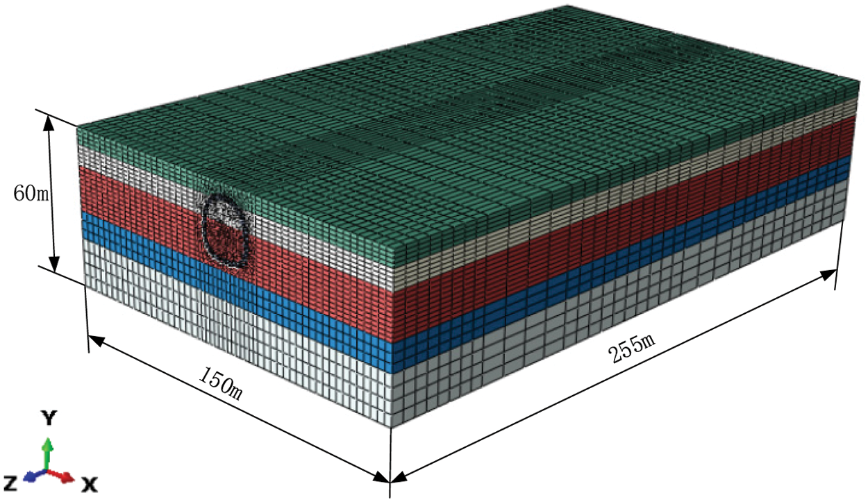
Figure 4: Geometry of the Gongbei tunnel model
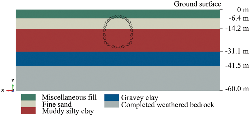
Figure 5: Layout of the roofing pipes in layered soil
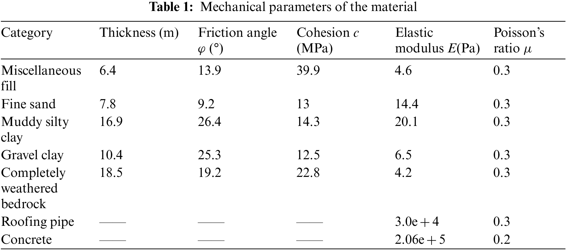
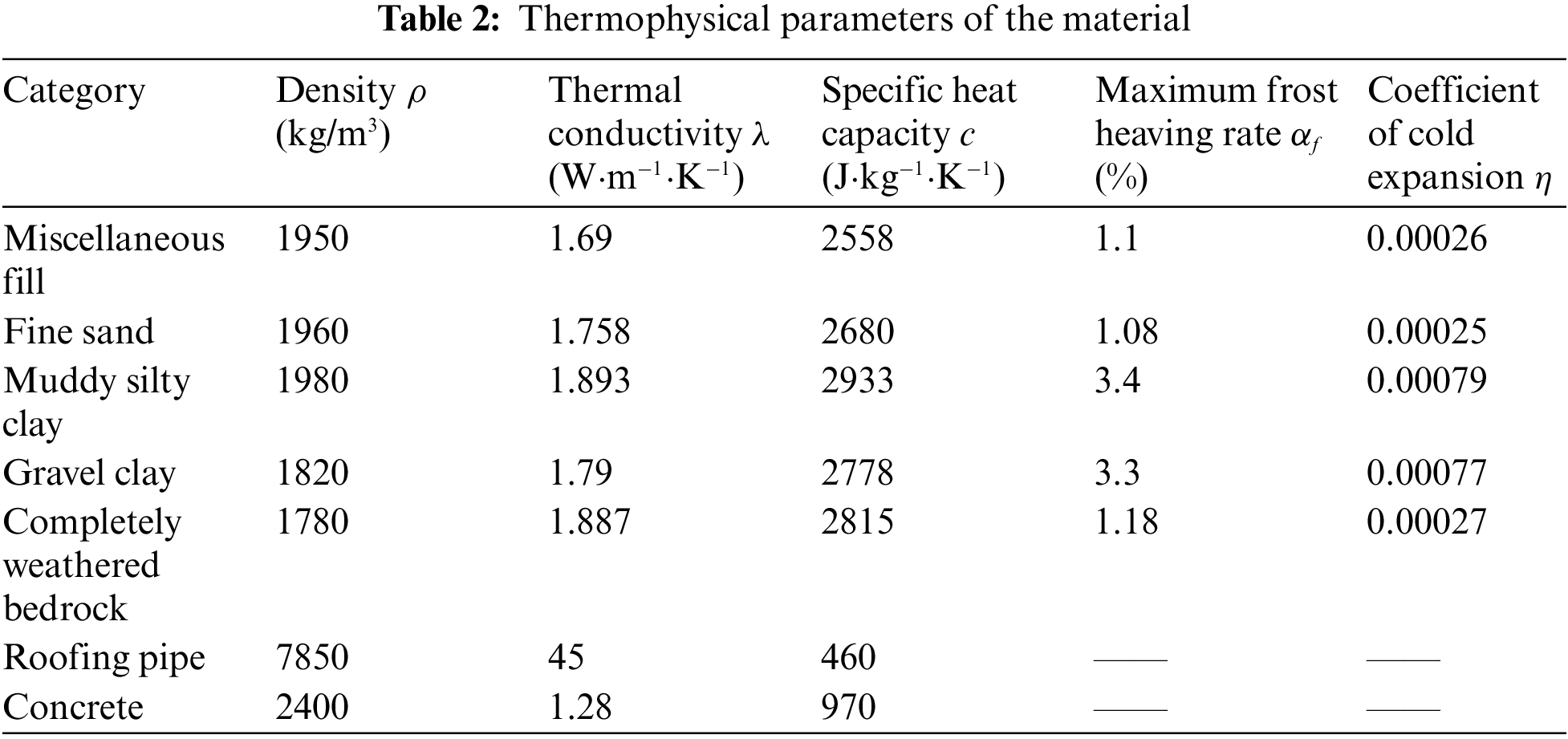
In which, the maximum frost heaving rate is obtained from a model calibration based on soil frost heave test under hydration conditions for each soil layer in laboratory. And the coefficient of cold expansion is calculated according to Eq. (15).
In order to facilitate the analysis of ground surface uplift law, the feature sections are selected, including lateral direction and longitudinal direction. All sections are symmetrically distributed. There are 24 lateral monitoring sections (YK + 390∼YK + 630) along the longitudinal direction, where YK + 400 is the first monitoring section, 10 m from the boundary. Meanwhile, the monitoring data on the corresponding section (YK + 400, YK + 430, YK + 440) is obtained separately, shown in Fig. 6.
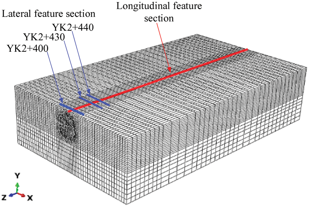
Figure 6: Feature sections
The finite element model consists of soil part, pipe-roofing part, concrete part, and lining part, with a total of approximately 489016 elements, including C3D8T elements and C3D6T elements, shown in Fig. 7. The soil in the coastal area exhibits elastoplastic properties and is considered as a homogeneous material. The Mohr-Coulomb model is used for soil. The pipe roofing, concrete and lining are simulated by an isotropic elastic model. Considering the influence of temperature and frost heave, the coupled temperature-displacement element is chosen and the implementation of frost heave depends on the coefficient of thermal expansion in the ABAQUS software.
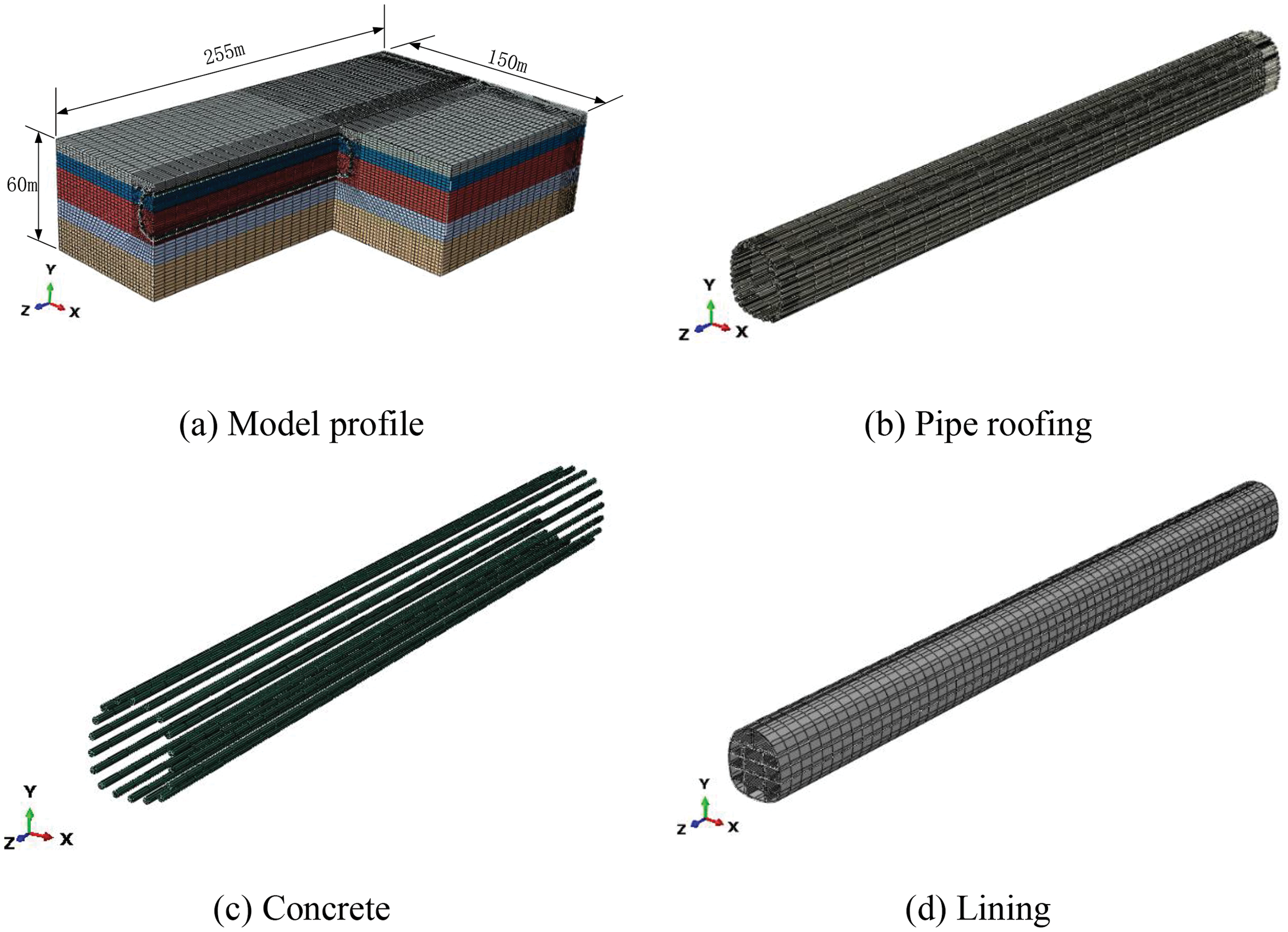
Figure 7: Finite element model
There are 5 steps throughout the whole construction process, containing initial ground stress balance, pipe jacking, backfilling pipe with concrete, soil freezing, tunnel excavation. The ground stress is first released 40% during excavation, and then fully released after support. The main calculation process in Fig. 8 is as follows:

Figure 8: Simulation process
Temperature is one of the factors affecting the frost heave effect, which indirectly affects the soil deformation, therefore the temperature field is the basis for calculating the soil deformation. The initial temperature of the model is 28°C, and the positive temperature does not cause frost heaving. Thus, the value of the initial temperature has little effect on the frost heave calculation. After freezing process of 50 days, the thickness of the frozen soil reaches the required width of 2 m. The temperature distribution is shown in Fig. 9.
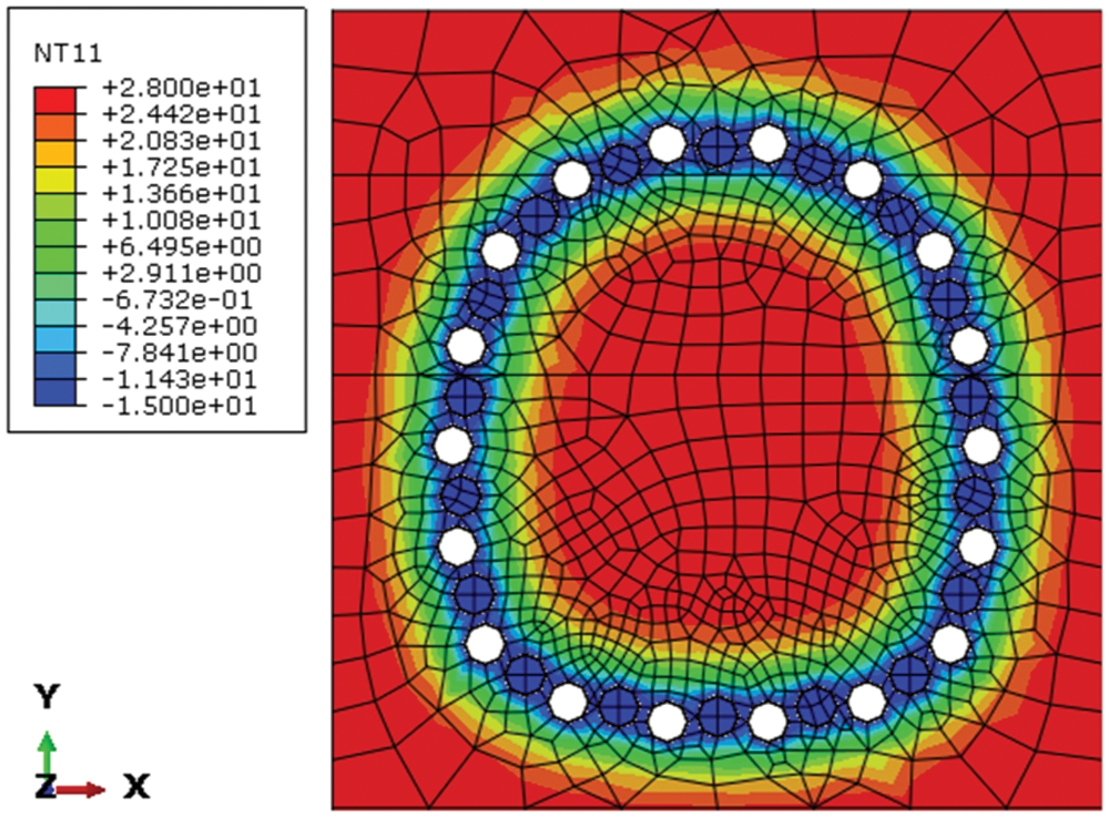
Figure 9: Temperature distribution when freezing for 50 days
The ground equilibrium is achieved by ABAQUS when the surface is horizontal. Then the frost heaving model is applied to predict the vertical uplift of ground surface due to frost heave. Fig. 10 shows the deformation of ground surface uplift after 50 days of freezing. The maximum uplift appears at the center of the model with the value of 285.6 mm, gradually decreasing along the longitudinal and lateral directions. The results along the longitudinal direction are mainly affected by the constraints of the two sides, while the one along the lateral direction is caused by the temperature field distribution.
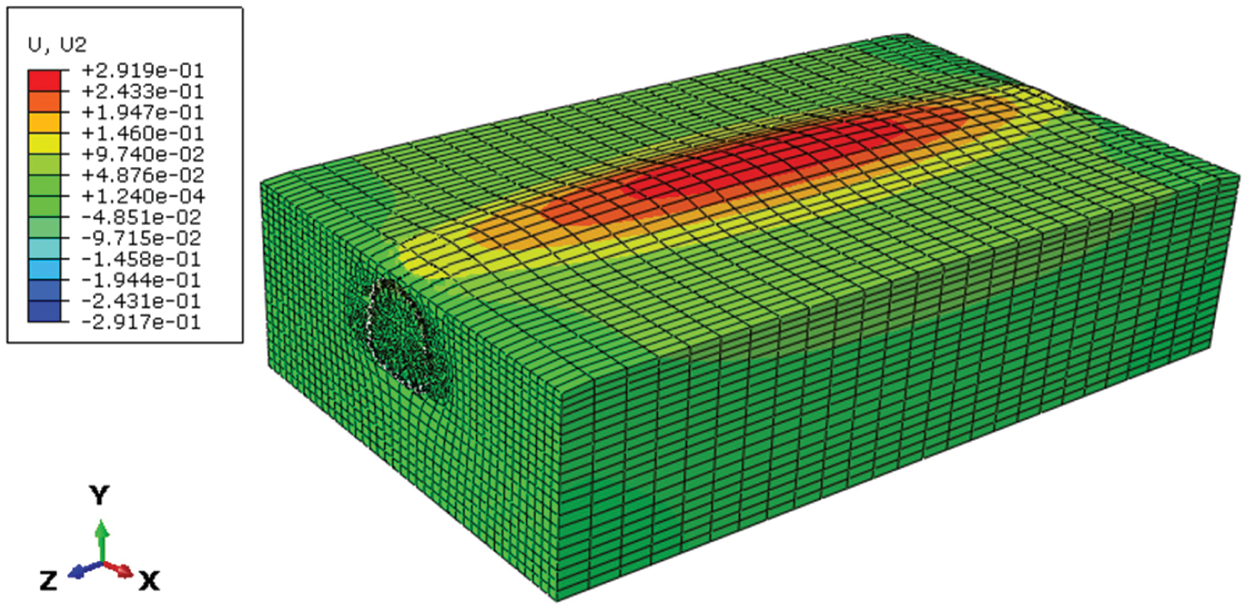
Figure 10: Deformation drawing of ground surface uplift (Zoom in 20 times)
Fig. 11 illustrates the comparison between the results obtained by the model prediction and the field monitoring data at cross section YK2 + 400, YK2 + 430, YK2 + 440 after 50 days of freezing. Both the model simulation results and field monitoring data show that the maximum value of ground surface uplift appears at the symmetry axis of the tunnel section, and the amount of frost heaving on both sides gradually becomes smaller. The curve is shaped like normal distribution. The maximum values of the prediction model curve and the field measured curve at section YK2 + 400 are 75.0 and 72.7 mm, the values of YK2 + 430 are 180.0 and 168.2 mm, and the values at YK2 + 440 are 195.8 and 178.5 mm, respectively. Therefore, the two curves match well in terms of data and shape. Due to the different freezing scheme during different construction period, the curve of the field measurement and model simulation is asymmetric.
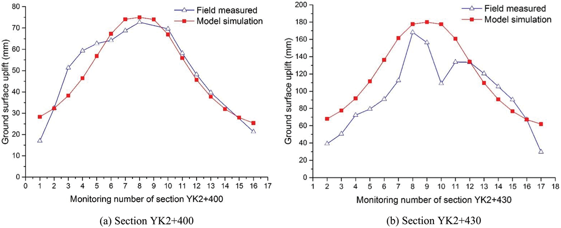
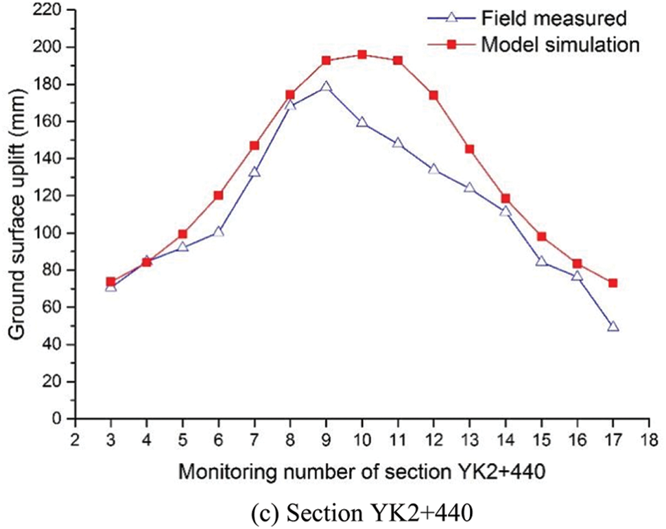
Figure 11: Comparison of model prediction and field monitoring along the cross section
The vertical uplift of ground surface after 50 days of freezing due to frost heave along the longitudinal direction of the tunnel is also analyzed, shown in Fig. 12. The shape of the curve is similar to the parabola with the opening downward. The vertical uplift in the middle span of the tunnel is larger, and the amount of ground uplift near the working wells at both ends is gradually reduced because of the restraining effect from the two sides. Due to the different excavation progress, when the excavation speed is slow, the freezing intensity is relatively high, and the frost heave is relatively large, and vice versa. Therefore, there is a big difference between the field measurement and numerical simulation at 100 and 200 m in the longitudinal direction of the tunnel.
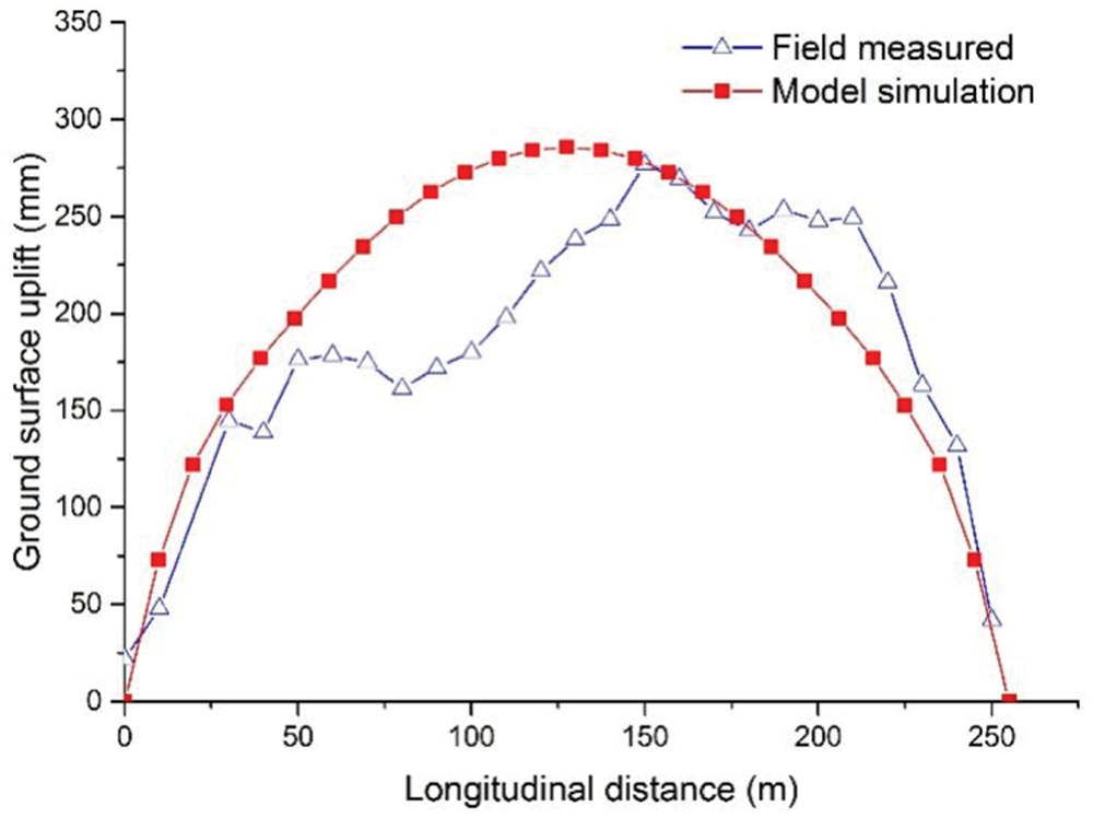
Figure 12: Comparison of model prediction and field monitoring along the longitudinal
A good agreement is discovered between the model prediction and field measured data, except for some misfits that are due to inhomogeneous soil and local grouting that affecting heat transfer and groundwater seepage. In addition, the weight and dynamic load of the surface buildings make the monitoring data slightly smaller than the model result in some local location. The favorable agreement indicates that the proposed frost heaving prediction model can well predict the ground surface uplift due to frost heave.
The ground deformation due to FSPR method involves a complicated hydrothermal coupling process, which is difficult to accurately simulate. According to that, a frost heaving prediction approach is proposed to simulate ground deformation of the Gongbei tunnel. The proposed model deals with the frost heave calculation by combining the coefficient of cold expansion based on the calculation equation and the frost heaving test under hydration conditions. From the result analysis of prediction model and field monitoring, some conclusions are drawn:
(1) The coefficient of cold expansion in model and the frost heaving rate from the test under the hydration condition can achieve a good correspondence that makes the calculation result closer to the actual engineering.
(2) The numerical simulation and monitoring data of the Gongbei tunnel are employed to validate the proposed model, and a good agreement between the frost heaving prediction model and the field measured data verifies the rationality and applicability of the proposed model to predict the ground deformation.
(3) The maximum uplift of the Gongbei tunnel appears at the center of the model, gradually decreasing along the lateral and longitudinal directions. The result in the lateral direction represents a normal distribution due to the influence of the constraint of two sides, while the one along the lateral direction shapes like a parabola with the opening downward due to the temperature field distribution.
It should be noted that the application of the proposed frost heaving prediction model to the Gongbei tunnel will be a reference for similar cases.
Acknowledgement: The author wishes to thank the high-performance computing cluster of Computer Science Department at Princeton University and the editor Dr. Lynn Wang for the careful format review.
Funding Statement: This work is supported by the financial support from National Natural Science Foundation of China (No. 51478340), Natural Science Foundation of Jiangsu Province (No. BK20200707), The Natural Science Foundation of the Jiangsu Higher Education Institutions of China (No. 20KJB560029), China Postdoctoral Science Foundation (No. 2020M671670), Key Laboratory of Soft Soils and Geoenvironmental Engineering (Zhejiang University), Ministry of Education (No. 2020P04), the support above is gratefully acknowledged.
Conflicts of Interest: The authors declare that they have no conflicts of interest to report regarding the present study.
1. Hu, X., Deng, S., Ren, H. (2017). In situ test study on freezing scheme of freeze-sealing pipe roof applied to the gongbei tunnel in the Hong Kong-Zhuhai-Macau Bridge. Applied Sciences, 7(1), 27. DOI 10.3390/app7010027. [Google Scholar] [CrossRef]
2. Hu, X., Deng, S., Wang, Y. (2018). Analytical solution to steady-state temperature field with typical freezing tube layout employed in freeze-sealing pipe roof method. Tunnelling and Underground Space Technology, 79, 336–345. DOI 10.1016/j.tust.2018.06.014. [Google Scholar] [CrossRef]
3. Hong, Z., Hu, X., Fang, T. (2020). Analytical solution to steady-state temperature field of freeze-sealing pipe roof applied to gongbei tunnel considering operation of limiting tubes. Tunnelling and Underground Space Technology, 105, 571. DOI 10.1016/j.tust.2020.103571. [Google Scholar] [CrossRef]
4. Bronfenbrener, L., Bronfenbrener, R. (2010). Modeling frost heave in freezing soils. Cold Regions Science and Technology, 61, 43–64. DOI 10.1016/j.coldregions.2009.12.007. [Google Scholar] [CrossRef]
5. Xia, C., Lv, Z., Wang, Y. (2020). Advance and review on frost heaving force calculation methods in cold region tunnels. China Journal of Highway and Transport, 33, 35–43. DOI 10.3969/j.issn.1001-7372.2020.05.003. [Google Scholar] [CrossRef]
6. Miller, R. (1978). Frost heaving in non-colloidal soils. Proceedings of 3rd International Conference on Permafrost, pp. 708–713. Ottawa, Canada. [Google Scholar]
7. O'Neill, K., Miller, R. (1980). Numerical solutions for a rigid-ice model of secondary frost heave. 2nd International Symposium on Ground Freezing, pp. 656–669. Trondheim, Norway. [Google Scholar]
8. Rajaei, P., Baladi, G. (2015). Frost heave: A semi-empirical model based on field data. 16th International Conference on Cold Regions Engineering, pp. 382–393. Salt Lake City, Utah. [Google Scholar]
9. Lai, Y., Pei, W., Zhang, M., Zhou, J. (2014). Study on theory model of hydro-thermal-mechanical interaction process in saturated freezing silty soil. International Journal of Heat and Mass Transfer, 78, 805–819. DOI 10.1016/j.ijheatmasstransfer.2014.07.035. [Google Scholar] [CrossRef]
10. Konrad, J., Morgenstern, N. (1981). The segregation potential of a freezing soil. Canadian Geotechnical Journal, 18, 482–491. DOI 10.1139/t81-059. [Google Scholar] [CrossRef]
11. Konrad, J., Morgenstern, N. (1982). Effects of applied pressure on freezing soils. Canadian Geotechnical Journal, 19, 494–505. DOI 10.1139/t82-053. [Google Scholar] [CrossRef]
12. Konrad, J. (1993). Frost heave in soil: Concepts and engineering. Canadian Geotechnical Journal, 31, 223–245. DOI 10.1139/t94-028. [Google Scholar] [CrossRef]
13. Konrad, J. (2005). Estimation of segregation potential of finegrained soils using the frost heave response of two reference soils. Canadian Geotechnical Journal, 42, 38–50. DOI 10.1139/t04-080. [Google Scholar] [CrossRef]
14. O'Neill, K., Miller, R. (1985). Exploration of a rigid ice model of frost heave. Water Resources Research, 21, 281–296. DOI 10.1029/WR021i003p00281. [Google Scholar] [CrossRef]
15. Harlan, R. (1973). Analysis of coupled heat-fluid transport in partially frozen soil. Water Resources Research, 9, 1314–1323. DOI 10.1029/WR009i005p01314. [Google Scholar] [CrossRef]
16. Fromend, M., Mikkola, M. (1991). Thermomechanical modeling of freezing soil. Proceeding of 6rd Inernational Symposium on Ground Freezing, pp. 17–24. Beijing, China. [Google Scholar]
17. Zheng, H., Kanie, S. (2015). Combined thermal-hydraulic-mechanical frost heave model based on Takashi's equation. Journal of Cold Regions Engineering, 29(4), 1–19. DOI 10.1061/(ASCE)CR.1943-5495.0000089. [Google Scholar] [CrossRef]
18. Wu, Y., Zhai, E., Zhang, X., Wang, G., Lu, Y. (2021). A study on frost heave and thaw settlement of soil subjected to cyclic freeze-thaw conditions based on hydro-thermal-mechanical coupling analysis. Cold Regions Science and Technology, 188, 1–10. DOI 10.1016/j.coldregions.2021.103296. [Google Scholar] [CrossRef]
19. Li, Z., Yao, X., Zhang, R., Shao, H., Wang, Z. (2020). Frost heave mechanical model of concrete lining trapezoidal canal considering nonuniform frost heave of foundation soil based on elastic foundation beam theory. Nongye Gongcheng Xuebao/Transactions of the Chinese Society of Agricultural Engineering, 36(21), 114–121. DOI 10.11975/j.issn.1002-6819.2019.15.015. [Google Scholar] [CrossRef]
20. Lv, Z., Xia, C., Li, Q., Si, Z. (2019). Empirical frost heave model for saturated rock under uniform and unidirectional freezing conditions. Rock Mechanics and Rock Engineering, 52(3), 955–963. DOI 10.1007/s00603-018-1666-z. [Google Scholar] [CrossRef]
21. Zheng, L., Gao, Y., Zhou, Y., Tian, S. (2020). Research on surface frost heave and thaw settlement law and optimization of frozen wall thickness in shallow tunnel using freezing method. Yantu Lixue/Rock and Soil Mechanics, 41(6), 2110–2121. DOI 10.16285/j.rsm.2019.1102. [Google Scholar] [CrossRef]
22. Tang, L., Yang, L., Wang, X., Yang, G., Ren, X. et al. (2021). Numerical analysis of frost heave and thawing settlement of the pilesoil system in degraded permafrost region. Environmental Earth Sciences, 80(20), 1–19. DOI 10.1007/s12665-021-09999-4. [Google Scholar] [CrossRef]
23. Feng, Q., Jiang, B. S., Zhang, Q., Wang, L. P. (2014). Analytical elasto-plastic solution for stress and deformation of surrounding rock in cold region tunnels. Cold Regions Science and Technology, 108, 59–68. DOI 10.1016/j.coldregions.2014.08.001. [Google Scholar] [CrossRef]
24. Lai, Y., Wu, Z., Zhu, Y., Zhu, L. (2000). Elastic visco-plastic analysis for earthquake response of tunnels in cold regions. Cold Regions Science and Technology, 31, 175–188. DOI 10.1016/S0165-232X(00)00011-2. [Google Scholar] [CrossRef]
25. Yang, P., Ke, J., Wang, J., Chow, Y., Zhu, F. (2006). Numerical simulation of frost heave with coupled water freezing, temperature and stress fields in tunnel excavation. Computers and Geotechnics, 33, 330–340. DOI 10.1016/j.compgeo.2006.07.006. [Google Scholar] [CrossRef]
26. Zheng, L., Gao, Y., Zhou, Y., Liu, T., Tian, S. (2021). A practical method for predicting ground surface deformation induced by the artificial ground freezing method. Computers and Geotechnics, 130, 1–16. DOI 10.1016/j.compgeo.2020.103925. [Google Scholar] [CrossRef]
27. Zhou, J., Zhao, W., Tang, Y. (2021). Practical prediction method on frost heave of soft clay in artificial ground freezing with field experiment. Tunnelling and Underground Space Technology, 107, 1–17. DOI 10.1016/j.tust.2020.103647. [Google Scholar] [CrossRef]
28. Wen, Z., Sheng, Y., Jin, H. (2010). Thermal elasto-plastic computation model for a buried oil pipeline in frozen ground. Cold Regions Science and Technology, 64, 248–255. DOI 10.1016/j.coldregions.2010.01.009. [Google Scholar] [CrossRef]
29. Na, S., Kebria, M., Roy, K. (2020). A coupled thermo-hydro-mechanical model for capturing frost heave under chilled gas pipelines. 13th International Pipeline Conference, IPC, Virtual, American Society of Mechanical Engineers (ASME), pp. 1–6. Calgary, AB, Canada. [Google Scholar]
30. Hawlader, B., Morgan, V., Clark, J. (2006). Modelling of pipeline under differential frost heave considering post-peak reduction of uplift resistance in frozen soil. Canadian Geotechnical Journal, 43, 282–293. DOI 10.1139/t06-003. [Google Scholar] [CrossRef]
31. Taber, S. (1930). The mechanics of frost heaving. Journal of Geology, 38, 303–317. DOI 10.1086/623720. [Google Scholar] [CrossRef]
32. Beskow, G. (1935). Soil freezing and frost heaving with special application to roads and railroads. The Swedish Geological Society Year Book No. 3. Chicago: Northwestern University. [Google Scholar]
33. Philip, J., DeVries, D. (1957). Moisture movement in porous material under temperature gradients. Transaction of American Geophysical Union, 38, 222–232. DOI 10.1029/TR038i002p00222. [Google Scholar] [CrossRef]
34. Milly, C. (1982). Moisture and heat transport in hysteretic, in homogeneous porous medias: A matrix head-based formulation and a numerical model. Water Resources Research, 18, 489–498. DOI 10.1029/WR018i003p00489. [Google Scholar] [CrossRef]
 | This work is licensed under a Creative Commons Attribution 4.0 International License, which permits unrestricted use, distribution, and reproduction in any medium, provided the original work is properly cited. |