| Computer Modeling in Engineering & Sciences |
DOI: 10.32604/cmes.2022.018840
ARTICLE
Conceptual Design Process for LEO Satellite Constellations Based on System Engineering Disciplines
Faculty of New Sciences and Technologies, University of Tehran, Tehran, Iran
*Corresponding Author: Mahdi Fakoor. Email: mfakoor@ut.ac.ir
Received: 20 August 2021; Accepted: 24 November 2021
Abstract: Satellite design process is an interdisciplinary subject in which the need for collaboration among various science and engineering disciplines is evident. Meanwhile, finding an optimal process for conceptual design of a satellite, which can optimize time and cost, is still an important issue. In this paper, based on system engineering approach, an optimal design process is proposed for LEO satellite constellations. In the proposed method, design process, design sequences, and data flow are established. In this regard, the conceptual design process is divided into two levels of mission (or constellation) and system (or satellite) as well as 15 main activities based on the mission profile, previous experiences of the authors, and existing literature. Then, the relationships between these activities have been determined by considering the importance of relationships according to their priority. Finally, these relations are optimized based on design structure matrix (DSM). By utilizing this approach, system design process of a telecommunication satellite constellation in LEO is formulated in conceptual design phase. Performance and capability of the proposed approach in optimal design process of the satellite constellation are investigated by comparing the outcome with existing results in the literature.
Keywords: Satellite constellation; system engineering; design structure matrix; conceptual design
Employing a satellite to satisfy complex missions such as the coverage of an extensive region has limitations. Satellite constellation can be replaced as an effective solution to perform complex missions. Although the use of satellite constellation can reduce some complexities and costs in space missions, adopting a suitable method for designing constellation is challenging [1].
Space technology is categorized in multidisciplinary industries which need the cooperation of different disciplines of science, from various engineering fields to economics and project management. All these suggest that system engineering is a crucial issue in design of space systems. These reasons highlight the importance of using systematic methods to improve the design procedures of space systems and to understand the relationship between design parameters. Finding an optimal solution for the conceptual design of a satellite that can minimize time and cost is still a challenging issue. Indeed, establishing a systematic procedure to remove critical design loops and reduce the time of design process are important in design of space systems [2].
Planning for agile system design has been carried out in some space projects [3,4]. In recent years, several efficient tools have been developed to improve system design of the satellites. MUSSat is an efficient tool for satellite system design, which was proposed based on various models derived from satellite data banks. In MUSSat, according to taken data from existing satellites, a model and the relationship between design parameters are presented [5]. System engineering module (SEM) is another tool provided to develop satellite system design. In SEM, a data bank is used to estimate the relationship between the design parameters in a graphical environment. SEM is more complete than MUSSat, and considers the design at a sub-system level [6]. A system level tool for conceptual design was also proposed based on an estimated model of data banks. This tool has been designed for nano-and microsatellites [7]. Mirshams et al. [8] presented a system engineering tool for platform conceptual designof GEO satellites. Fakoor et al. [9] proposed SCALE as an efficient optimization tool for layout design of satellites considering different constraints. Chang et al. [10] proposed a system engineering design tool (SEDT) for the conceptual design phase of the satellites. SEDT provides system and subsystem budgeting considering inputs such as mission type, orbit, and specifications of subsystem. Note that most of the proposed models for satellite conceptual design are based on statistical data. The difficulty in gaining accessing to statistical information is a major problem of these methods.
Design Structure Matrix (DSM), presented by Steward [11], is a system engineering tool that provides a visual, simple, and compact representation of complex systems [12,13]. One of the most important functions of DSM is improving the design processes. The design process of a space project, such as a satellite, involves a collection of various activities that will work together and in close interaction with each other. Failure to correctly identify the interactions and the inappropriate sequence of activities can lead to longer time and higher cost of the project, or even the failure of the entire project [14]. The DSM can help in better understanding the system by displaying appropriate interactions between various activities or working teams. Also, DSM has been utilized for optimizing the design process of complex projects such as satellites. DSM is widely used in engineering projects for the design of complex systems with several subsystems [15–20]. In this regard, Qiao et al. [21] utilized DSM to design a formation flying for synthetic-aperture radar (SAR) satellites. Several studies have also been conducted on the combination of DSM with management concepts [19]. Lee et al. [22] combined DSM and the work breakdown structure (WBS) to propose a process for decomposition and integration of complex projects.
Based on the presented literature, so far, there has been no specific approach for conceptual design of satellite constellation [23] as a specific and multi-level process by providing details of the relationship of activities and work teams.
In this paper, in order to obtain the optimal system design process for the constellation satellite system, firstly, based on the mission profile of the constellation, the design process is broken down into two main levels of activities and the relationships between different activities are examined. All relationships among different activities in the conceptual design process of LEO satellite constellations are identified carefully. The system design process is characterized by DSM and optimized to achieve the best design sequence. In the employed method, design loops are minimized significantly.
A telecommunication satellite constellation is considered as a case study. The mission transfers data to ground stations. This constellation consists of a number of similar satellites that are connected together and can send data directly or through inter-satellite links (ISL) to ground stations. Accordingly, in order to complete the mission, a number of similar satellites are required which can also use the necessary facilities to support the mission in addition to the equipment for transmitting data and inter-satellite links. The performance and capability of the proposed method in the optimal design process of the satellite constellation are validated based on the available literature.
2 Overview of Design Structure Matrix (DSM)
One of the common problems in large and complex projects is the existence of design loops that introduce complicated problems in determining the design activity sequence, and increase the time of design process. In large and complex engineering projects such as space projects, due to ambiguity, complexity, and numerous variables, the existence of design loops is inevitable. Nevertheless, the fact is that many of the common loops in these projects are avoidable, but due to the large number of parameters and activities, the actual analysis of the loops cannot be done by humans using common tools. Via design structure matrix (DSM), unnecessary design loops could be eliminated and unavoidable ones can be minimized. The presence of each element above the main diagonal of DSM matrix represents a loop. The simplest way for optimizing the design loops is to make DSM a triangular bottom matrix. Sometimes, all design loops cannot be completely eliminated, due to the interdependence of different elements to each other. In these cases, the remaining design loops should be shortened as much as possible to reduce the time and cost of the project. To do this, the elements closer to the main diagonal should be drawn [13]. After employing these algorithms, the following sub-processes that can be done independently of each other could be identified. Even if a loop remains, the loop is usually defined as an independent activity. When the number of elements grows, employing the mentioned algorithm is extremely difficult for a human. In these cases, computer and numerical solutions could be utilized. The important issue about discovering the dependence of activities on each other and completing the DSM is that, in complex systems such as the satellite constellation, almost all main components have interfaces with each other, but not all interfaces have an equal priority in the design process. Thus, according to the priority of the interfaces, the design process will be defined.
As a conclusion, it could be stated that for employing DSM and extracting the optimal process, first, the process should be broken into some activities with similar weights, then the interfaces between the activities will be specified. As mentioned, in some cases, it is necessary to determine the level of priority of the interface (Weighted-DSM), or that only high priority interfaces are introduced into the matrix. Then, the matrix is formed and completed, and finally the matrix is optimized based on the mentioned algorithms. Note that in this research, DSM was employed to develop the design process of LEO telecommunication satellites. All activities are divided into two priority levels and only high-priority interfaces are introduced in the matrix.
3 Process Breakdown into Major Activities at Mission and System Levels
The present research attempts to achieve optimal conceptual design of satellite constellation. In this regard, the goal is to define an optimal design process where the input of each step would be produced at the end of the previous step. For this purpose, the mission profile of the satellite constellation should be investigated based on the system operation. Different functions should be performed during operation modes and the relationship between different activities should be defined based on the mission profile.
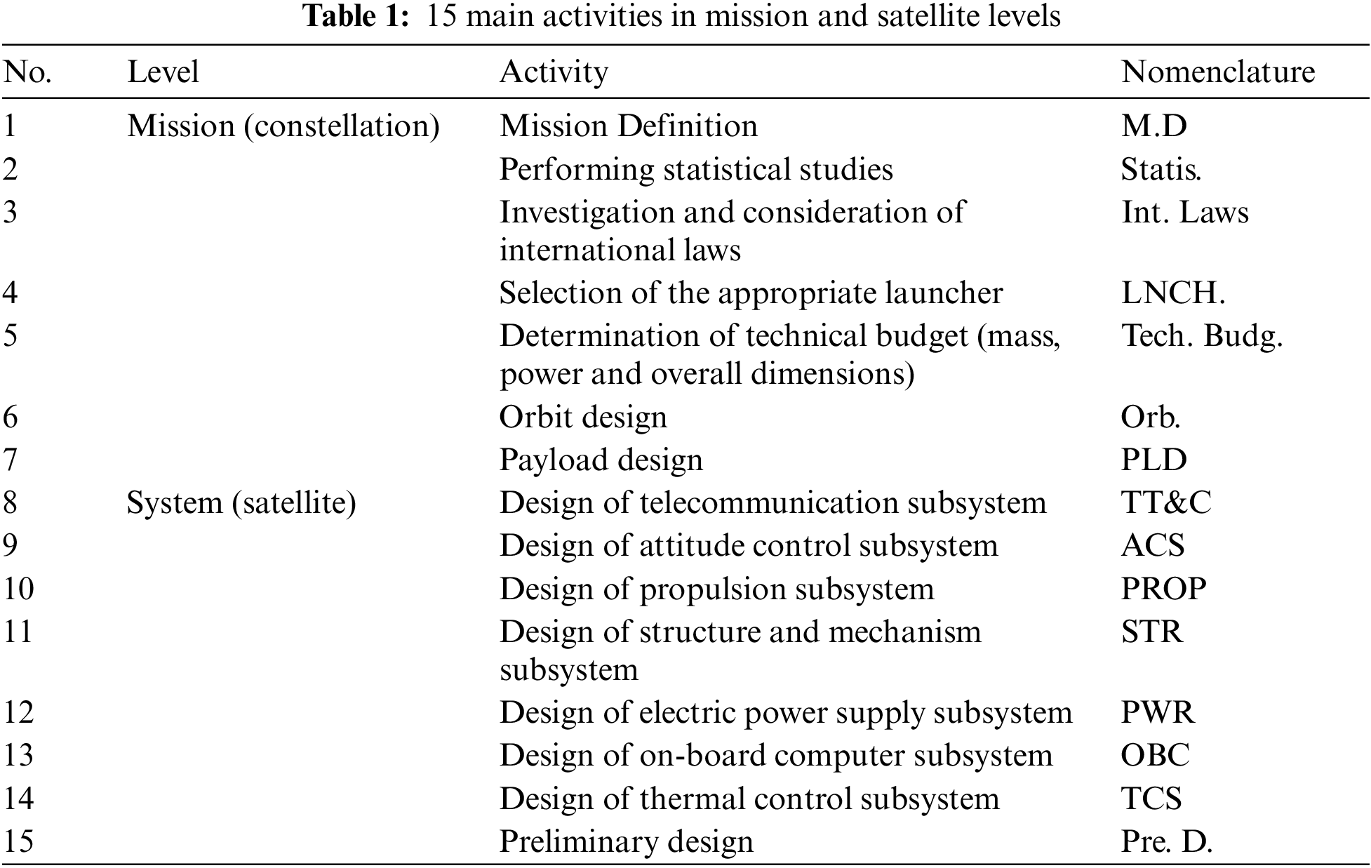
Based on the opinions of satellite chief designer, requirements of subsystems, and the available experiences in our design team, system design process is broken into two mission levels (constellation) consisting of seven activities and system level (satellite) including eight activities (15 total activities with the same weight). The output of higher design levels provides input for lower levels. The list of 15 main activities and related explanations are reported in Table 1.
Note that the input of this step is the customer's need, while the output provides suitable sequencing for design activities. Another input for the interface matrix with a high priority level between the activities will be presented in the next section.
In the following, the interface between different activities is established. Nevertheless, with more careful consideration, it becomes clear that the two factors cause errors in these cases: “indirect relationship” and “mutual relationship”. In the case of indirect relationship, two subsystems are interrelated to each other with an intermediate subsystem, while mutual relationship refers to the common case in which subsystems have a two-way relationship. Note that in mutual relationship, requirements of the stronger route should be considered. The basis of this priority is customer requirements, environmental and technological constraints, as well as generally high-order constraints and requirements. These priorities will be determined based on the experience of previous designers on similar satellites.
The next step attempts to use the design structure matrix for analyzing the interfaces and for defining as well as extracting the process. The lack of proper recognition of indirect and direct interdependencies or neglecting high-order requirements and constraints could complicate DSM and its analysis. Such a process, especially at the conceptual design level, will affect the time and cost of the project. It was not possible to pass through this step only by relying upon the experience of experts and with a systematic approach. In the following, some examples of these priorities are presented:
• The assumption is that the orbital pattern has been designed based on the mission profile; accordingly the launcher, launch window, propulsion, and similar items are determined.
• Launcher determines the inclination.
• The launch time must satisfy the constrain of launch window.
• The inter-satellite communication is base and the communication platform of the satellites is determined based on ISL.
It is emphasized that design of each subsystem is implicitly dependent on the design of all other subsystems. This leads us to a complicated design process. Thus, with a simplified assumption, two categories of subsystem interfaces are defined. The first category is high-priority interfaces and the second is normal priority. In this section, each activity is described and high-priority interfaces are recognized.
The next section presents more descriptions about different working teams, their interactions, interfaces, and the design plus information flow. Also, all priorities in interfaces will be recognized and described. The output of this step is sequencing conceptual design process, specific outputs of each step, and pattern of information flow between working teams.
In mission definition phase, the customer's need converts to technical and engineering requirements. MD takes input from the client’s requirement, which is the highest level, and does not take any input from the mission level. Based on the output of this phase, the scope of statistical studies is determined and it also determines which category of international rules regarding the system is necessary to be investigated. The output of this step is the main features of the mission of the satellite constellation, including the coverage area and the mission life [24,25].
3.1.2 Performing Statistical Studies
According to the defined mission, statistical studies are carried out on similar systems to estimate the total mass, total volume, total power, the orbital parameters, and the number of satellites required for the system and similar items. The results of this step could be used in “determination of technical budget” and “orbit design” activities.
3.1.3 Investigation and Consideration of International Laws
Considerations of international laws and regulations relating to telecommunication frequencies applicable to satellite communications (space-to-space) are the most important issue in design process of satellite constellation. Based on the output of the “mission definition”, this activity can be initiated and the output of this activity will be a good input for “determination of technical budget” activity.
3.1.4 Selection of the Appropriate Launcher
Before designing satellite constellation, it should be ensured that there is a suitable launcher. The proper launcher should be able to carry the satellites with specific mass and volume at the desired height. On the other hand, there are limitations in selection of the launcher. The number of launchers that can be selected in a space project is limited. Electromagnetic effects and interactions of the launcher on the satellite as well as the effect of launcher vibrations in different phases and modes are related to the normal priority level. Although they are ignored in completing the DSM, but at the time of designing the process, these are of interest issue.
3.1.5 Determination of Technical Budget (Mass, Power and Overall Dimensions)
The satellite’s technical characteristics such as mass, power and volume are estimated based on statistical data. However, due to the limited choice of launcher, these features may not be compatible with the ability of selected launcher. In these cases, unfortunately, technical specifications could be changed to match the launcher limitations. Therefore, we must return to the mission profile and change the mission and high order requirements. In these cases, the technical characteristics can affect the mission definition.
Orbital design requires large number inputs from MD. In the cases where there is a limitation in choosing the launcher, the appropriate launcher should be selected firstly, and then the orbit design should be performed. Therefore, based on the launcher’s ability and predicted weight for the satellite, as well as based on statistical studies previously performed on the basis of the mission, the orbital features will be determined so that the constellation can provide the mission properly. In orbital analysis of the constellation, number of orbital planes, inclination, orbit height, and the number of satellites in each plane will be determined. One of the outputs of orbit design activity is the number of satellites necessary to carry out the mission of the constellation and the distance between the satellites. The distance between satellites will be an important input for payload design activities and ISL. Other outcomes of this step are the height of the orbit, which allows us to determine the atmospheric drag for the design of the attitude control subsystem. Also, the outputs of this activity, such as the height of the orbit and the atmospheric drag at this height, will be important inputs for the design of the propulsion subsystem. Utilizing these inputs, technical characteristics for orbital maneuvers are determined. Eclipse time and similar items that are output of orbital design activity will be important inputs for design of the power and the thermal control subsystems. The orbit design will determine the accuracy of the pointing for the attitude control subsystem and it will also be effective in designing the propulsion subsystem [26–28].
3.1.7 Payload and ISL Design Activity
Payload is one of the most important subsystems in the design process of each satellite, because the main mission is performed by means of the payload, and all other subsystems are providing a platform for the payload. ISL will send satellite data to the other satellites which have access to ground stations when the satellite is not over ground stations, to meet the requirement of timely sending data. The design of the inter-satellite link subsystem is a multidirectional design. Particularly, the design of this subsystem generally influences other subsystems and it also specifies their specifications. The interface between activities and data flow at the mission level has been illustrated in Fig. 1. The links of activities and data flow between the level of the mission and the system level have been presented in this figure.
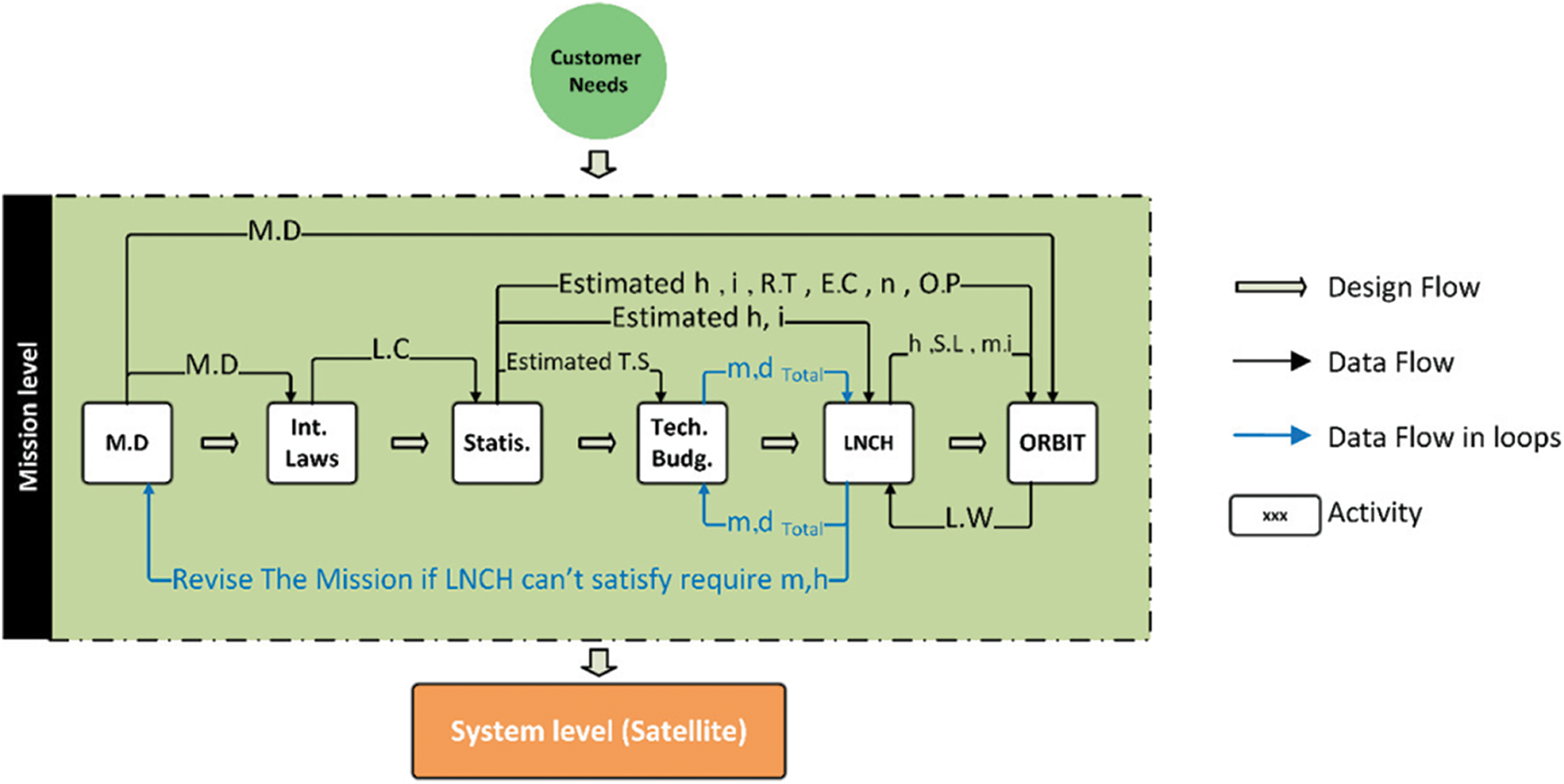
Figure 1: The interface between activities and data flow at the mission level
In the case of the payload subsystem, it is necessary to determine the link budget by satellite mission. Flowchart of activities in payload subsystem is presented in Fig. 2.
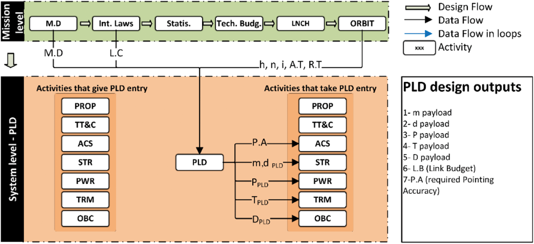
Figure 2: Flowchart of activities in payload subsystem
3.2 System Level of Constellation (Satellite)
The considered constellation includes number of satellites that are capable to send data to the ground stations and also equipped with inter-satellite links. The satellite system consists of two main parts of the payload and platform. The payload (PLD) consists of inter-satellite link (ISL), which supported by seven other subsystems including electric power supply (PWR), telecommunication (TTC), attitude control (ACS), structure and mechanism (STR), propulsion (PROP), thermal control (TCS) and on-board computer (OBC).
3.2.1 Activities for Telecommunication Subsystem Design
The task of the telecommunication subsystem (TT&C) is establishing satellite links with the ground station. This subsystem should satisfy two main requirements, i.e., transfer mission data to the ground station and receive telemetric and the other appropriate commands from ground stations. Therefore, this subsystem should be ready in all time. In designing TT&C, it is necessary to determine the link budget based on the defined mission with the help of the design team of the inter-satellite links. Revisit time and access time are also required to determine and design the type of telecommunication antenna and other related items that, this data will be provided by the orbit design team. The designer of this subsystem should be reported the amount of generated heat, the amount of power required, the amount of information processing and the mass of the subsystem to the design team [29–31]. Flowchart of activities in TT&C subsystem has been shown in Fig. 3.
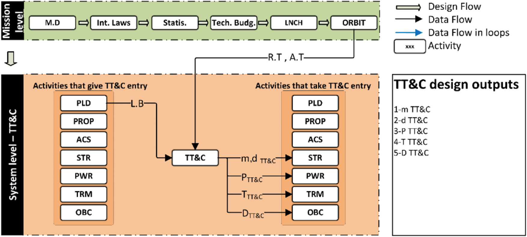
Figure 3: Flowchart of activities in the telecommunications subsystem (TT&C)
3.2.2 Activities for Attitude Control Subsystem (ACS) Design
ACS has two main tasks of attitude determination and control of the satellite. In this regard, firstly, position of each satellite should be determined utilizing sensors, such as sun and star sensors. Then, position of the satellite should be controlled and placed into the desired attitude in orbit using related actuators such as reaction wheels and magneto-torquer. Most of the ASC design requirements (such as pointing accuracy) and inputs (such as moments of inertia and center of mass) are taken from payload and structure subsystems. This subsystem, also declares mass, dimensions, produced heat, the amount of data processing, and its required power to the corresponding subsystems. The effects of disturbances and atmospheric drag on satellite attitude control should be analyzed having orbital data. There will be a very important loop between attitude control subsystem and structural team for the link between the total mass, the location of the center of mass and the moment of inertia, and the control of the status of the satellite [32,33]. Flowchart of design activities for attitude control subsystem is presented in Fig. 4.
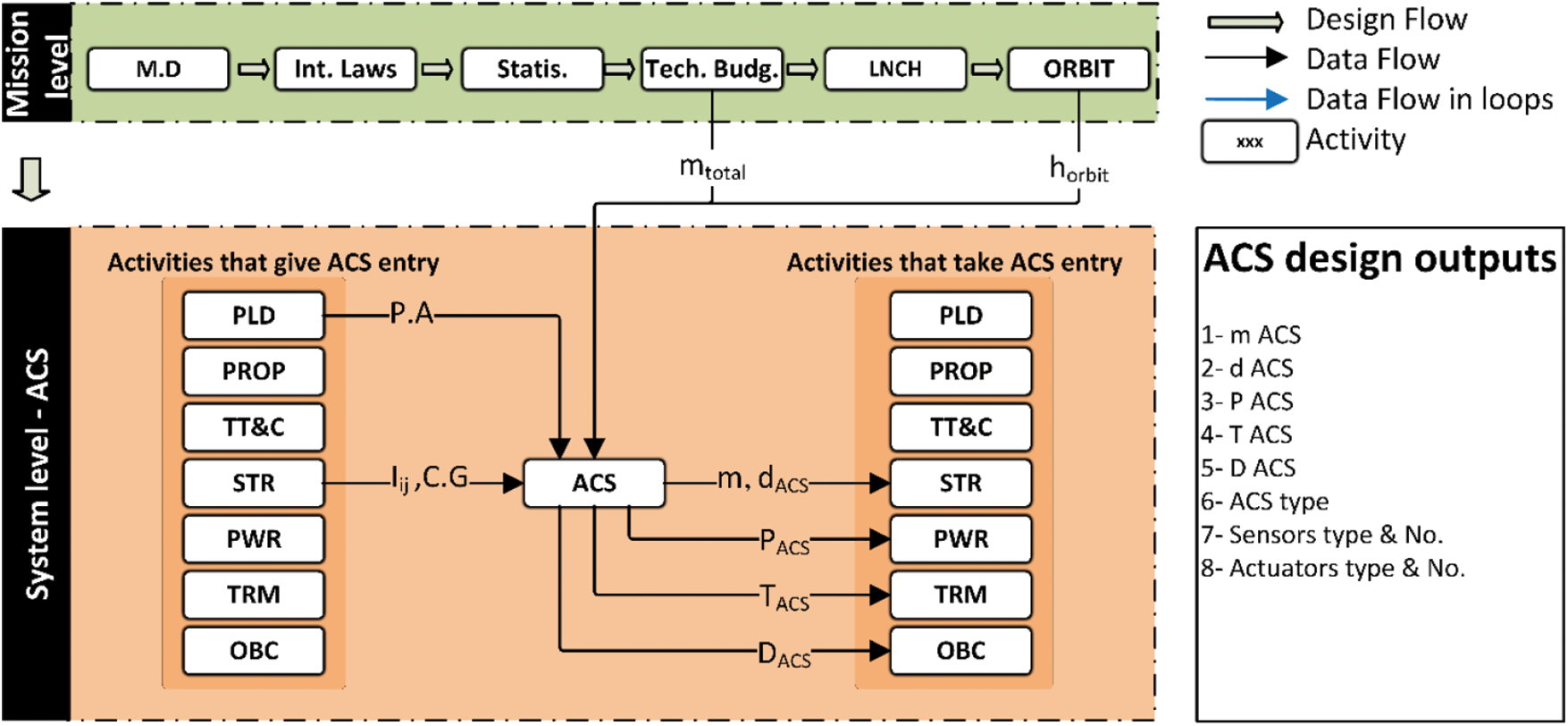
Figure 4: Flowchart of design activities for attitude control subsystem (ACS)
3.2.3 Activities for Propulsion Subsystem Design
After separation of the satellite from the launcher, the propulsion subsystem has two main tasks. The first one is orbital transfer in which the satellite should be placed in an appropriate position in the constellation [34] and in a suitable orbit. The other one is orbital modification. Orbital disturbances, atmospheric drag and gravity are the most important parameters which divert satellites from their original orbit. In this situation, depending on the mission profile, the orbital modification process will be carried out by the propulsion subsystem. Mass, dimension, generated heat and orbital life time are the most important considerations included in the design of this subsystem. In design of the propulsion subsystem, there is almost no initial dependence on system level activities and the main inputs of this activity are received from the mission level. The mission life is usually determined by the consumable masses such as the amount of fuel prepared for propulsion subsystem. Therefore, orbital design team should report all orbital requirements and consequently type and the amount of the fuel can be determined by propulsion team. The total mass of the satellite for technical calculations should be provided for the propulsion subsystem from the final output of the technical features. Flowchart of design activities for propulsion subsystem is illustrated in Fig. 5.
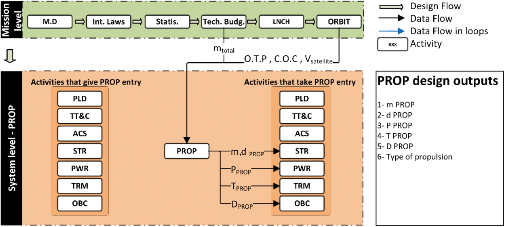
Figure 5: Flowchart of design activities for attitude control subsystem (ACS)
3.2.4 Activities for Structure and Mechanism Subsystem Design
The structure and mechanism subsystem are composed of two main parts. The first part is the main structure which is responsible for maintaining various subsystems in an appropriate place to satisfy the system level requirements. The second part is the mechanism of the antenna and solar arrays if necessary. The dimensions and geometry of the satellite are limited to available space in fairing. According to the requirements determined by the higher order activities and the requirements of the system level, the overall configuration and layout of the satellite is determined [35]. Mass parameters of satellite constellation such as the total mass of each satellite, center of mass position for each satellite, and moment of inertia should be calculated in this subsystem. Selection of appropriate material and design of the structure, as well as the establishment of the mechanical joint in order to connect and bear the loads, are the most important activities that should be performed in STR subsystem. Quasi-static load and vibrations applied from the launcher in different stages and phases are the most important parameters in the design of satellite structure. Other inputs of the structure and mechanism subsystem are the output of the technical characteristics, including the mass and total dimensions of the satellites. Also, after selecting the launcher, the operating frequencies produced by the launcher and the interface characteristics should be declared to the structure and mechanism subsystem. On the other hand, the design teams of all subsystems should report the mass and dimensions of the corresponding subsystem as well as technical requirements for the layout of each sub-system. For example, some subsystems have certain requirements such as certain temperature for their function or certain magnetic condition and etc. TT&C antennas and also inter-satellite link antennas have their own placement requirements [36]. Finally, the design team of the structure and mechanism subsystem should announce the final mass budget assigned to each sub-system. Also, the structural team should be reported the final total mass, final center of mass position and moment of inertia to the design team of attitude control subsystem. Another mission of the STR team is the design of proper mechanism with the considerable accuracy. This will be done with the joint collaboration of the structure and mechanism subsystem, and the ACS. The required accuracy for mechanisms is based on the necessity determined by mission level for the payload and telecommunication subsystem. Another important point about the design of the structure and mechanism subsystem is the attention to mission profile and events which is encountered during the time of construction and transportation, launch and when the satellites are placed in the network of the constellation. Considering the effects of shocks and vibrations produced by land transport, launcher, separation and the propulsion effect of the propulsion subsystem to place in the right position within the network of constellation and orbit modification, and also considering the effect of disturbances and atmospheric drag on structures and mechanisms are other issues that should be addressed to the mechanism subsystem design team [37,38]. Flowchart of activities in structure and mechanism subsystem is shown in Fig. 6.
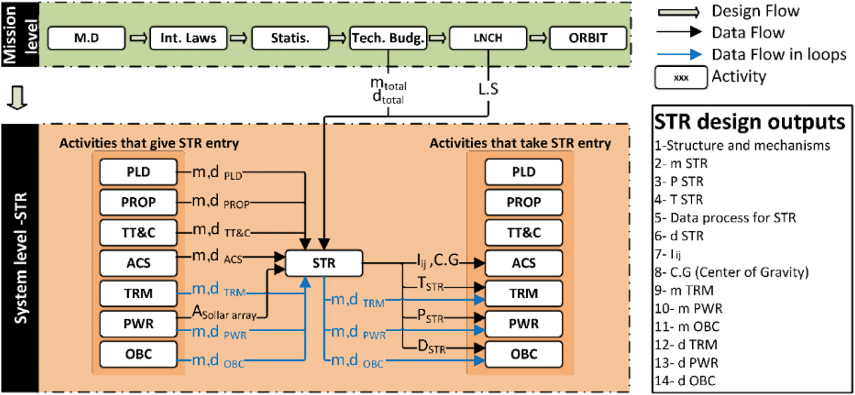
Figure 6: Flowchart of activities in structure and mechanism subsystem (STR)
3.2.5 Activities for Electric Power Supply Subsystem Design
Main tasks of electric power supply subsystem are supplying, storing and distributing power between satellite subsystems. The specification of this subsystem is determined with respect to different requirements, such as power consumption of each subsystem. Based on the total required power of the satellite, power subsystem dictates utilizing deployable solar arrays or installing solar arrays on the satellite body. Measurements associated with satellite batteries are also being used to provide solar eclipse orbit energy. Limitations of battery charging should be considered in solar array design. It is also necessary to design other relevant elements for energy dispensation in all electric, electronic and electromechanical (EEE) equipment. In this regard, designers of subsystems should announce the required power to the electric power supply subsystem, and eventually the power subsystem design team allocates power to each subsystem considering limitations and requirements. Power budget is one of the most important parameters that should be announced by the system engineering team to any of the subsystems as the starting point of design. But the basis for designing power subsystem is the values that are declared as the requirements of each subsystem. Eventually, this loop will be determined and finalized during the sessions of the system engineers and the power team [39]. Flowchart of design activities in electric power supply subsystem (PWR) is presented in Fig. 7.
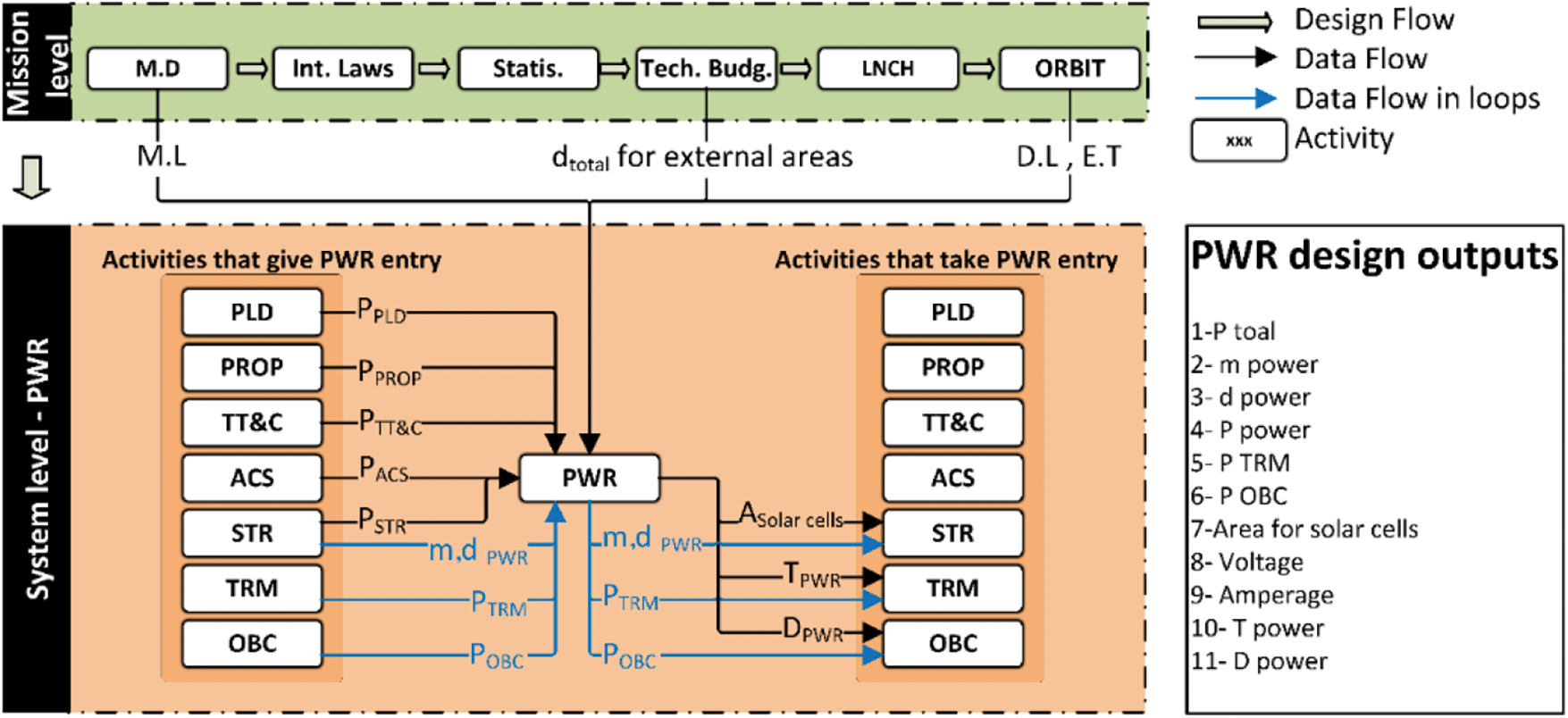
Figure 7: Flowchart of activities in electric power supply subsystem (PWR)
3.2.6 Activities for On-Board Computer Subsystem Design
The on-board computer (OBC) subsystem provides processing requirements, memory for storing telemetric data, and hardware interfaces for satellite equipment. In addition to mentioned tasks, this subsystem should send appropriate control commands to different subsystems based on planned mission [40]. To design this subsystem, design engineers in all subsystems must announce the amount of data processing in their subsystem to the on-board computer subsystem. OBC, like the other subsystems, will report generated heat, required power and mass to the corresponding subsystems. Flowchart of activities in OBC subsystem is illustrated in Fig. 8.

Figure 8: Flowchart of activities in the on-board computer subsystem (OBC)
3.2.7 Activities for Thermal Control Subsystem (TCS) Design
TCS satisfies temperature requirements for the optimal performance of each subsystem. The design inputs of this subsystem are the layout and optimum thermal condition for each subsystem, operating scenarios, power dissipation and heat generation in the subsystems. After thermal analysis, the thermal design of the satellite is provided and its considerations apply to the design of other subsystems. In this regard, all subsystems must declare their generated heat to TCS. Generally, calculation of heat in this subsystem should be done based on the power dissipation. On the other hand, the orbit and the condition of the satellites in space and the heat transfer to the environment is another source of production or loss of heat. The thermal control subsystem cooperates with structure and mechanism subsystem for layout of different subsystems [41,42]. Flowchart of activities in thermal control subsystem is presented in Fig. 9.
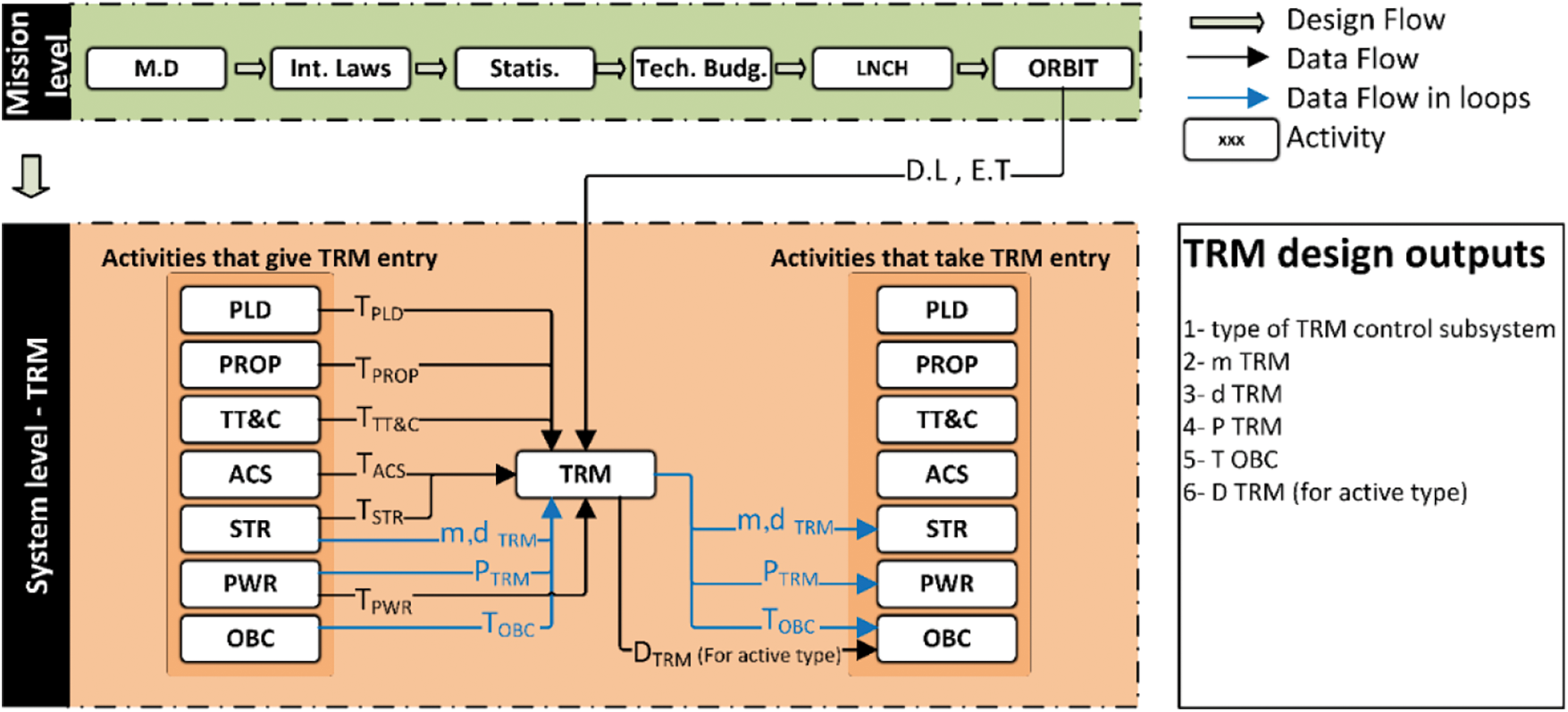
Figure 9: Flowchart of activities in thermal control subsystem (TCS)
The graph of links between the main activities that are being extracted from the above explanation has been presented in Fig. 10. Based on this figure, it is clear that exchanged parameters between two activities and two teams are not defined in this figure and just this figure determine exchanged information between two activities and teams. In other words, there is talk about the “existence” of data exchange and data flow but in Fig. 10, there is no discussion about exchanged parameters. In the design structure matrix (DSM) just the existence of exchange is important and exchanged parameters are not reported. Although, knowledge about exchanged parameters could be useful in design process and these parameters will be displayed in the final process.
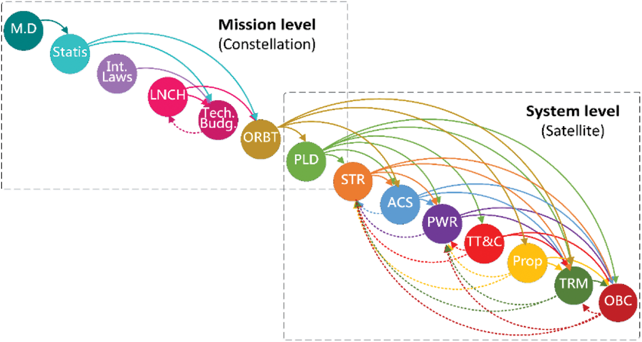
Figure 10: High-priority relationships between the main activities of the conceptual design of the constellation
4 Extracting Optimum Process and Relations between Activities
4.1 Design Structure Matrix (DSM) to Optimize Design Process
As mentioned in the previous sections, to achieve a system design process based on DSM, initially the design process should be broken into smaller activities. Then, the interfaces between different activities should be determined and design structure matrix should be formed based on the discovered interfaces. In this research, the process was divided into 15 main activities; based on sufficient knowledge of the system and mission profile of the satellite constellation, higher order interfaces were identified between the activities. Now, DSM could be set up for the 15 main activities based on discovered interfaces with the high priority level. The initial form of the design structure matrix (DSM) for LEO satellite constellations is illustrated in Fig. 11.
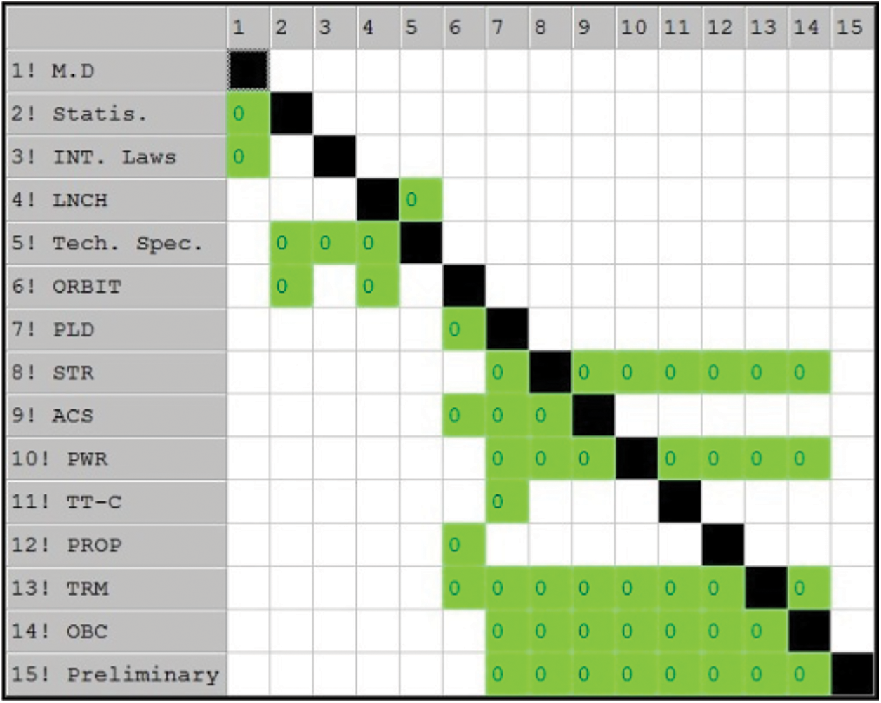
Figure 11: Initial form of DSM for conceptual design of the LEO satellite constellation
The optimized DSM is shown in Fig. 12. As explained earlier, the links shown in Fig. 10 indicate that each activity delivers at least one high priority data to another activity as an input. Based on Fig. 10, it could be concluded that the design loops are created between the technical specifications and the launcher selection. There are also design loops after the attitude control subsystem. The final results of DSM analysis and the final process extracted will be presented in the next section.
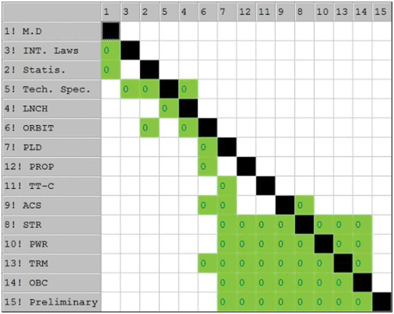
Figure 12: Optimized DSM for the conceptual design of the LEO satellite constellation
4.2 Extraction of the Design Process from DSM
Based on the optimized DSM (Fig. 12), the system design process of LEO satellite constellations has been presented in the conceptual design phase in accordance with Fig. 13.
This process represents the design path and the main design loops. This process is based on high priority links. In order to complete the design of the system in accordance with the purpose of this research, inputs and outputs of each step should be determined. Also, data flow between different working teams should be identified. This data flow is presented in Fig. 12. The mentioned figure has been set out in Section 3 and all links shown in this figure have been explained in Section 3. Based on this figure, the system is designed in accordance with the initial requirements. The design flow with the help of large arrows shows what the overall design process is and the data flow has been specified between the working teams. Note that the output of each team's activity as well as the necessary design elements will be determined at the conceptual design level of LEO satellite constellations.

Figure 13: The system design process for the Leo satellite constellation
In this section, to investigate the performance and capability of the proposed method in the optimal design process of satellite constellation, the results of this method are compared with the existing results in the literature. The conceptual design process for a satellite has been presented in [43]. The subsystem design procedure proposed in the a forementioned manuscript is as follows:
Payload, structure, attitude control, telecommunications, on-board computer, power supply and thermal control.
The interfaces shown in Fig. 10 will also be valid for the satellite under discussion in [43] (since the satellite class is the same). Thus, DSM can be inversely formed for the [43] with the same assumption of interfaces between subsystems in this research and the mentioned manuscript. In this regard, DSM is initially formed based on the interfaces between system elements and then optimized. The conceptual design processes of a satellite using DSM in [40] and our proposed method have been presented in Fig. 14. Comparison of two DSMs reveals that the numbers of unproduced design data, i.e., the marked elements above the main diagonal of DSM, have decreased significantly, which will lead to an agile design process.

Figure 14: Comparison of suggested conceptual design in this paper and [43]
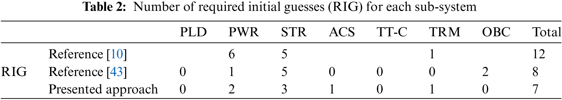
The same comparison can be performed for the other processes proposed presented in [10] as shown in Fig. 15A and the process proposed in this paper as displayed in Fig. 15B. Comparing these DSMs, 12 design requirements can be recognized for the lower levels which are not available in the DSM proposed of [10], while the number of unproduced design data in our presented procedure is seven.

Figure 15: Comparison of proposed conceptual design in this paper and [10]
For more clarification, the results reported in Figs. 14 and 15 have been tabulated in Table 2. As can be found from this table, the presented approach contains fewer loops.
In this research, design processes for LEO satellite constellations have been optimized based on a system engineering approach. Design structure matrix (DSM) is a powerful design tool for the system analysis. DSM has been used for optimizing the dependency of design parameters driving in the satellite conceptual design phase. The designed process was optimized by eliminating redundant loops and shortening design loops by relying on a systematic approach. The interfaces between parameters of the system in the proposed method were extracted by examining the life cycle of the product, carefully inspecting the mission profile, exploring the details of the “functions” and “activities” in the satellite constellation, as well as based on the formulation and computational relations, and the search for scientific resources plus the use of previous experiences. It was also attempted to reduce the complexity of the system by categorizing activities, creating and optimizing structures, assigning activities precisely and one-to-one to working teams, and specifying the flow of data. Finally, for investigating the performance and capability of the proposed method in the optimal design process of satellite constellation, the results of this method were compared with existing results in the literature. This comparison proved that the approach proposed in this paper reduced the cost and time of conceptual design process of a satellite constellation significantly.
Funding Statement: The authors received no specific funding for this study.
Conflicts of Interest: The authors declare that they have no conflicts of interest to report regarding the present study.
1. Teo, K. H., Tai, K., Schena, V., Simonini, L. (2021). An alternating renewal process to model constellation availability. Advances in Space Research, 68(9), 3717–3730. DOI 10.1016/j.asr.2021.06.047. [Google Scholar] [CrossRef]
2. Kannan, H., Mesmer, B. L., Bloebaum, C. L. (2017). Increased system consistency through incorporation of coupling in value-based systems engineering. Systems Engineering, 20(1), 21–44. DOI 10.1002/sys.21377. [Google Scholar] [CrossRef]
3. Song, Z., Chen, X., Luo, X., Wang, M., Dai, G. (2018). Multi-objective optimization of agile satellite orbit design. Advances in Space Research, 62(11), 3053–3064. DOI 10.1016/j.asr.2018.08.037. [Google Scholar] [CrossRef]
4. Wang, H., Li, H., Tang, C., Zhang, X., Wen, X. (2020). Unified design approach for systems engineering by integrating model-based systems design with axiomatic design. Systems Engineering, 23(1), 49–64. DOI 10.1002/sys.21505. [Google Scholar] [CrossRef]
5. Wilke, M., Quirmbach, O., Schiffner, M., Igenbergs, E. (2000). MuSSat-A tool for satellite design in concept design centers. Proceedings of EuSEC, pp. 337–344, Munich. [Google Scholar]
6. Ridolfi, G., Mooij, E., Corpino, S. (2009). A system engineering tool for the design of satellite subsystems. AIAA Modeling and Simulation Technologies Conference, pp. 6037, Chicago, Illinois. [Google Scholar]
7. Aas, C., Zandbergen, B. T., Hamann, R. J., Gill, E. K. (2009). SCALES: A system level tool for conceptual design of nano-and microsatellites. Small Satellites for Earth Observation, 7th International Symposium of the International Academy of Astronautics, pp. 4–8. Berlin, Germany. [Google Scholar]
8. Mirshams, M., Zabihian, E. (2019). FADSat: A system engineering tool for the conceptual design of geostationary Earth orbit satellites platform. Proceedings of the Institution of Mechanical Engineers, Part G: Journal of Aerospace Engineering, 233(6), 2152–2169. DOI 10.1177/0954410018773634. [Google Scholar] [CrossRef]
9. Fakoor, M., Ghoreishi, S. M. N., Sabaghzadeh, H. (2016). Spacecraft component adaptive layout environment (SCALEAn efficient optimization tool. Advances in Space Research, 58(9), 1654–1670. DOI 10.1016/j.asr.2016.07.020. [Google Scholar] [CrossRef]
10. Chang, Y. K., Hwang, K. L., Kang, S. J. (2007). SEDT (System Engineering Design Tool) development and its application to small satellite conceptual design. Acta Astronautica, 61(7–8), 676–690. DOI 10.1016/j.actaastro.2007.01.067. [Google Scholar] [CrossRef]
11. Steward, D. V. (1981). The design structure system: A method for managing the design of complex systems. IEEE Transactions on Engineering Management,28(3), 71–74. DOI 10.1109/TEM.1981.6448589. [Google Scholar] [CrossRef]
12. Browning, T. R. (2015). Design structure matrix extensions and innovations: A survey and new opportunities. IEEE Transactions on Engineering Management, 63(1), 27–52. DOI 10.1109/TEM.2015.2491283. [Google Scholar] [CrossRef]
13. Tompkins, Z., Grenn, M., Roberts, B. (2020). Improving system maturity assessments by incorporating a design structure matrix. IEEE Transactions on Engineering Management, 67(1), 122–140. DOI 10.1109/TEM.2018.2867440. [Google Scholar] [CrossRef]
14. Qian, Y., Lin, J., Goh, T. N., Xie, M. (2011). A novel approach to DSM-based activity sequencing problem. IEEE Transactions on Engineering Management, 58(4), 688–705. DOI 10.1109/TEM.2011.2107558. [Google Scholar] [CrossRef]
15. Browning, T. R. (2001). Applying the design structure matrix to system decomposition and integration problems: A review and new directions. IEEE Transactions on Engineering Management, 48(3), 292–306. DOI 10.1109/17.946528. [Google Scholar] [CrossRef]
16. Konstantinidis, E. I., Katsavounis, S., Botsaris, P. N. (2020). Design structure matrix (DSM) method application to issue of modeling and analyzing the fault tree of a wind energy asset. Wind Energy, 23(3), 731–748. DOI 10.1002/we.2454. [Google Scholar] [CrossRef]
17. Yassine, A., Dan, B. (2004). Complex concurrent engineering and the design structure matrix method. Concurrent Engineering, 11(3), 165–176.DOI 10.1177/106329303034503. [Google Scholar] [CrossRef]
18. Son, S., Kim, J., Ahn, J. (2017). Design structure matrix modeling of a supply chain management system using biperspective group decision. IEEE Transactions on Engineering Management, 64(2), 220–233. DOI 10.1109/TEM.2017.2657652. [Google Scholar] [CrossRef]
19. Kosari, A., Haji Jafari, M., Fakoor, M. (2016). On equivalency between numerical process DSM and state-space representation. IEEE Transactions on Engineering Management, 63(4), 404–413. DOI 10.1109/TEM.2016.2581166. [Google Scholar] [CrossRef]
20. Avnet, M. S., Weigel, A. L. (2010). An application of the design structure matrix to integrated concurrent engineering. Acta Astronautica, 66(5–6), 937–949. DOI 10.1016/j.actaastro.2009.09.004. [Google Scholar] [CrossRef]
21. Qiao, L., Ryan, M. (2015). Applying the design structure matrix (DSM) to SAR satellite formation flying design. Systems Engineering Test Evaluation Conference (SETE), Canberra. [Google Scholar]
22. Lee, J., Deng, W. Y., Lee, W. T., Lee, S. J., Hsu, K. H. et al. (2010). Integrating process and work breakdown structure with design structure matrix. Journal of Advanced Computational Intelligence and Intelligent Informatics, 14(5), 512–522. DOI 10.20965/jaciii.2010.p0512. [Google Scholar] [CrossRef]
23. Fakoor, M., Bakhtiari, M., Soleymani, M. (2016). Optimal design of the satellite constellation arrangement reconfiguration process. Advances in Space Research, 58(3), 372–386. DOI 10.1016/j.asr.2016.04.031. [Google Scholar] [CrossRef]
24. Wertz, J. R. (2009). Orbit & constellation design & management (second printing eds). USA: Microcosm, Inc. [Google Scholar]
25. Pardini, C., Anselmo, L. (2020). Environmental sustainability of large satellite constellations in low earth orbit. Acta Astronautica, 170(1), 27–36. DOI 10.1016/j.actaastro.2020.01.016. [Google Scholar] [CrossRef]
26. Schutz, B., Tapley, B., Born, G. H. (2004). Statistical orbit determination. USA: Academic Press. [Google Scholar]
27. Milani, A., Gronchi, G. (2010). Theory of orbit determination. UK: Cambridge University Press. [Google Scholar]
28. Courtney, W. F., Wiher, C. H. (1999). Satellite-based cellular telecommunications system utilizing an earth station subsystem. Google Patents. https://patents.google.com/patent/US5937352A/en. [Google Scholar]
29. Li, H., Zhang, Q., Zhang, N. (2009). Constructing space-based continuous navigation and communication system utilizing formation flying satellites on GEO orbit in deep space exploration. Acta Astronautica, 65(9–10), 1185–1189. DOI 10.1016/j.actaastro.2009.03.072. [Google Scholar] [CrossRef]
30. Ippolito, L. J. (2017). Satellite communications systems engineering. New York: Wiley Online Library. [Google Scholar]
31. Wertz, J. R. (2012). Spacecraft attitude determination and control. Germany: Springer Science & Business Media. [Google Scholar]
32. Fakoor, M., Amozegary, F., Bakhtiari, M., Daneshjou, k. (2017). Relative tracking control of constellation satellites considering inter-satellite link. Advances in Space Research, 60(9), 2021–2046. DOI 10.1016/j.asr.2017.07.012. [Google Scholar] [CrossRef]
33. Sarafin, T. P., Larson, W. J. (1995). spacecraft structures and mechanisms: From concept to launch. UK: Kluwer Academic Publishers. [Google Scholar]
34. Soleymani, M., Fakoor, M., Bakhtiari, M. (2019). Optimal mission planning of the reconfiguration process of satellite constellations through orbital maneuvers: A novel technical framework. Advances in Space Research, 63(10), 3369–3384. DOI 10.1016/j.asr.2019.02.003. [Google Scholar] [CrossRef]
35. Fakoor, M., Taghinezhad, M. (2016). Layout and configuration design for a satellite with variable mass using hybrid optimization method. Proceedings of the Institution of Mechanical Engineers, Part G: Journal of Aerospace Engineering, 230(2), 360–377. DOI 10.1177/0954410015591834. [Google Scholar] [CrossRef]
36. Fakoor, M., Zadeh, P. M., Eskandari, H. M. (2017). Developing an optimal layout design of a satellite system by considering natural frequency and attitude control constraints. Aerospace Science and Technology, 71(11), 172–188. DOI 10.1016/j.ast.2017.09.012. [Google Scholar] [CrossRef]
37. Wijker, J. J. (2008). Spacecraft structures. Germany: Springer Science & Business Media. [Google Scholar]
38. She, Y., Li, S., Li, Y., Zhang, L., Wang, S. (2019). Slew path planning of agile-satellite antenna pointing mechanism with optimal real-time data transmission performance. Aerospace Science and Technology, 90(4), 103–114. DOI 10.1016/j.ast.2019.04.028. [Google Scholar] [CrossRef]
39. Patel, M. R. (2004). Spacecraft power systems. USA: CRC Press. [Google Scholar]
40. Zhao, Y., Du, B., Li, S. (2020). Agile satellite mission planning via task clustering and double-layer tabu algorithm. Computer Modeling in Engineering & Sciences, 122(1), 235–257. DOI 10.32604/cmes.2020.08070. [Google Scholar] [CrossRef]
41. Gilmore, D. G., Donabedian, M. (2003). Spacecraft thermal control handbook. USA: American Institute of Aeronautics & Astronautics. [Google Scholar]
42. Karam, R. (1998). Satellite thermal control for systems engineers. USA: American Institute of Aeronautics and Astronautics. [Google Scholar]
43. Mirshams, M., Jafarsalehi, A. (2004). Surrogate model-based optimization of spacecraft design. Modares Mechanical Engineering, 14(13), 209–216. DOI 20.1001.1.10275940.1393.14.13.27.0. [Google Scholar]
 | This work is licensed under a Creative Commons Attribution 4.0 International License, which permits unrestricted use, distribution, and reproduction in any medium, provided the original work is properly cited. |