| Computer Modeling in Engineering & Sciences |
DOI: 10.32604/cmes.2022.019188
ARTICLE
An Experimental and Numerical Study on the Ballistic Performance of Multi-Layered Moderately-Thick Metallic Targets against 12.7-mm Projectiles
1School of Aeronautic Science and Engineering, Beihang University, Beijing, 100191, China
*Corresponding Authors: Mingjing Li. Email: limingjing@buaa.edu.cn; Leiting Dong. Email: ltdong@buaa.edu.cn
Received: 08 September 2021; Accepted: 08 November 2021
Abstract: The main goal of this work is to study the ballistic performance of multi-layered moderately-thick metallic targets. Several target configurations have been considered in this work, with various types of interlayer connection (spaced, contacted and adhesive) and the number of layers (four and eight), and the influence of target configurations on ballistic performance has been studied experimentally and numerically. In the experiments, the targets were impacted by 12.7-mm projectiles at a velocity around 820 m/s. The experimental results show that, with similar total thickness, the contacted and adhesive targets exhibit better ballistic performance than the monolithic targets, and the four-layered targets are better than the eight-layered targets with the same connection type. To explore the ballistic resistance mechanism, numerical method has been used to simulate the penetration process of each target. The numerical results indicate that petal formation and friction have significant influence on targets’ ballistic performance. Friction has stronger influence on the multi-layered targets than on the monolithic ones. According to the numerical results, about 14% of projectile's initial kinetic energy is dissipated by friction during penetrating the four-layered contacted target, which is proved to be the most effective type of target studied in this work. The results also indicate that, in contrast to common understanding, friction plays an important role even when the impact velocity is significantly higher than the ballistic limit. The outcome of this work may provide useful information for a better understanding of ballistic resistant mechanisms and more efficient utilization of multi-layered metallic targets in armor structural design.
Keywords: Multi-layered targets; 12.7-mm projectile; friction
In the past decades, multi-layered metallic plates have drawn broad attention for the usage in civil and military armored shields, and the ballistic performance of this kind of target has been studied intensively. Though armored shields are usually made of monolithic metallic plates, the demand for layered targets is increasing sharply, since it is normally difficult to manufacture monolithic metallic plates to the designed thickness [1], and properly designed multi-layered targets exhibit better ballistic performance compared to monolithic targets [2].
The idea of using multi-layered metallic targets is not new and their ballistic performance has been widely studied experimentally. Corran et al. [3] experimentally studied the ballistic performance of monolithic and layered targets using rounded-nose projectiles in the tests. They concluded that the multi-layered targets exhibit better ballistic performance, and the resistance mechanism is dominated by bending for monolithic targets and by membrane resistance for layered targets. Deng et al. [4] conducted comprehensive experiments to exam the ballistic behaviors of layered steel shields impacted by hemispherical-nosed projectiles. Their results showed that the monolithic shields exhibit higher ballistic limit velocity than the layered shields when the total thickness is relatively small, but this trend is reversed when the total thickness is above a specific value. The reason is that the targets’ failure mechanism is changed from mainly shearing to mainly bending and stretching when the thickness is increased. Dey et al. [2] performed experiments with monolithic steel shields and double-layered shields, with similar total thickness as 12 mm, impacted by blunt- and ogival-nose projectiles. They found that the double-layered targets exhibit better ballistic capacity against blunt-nose projectiles, but this advantage disappears for ogival-nose projectiles. Such phenomenon can be explained by the difference in resistance mechanisms. For blunt projectiles, targets’ failure modes are dominated by shear band for the double-layered targets and by ductile hole formation (DHF) for the monolithic targets. Differently, for ogival projectiles, targets’ failure modes are independent of target configurations and are dominated by DHF regardless. Similar phenomenon has also been reported and discussed in other literature [5–7].
Note that, in the research reviewed above, the targets were relatively thin compared to projectiles’ diameter, and projectiles’ velocity was lower than 500 m/s. To the authors’ knowledge, not much results can be found in the literature about the ballistic performance of moderately-thick layered targets impacted by projectiles at higher velocity and the existing results are to some extent incompatible [7]. According to numerical simulations by Abdelshafy et al. [8], two-or three-layered targets exhibit higher ballistic resistance than monolithic ones. Some other numerical and experimental studies show that monolithic targets are usually better than two-or three-layered targets [1,9–11]. Børvik et al. [12] concluded based on experimental observation that monolithic and double-layered targets have similar ballistic limit velocity, and Iqbal et al. [13] drew similar conclusion based on numerical simulations. Moreover, the understanding of layered targets’ ballistic mechanism is also not consistent. According to their numerical results, Iqbal et al. [13] found that the dominated failure mode of both monolithic and layered targets is DHF. But petal shape failure mode was observed by Børvik's group [12,14,15] in impact tests of layered targets. Obviously, conclusions drawn in these works are not consistent to some extent. Inspired by the contribution from the groups of Børvik et al. [12–15], the reason for the inconsistence may rely on the fact that the targets’ ballistic mechanism against ogive-nosed projectiles has not yet been clearly understood. Thus, thorough studies on the ballistic resistance mechanism of multi-layered moderately-thick targets are still needed to fully exploit the potential capacity of this type of armor structures, and how the interlayer connection and number of layers influence the targets’ ballistic performance is still an important question to be answered.
For above reason, this work aims on explore the ballistic performance of multi-layer moderately-thick targets based on impact experiments and simulations. In experiments, moderately-thick monolithic and multi-layered targets were impacted by 12.7-mm armor piercing (AP) projectiles at a velocity around 820 m/s. Different types of interlayer connection (spaced, contacted and adhesive) as well as the number of layers (four and eight) have been considered for the multi-layer targets. Numerical models were built according to the experimental setup in order to simulate the penetration process and to study the influence of target configurations on the ballistic performance.
This paper is organized in the following way. In Section 2, the setup of ballistic tests and experimental results are presented. In Section 3, numerical results are reported and compared with experimental observations. In Section 4, the influence of targets’ failure modes and configurations on the ballistic performance are discussed based on experimental and numerical results. In Section 5, main findings and contributions of this work are summarized.
The setup of ballistic tests in this work is shown in Fig. 1. A ballistic gun was used as the launcher. Standard 12.7-mm AP projectiles were used in this study. The type of projectiles has an ogival-shaped hard steel core, as shown in Fig. 2, with a mass of 29 g and a length of 51.6 mm. In the ballistic tests, the initial velocity was about 820 m/s. Impact velocity was calculated according to the time interval recorded by the time counter when the projectile went through the two pieces of tinfoil. The tested targets were constrained by confinement (see Fig. 3). Behind the confinement, there was an inhibiting device with a hole in the center. The inhibiting device determined the confinement displacement in the incident direction and allowed the residual projectiles to be arrested by the witness block. The witness block was made of 603 steel.
Figure 1: Setup of the ballistic tests
Figure 2: Hard steel core of a 12.7-mm AP projectile
Figure 3: (a) Confinement and (b) inhibiting devices used in the ballistic tests
The tested targets were made of 316L steel for which the yield stress is about 350 MPa. Three types of interlayer connection, i.e., spaced, contacted and adhesive, were considered for the multi-layered targets. In the spaced targets, there was a gap with constant width between neighboring layers. In the contacted targets, neighboring layers were in contact. In the adhesive targets, neighboring layers were glued using epoxy resin with specified thickness. The in-plane size of each target was 150 mm × 150 mm. The summed thickness of all steel plates in each target was about 40 mm. Note that the total thickness of the spaced and adhesive targets exceeded 40 mm since it consisted of the thickness of gaps or adhesive layers and the thickness of steel plates. In this work, the number of layers was chosen as four and eight for the multi-layer targets.
In the spaced targets, the gap between neighboring metallic plates was prescribed as 1 mm. The spaced targets were fixed by the confinement (see Fig. 3b), and the width of gaps was guaranteed by placing four iron wires, with a diameter of 1 mm, between neighboring layers (see Fig. 4). The contacted targets were prepared in a similar way without placing iron wires between layers. In the adhesive targets, the metallic layers were glued by 1 mm thick epoxy resin, which was SEIWON two-part epoxies. Similar to the spaced targets, the thickness of adhesive layers was guaranteed by using the iron wires. The glued targets were placed in air for more than 72 h until the epoxy resin was completely hardened. Figs. 5a and 5b show the adhesive targets with eight and four layers, respectively. Additionally, the monolithic targets with 40 and 60 mm thickness were also prepared and tested serving as references for the multi-layer targets.
Figure 4: Demonstration on the method to guarantee width of gaps or thickness of adhesive layers between neighboring metallic layers
Figure 5: Illustrative examples of the adhesive targets with (a) eight and (b) four layers
The target configurations used in this work are summarized in Table 1. The targets are labels in the following way. The monolithic targets are labelled by M, and the number before the dash indicates the total thickness of the targets and the number after refers to the sample number. For the multi-layered targets, the spaced, contacted and adhesive types are respectively labelled as S, C and A, and the number before the dash represents the number of layers and the one after is the sample number. In Table 1, the summed thickness of metallic plates (excluding thickness of gaps and adhesive layers) is also provided for each target.
In this work, residual depth of penetration (RDOP) is used to measure the ballistic performance of tested targets. RDOP was firstly proposed by Yaziv et al. [16] to measure the ballistic performance of ceramics and has also been used in other works [17,18]. The penetration depth in the semi-infinite 603 steel target was used as the reference (see Fig. 6a). In the original RDOP test, the ceramic tile was attached to the witness block. But, in this work, the witness block was placed 150 mm away from the tested targets to guarantee that the targets had enough space to deform during penetration. The ballistic performance of the tested targets was measured by the efficiency factor
where
Figure 6: Illustration of (a) reference, (b) RDOP and (c) DOP tests
Since, in our ballistic experiments, the 60-mm monolithic targets were not perforated completely in the tests, their ballistic performance was measured by depth of penetration (DOP), as shown in Fig. 6c, and the efficiency factor was calculated as
where
Since the adhesive targets consisted of metal and resin layers, the efficiency factor was calculated as
where
The experimental results are summarized in Table 2 including the penetration depth
The ballistic efficiency factor
Figure 7: The efficiency factor
It can be observed in Fig. 7 that efficiency factor
According to Fig. 8d, the dominated failure mode of the 60-mm monolithic targets (M60) was DHF. For such failure mode, the ogival-shaped projectiles induce localized plastic deformation in targets and leave hole-like impressions. During the penetration process, there is no material lost, and projectiles’ initial kinetic energy is mainly dissipated by plastic deformation.
Figure 8: Illustrative failure modes as (a) front side of M60, (b) front side of M40, (c) exit side of M40, (d) cross-section of M60, (e) cross-section of M40
As shown in Figs. 8b and 8e, the failure mode of the 40-mm monolithic targets (M40) was also dominated by DHF, but, since M40 was not thick enough to arrest the projectile, the targets were completely perforated, and petals were observed on the exit-side surface. In both the M60 and M40 cases, target material in impacted region was pushed and flowed outward from projectile nose during penetration process. In the M60 case, there was always sufficient material to impede the projectile (see Fig. 8d). In M40 case, when projectiles approached the red dash-dotted line in Fig. 8e, metal on the exit side of targets was fractured gradually leading to petal-shape failure mode (see Fig. 8c). According to Table 2, the efficiency factor
Compared to the monolithic targets, failure modes of the multi-layered targets were much more complicated (see Figs. 9–22) including DHF, petal formation, membrane stretching, bending, etc. Furthermore, as shown in Figs. 15–20, projectiles were fractured and stuck during penetrating some of the contacted and adhesive targets, which resulted in even more complicated ballistic mechanisms. Failure modes of the spaced, contacted and adhesive targets are discussed in the following.
Figure 9: The front side of each layer of eight-layered spaced targets
Figure 10: The exit side of each layer of eight-layered spaced targets
Figure 11: The front side of each layer of four-layered spaced targets
Figure 12: The exit side of each layer of four-layered spaced targets
Figure 13: The front side of each layer of eight-layered contacted targets
Figure 14: The exit side of each layer of eight-layered contacted targets
Figure 15: The front side of each layer of four-layered contacted targets
Figure 16: The exit side of each layer of four-layered contacted targets
Figure 17: The front side of each layer of eight-layered adhesive targets
Figure 18: The exit side of each layer of eight-layered adhesive targets
Failure modes of the spaced targets are illustrated in Figs. 9–12. For the eight-layered spaced targets, various failure modes, including DHF, petal formation, stretching, and bending, can be observed in Figs. 9 and 10. The evidence of DHF is the smooth hole surface observed in the Nos. 3, 4, 6, 7 layers in Fig. 10. Stretching and bending were also observed in Nos. 2, 3, 4, 6, 8 layers of the targets shown in Fig. 9. Note that photographs of Nos. 5 and 7 layers are not presented in Fig. 9 since their failure modes are similar to Nos. 4, 6, 8 layers. It is worthwhile to mention that petals with various shapes were observed in each layer of targets (Figs. 9 and 10). In Figs. 11 and 12, similar failure modes were observed for four-layered spaced targets and thus are not discussed in detail here.
For the contacted targets, similar pattern of failure modes was observed in Figs. 13–16 compared to the spaced targets (Figs. 9–12), but the petal formation was less severe in contacted targets. Moreover, as observed in Figs. 15 and 16, projectiles were fractured during perforating four-layered contacted targets, and projectile debris were arrested by the third layer of C4-1 target and the fourth layer of C4-2 target.
The failure modes of the adhesive targets are shown in Figs. 17–19 in which projectiles debris were arrested by the perforated targets. The projectiles were fractured into two pieces by the four-layered contacted targets (see Figs. 15 and 16), but, for the eight-layered adhesive case (see Fig. 20), projectiles were fragmented into several pieces. In the perforated eight-layered adhesive targets, debonding between layers was observed shown in Fig. 21. For the perforated eight-layered adhesive target, a fractured spherical piece of epoxy resin (see Fig. 22a), with a diameter of about 150 mm, was separated from the adjacent metal layers and was collected after the impact test. For the four-layered adhesive targets, the failure mode was different from those for the eight-layered adhesive case as follows. Firstly, projectiles were fractured during perforating both the eight-layered targets (see Figs. 17 and 18), but among the four-layered targets, the projectile perforating the A4-1 target was fractured and the one perforating the A4-2 target remained intact (see Fig. 19). Secondly, all metallic plates were separated in the four-layered targets after perforation (see Fig. 23) which was not the case for the eight-layered targets. Thirdly, a spherical region, with a diameter of about 30∼60 mm, of each adhesive layer in the A4-1 and A4-2 targets was crushed (see Fig. 22b) resulting in massive micro radial cracks, while the rest region remained bonded (see Nos. 1–2 of A4-1 and No. 1 of A4-2 in Fig. 19).
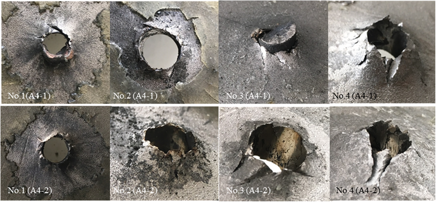
Figure 19: The exit side of each layer of the four-layered adhesive targets
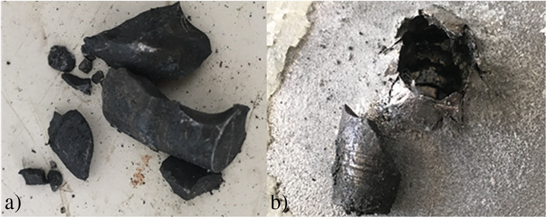
Figure 20: The fractured projectiles after perforating the eight-layered adhesive targets: (a) A8-1, (b) A8-2
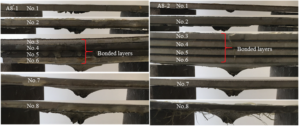
Figure 21: Failure mode of the eight-layered adhesive targets
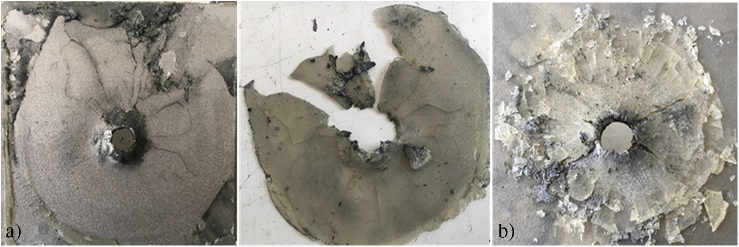
Figure 22: The failure modes of epoxy layers in the adhesive targets with (a) eight layers, (b) four layers
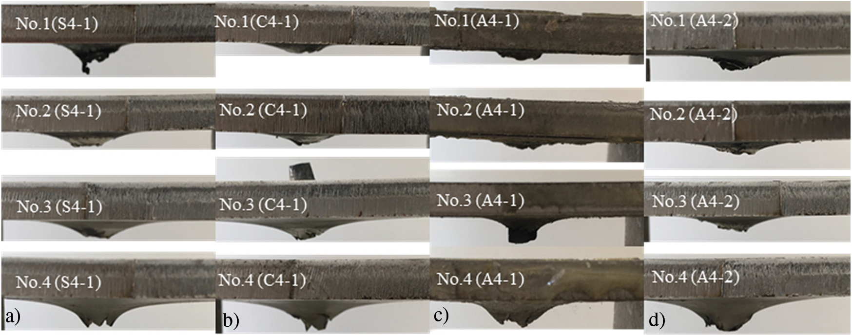
Figure 23: The failure modes of (a) spaced, (b) contacted, (c) and (d) adhesive targets with four layers
In the previous section, ballistic performance of several monolithic and layered metallic targets has been tested and the failure mode of each target has been discussed based on experimental results. However, in such high velocity impact tests, the penetration process can hardly be observed in detail which has hindered deeper understanding on the ballistic resistance mechanism of monolithic and layered targets. To overcome this restriction, numerical modeling has been employed to simulate the ballistic tests providing more information about the deformation and failure mechanisms of both targets and projectiles during penetration.
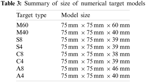
In this work, simulations of ballistic tests have been carried out using the commercial software LS-DYNA. Note that the thickness of tested targets was slightly different according to Table 1. Thus, target models were built using the real thickness to ensure the reliability of simulations. The size of all target models is summarized in Table 3. Based on symmetric consideration, only a quarter of the projectile-target model was built for each case to increase the computational efficiency. The distance between targets and witness was not considered in the numerical models for simplicity. Instead, projectile-target models and projectile-witness models were built separately. Projectile-target models were used firstly to determine the residual velocity of projectiles after perforation, and then projectile-witness models were used to determine the residual penetration depth.
As shown in Figs. 24 and 25, three-dimensional projectile-target models were built and discretized using finite elements and smoothed-particle hydrodynamics (SPH) particles. Since projectiles behave much stiffer than targets, projectile was modeled using eight-node hexahedron element with reduced integration, and hourglass control. 1377 elements were used in the projectile model illustrated in Fig. 24. Since severe localized deformation was experimentally observed in targets’ impacted region, discretizing the severely deformed region using finite elements may lead to large element distortion and unreasonable element erosion during impact simulations. Thus, an impacted zone was defined in the target model and was discretized using SPH particles. To increase computational efficiency, finite elements were used to discretize the non-impacted zone. A convergence study has been conducted determining the space size of SPH as 0.25 mm. The card of CONTACT_TIED_NODES_TO_SURFACE_OFFSET was used to couple the SPH with FEM by defining NODES and SURFACE. Here, the SPH particles near the surface were defined as the NODES, and the FEM surface was defined as SURFACE. An illustrative example of NODES and SURFACE defined in a projectile-target model is shown in Fig. 24. CONTACT_AUTOMATIC_NODES_TO_SURFACE was used to define the projectile-target contact behavior. Fig. 25 shows the assembled numerical models of monolithic, four-layered, and eight-layered targets.
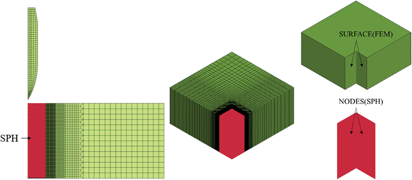
Figure 24: Illustrative projectile-target model with coupled SPH particles and finite elements
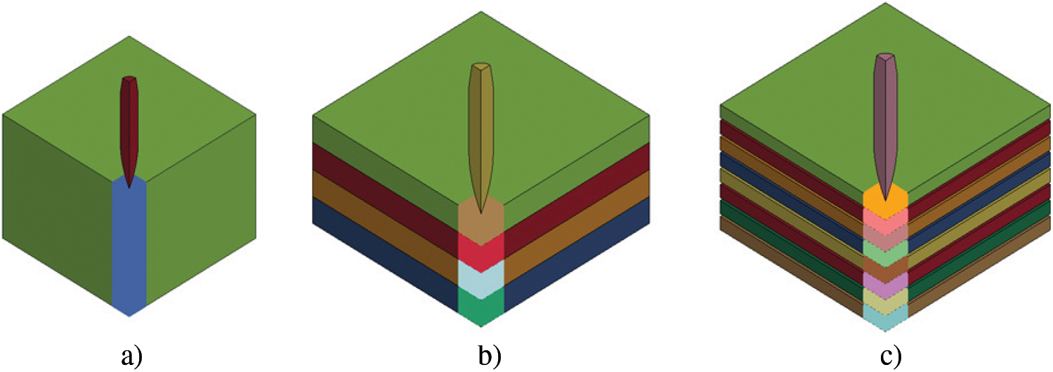
Figure 25: Illustrative projectile-target models for (a) monolithic, (b) four-layered and (c) eight-layered targets
In this work, the Johnson-Cook (JC) constitutive model was used for both projectiles and targets which is available in LS-DYNA as MATERIAL MODEL 15 [19]. The JC model can be expressed as
where
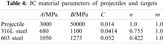
The JC parameters of 12.7-mm AP projectiles, adopted from literature [1], and the parameters of 316L steel and 603 steel, calibrated from Split Hopkinson Pressure Bar (SHPB) tests, were given in Table 4. The reference strain rate for 316L steel and 603 steel was taken as 2088 s−1 and 1842 s−1.
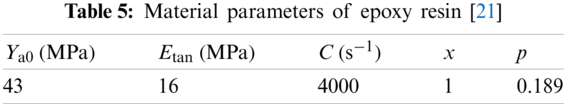
The Cowper-Symonds [20] equation was employed to define the constitutive behavior of epoxy resin reads,
where
Note that, for the impacted zone of targets, the failure strain was specified as 2.0 which has been verified as effective to prevent unreasonable erosion of SPH particles during penetration simulations. To validate the numerical model, numerical results of penetration simulations on the 60-mm monolithic steel targets have been compared with the experimental results and a good agreement was observed (see Fig. 26).
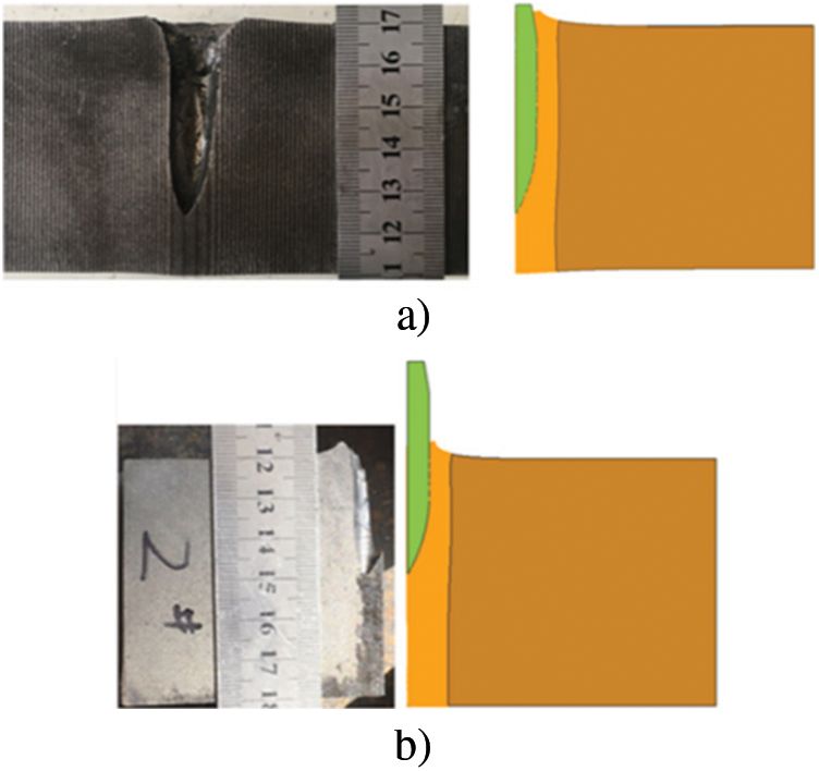
Figure 26: Experimental and numerical failure mode for (a) 316L steel and (b) 603 steel targets
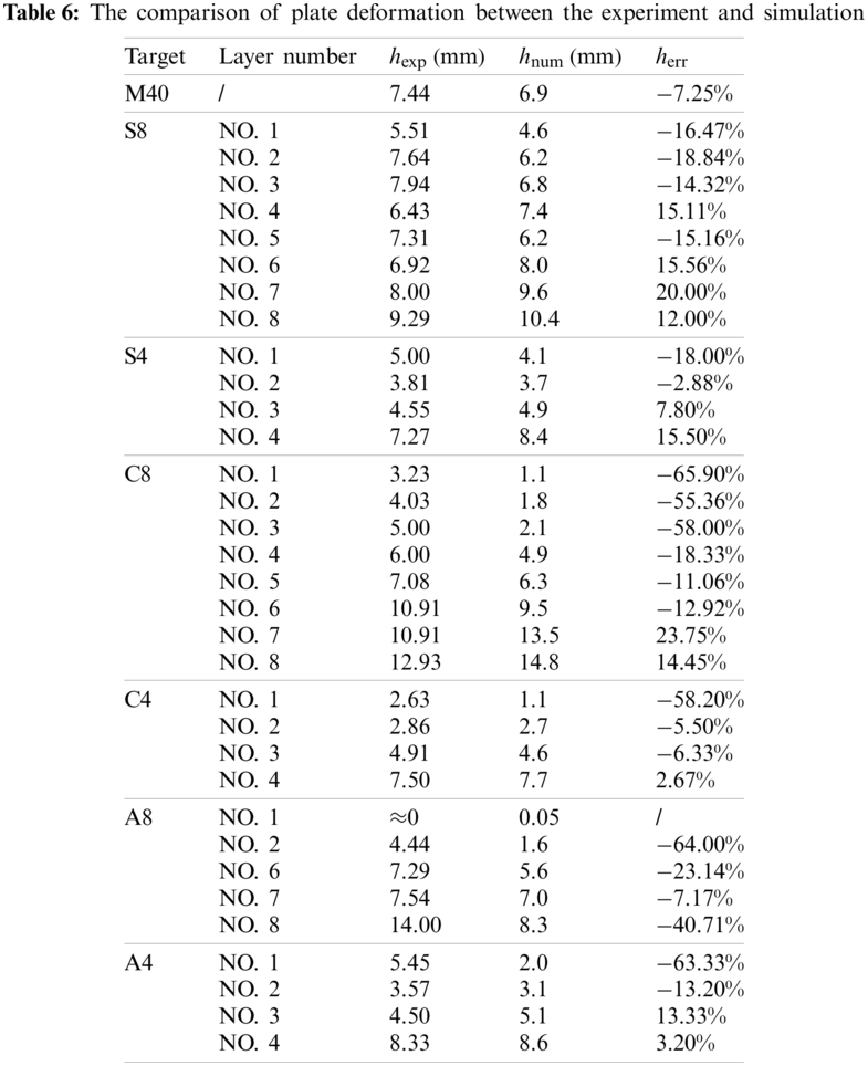
In this work, the maximum height of deformation h is defined to measure the deformation of impacted targets as shown in Fig. 27. Experimentally and numerically obtained maximum height of deformation,

Figure 27: Experimental parameters to describe the target deformation
However, the experimental and numerical residual depth of penetration in the witness block is inconsistent as summarized in Fig. 28. The residual depth of penetration of M40 is taken as a reference, marked by dashed lines in Fig. 28. Compared to experimental results, numerically-obtained residual depth was lower for 40-mm monolithic targets and higher for most multi-layered targets. Furthermore, it was observed in experiments that residual depth of some multi-layered targets, i.e., C4, A4 and A8, were lower than monolithic target M40, but, in numerical results, residual depth of multi-layered targets was always higher than monolithic case.
Figure 28: Comparison on residual penetration depth between experiments and simulations
In numerical simulations, petal-shape failure mode and friction were not considered which might be the reason for the mismatch between experimental and numerical results. In experiments (see Fig. 8e), petals were observed on the exit side of M40, which cannot be modeled by using the failure criterion with only constant failure strain in the impacted zone. To simulate petal formation, a potential crack zone was defined on the exit side of metallic plates (see Fig. 29), in which additional failure criterion needed to be applied. According to the experiment results in Fig. 8e, the thickness of the potential crack zone (labeled as h in Fig. 29a) has been prescribed as 5 mm for M40 and 2.5 mm for each layer of the multi-layered targets. Note that the potential crack zone was defined in each layer of the multi-layered targets, since petals have been experimentally observed in most layers of perforated targets as shown in Figs. 9–19. It is worth mentioning that petal formation in numerical simulations depended strongly on the failure criterion used in the potential crack zone. In this study, the JC damage model was used for simulation. In this model, the failure strain is defined as
where
reaches the value of 1. However, it is difficult to calibrate the damage parameters of 316L steel in experiments, since the failure behavior is influenced by many factors, such as stress triaxiality, strain rate, temperature, etc.
Figure 29: Illustration on (a) definition and (b) bottom view of the potential crack zone
Since petals have been observed in experiments indicating the importance of fracture in targets’ failure mechanism, potential crack zone was defined to simulate petal formation. Within the potential crack zone,
Figure 30: Comparison between illustrative example of experimental and numerical petal-shape failure modes of (a) front surface of M40, (b) the eighth layer of S8, (c) the eighth layer of A8
To study the influence of petal-shape failure mode and friction, numerical results are compared to the experimental results as summarized in Table 7. For the numerical results without friction, the residual penetration depth was remarkably larger when petals were considered. It indicates that the ballistic performance of both the monolithic and layered targets was weakened if petals were formed during penetration. The numerically-obtained residual depth for M40 was lower compared to experimental value as shown in Fig. 28, and the mismatch can also be explained by the lack of petal formation in numerical simulations. On the other hand, for the numerical results without petals, the residual penetration depth was smaller when friction was considered
Note that in Table 7,
Fig. 31 shows the change of projectiles’ kinetic energy with respect to time obtained from simulations. It can be observed that the projectiles’ kinetic energy was always dissipated faster when petal formation was considered. On the other hand, the projectiles’ kinetic energy was always dissipated faster when friction was considered. Thus, one can conclude that both petal formation and friction contribute on dissipating projectiles’ kinetic energy during the perforation process.
Figure 31: The curves of projectiles’ kinetic energy obtained from penetration simulations of targets with different configurations
Figs. 32 and 33 show the illustrative example of damage morphology for two different failure modes. As shown in Fig. 31, damage occurred locally near the projectile-target contact surface if the failure mode was dominated by DHF. In contrast, as shown in Fig. 31, damage appeared radially on the back of the target and the damage zone was enlarged gradually during the penetration when the failure mode was dominated by petal formation.
Figure 32: Damage morphology for the failure mode dominated by ductile hole formation
Figure 33: Damage morphology for the failure mode dominated by petal formation
Fig. 34 shows the stress-triaxiality field during the perforation of targets with various configurations obtained numerically. It was observed that the stress-triaxiality varied significantly with respect to target configurations and failure modes.
Figure 34: The stress-triaxiality during the perforation of different targets
As summarized in Table 7, the numerically-obtained residual penetration depth of C4 was 11.8 mm without considering petals, which was about 30% higher than the experimental value 8.05 mm. Since petals were observed in tested C4 targets (see Fig. 16), it's more reasonable to consider petals in numerical simulations by defining the potential crack zone as shown in Fig. 29. As summarized in Table 7, the consideration of petals resulted in significant increase on the numerical residual depth (from 11.8 to 15.2 mm), and the difference between numerical and experimental residual depth increased to 89%. Additionally, it was observed in experiments that the multi-layered contacted targets C4 and C8 exhibited better ballistic performance than monolithic targets M40, but this trend was reversed in numerical simulations that M40 was better than C4 and C8.
Friction may be one of the reasons for the inconsistence between experimental and numerical results. Without considering petals, the influence of friction has been studied numerically by means of penetration simulations with different projectile-target friction behavior (
The difference on projectiles’ kinematic energy dissipated by friction during penetration has been evaluated by the incremental rate of dissipated energy as
where
In previous section, friction has been numerically proved to be more important in multi-layered targets than in monolithic ones. Since similar friction coefficient has been used in simulations, the reason why friction has different effect on the ballistic resistance of multi-layered and monolithic targets might be related to the pressure acting on the projectile-target contact surface. Taken the 40-mm monolithic targets M40 and the four-layered contacted targets C4 as examples, in both cases the pressure was recorded for the same arbitrarily-chosen node on projectile surface (see Fig. 35), and it was observed that the pressure in the C4 case is higher than in the M40 case.
Figure 35: The pressure acting on projectile surface during penetrating M40 and C4
Since different deformation modes were observed in the perforated M40 and C4 targets (see Figs. 8e and 23b), the deformation modes were studied numerically to explain the different pressure on projectile surface for the M40 and C4 cases. For this purpose, x-displacement of nodes marked in Figs. 36a and 36c was plotted with respect to time in Figs. 36b and 36d.
Figure 36: x-displacement verse time curves for marked nodes with (a--b) for M40 and (c--d) for C4
For the M40 case, the nodes marked in Fig. 36a moved in the x+ direction until the maximum value was reached (see Fig. 36b). Since the failure mode of M40 is dominated by DHF as discussed in Section 2.4, the bullet hole was formed mainly due to plastic deformation and the diameter was almost unchanged after perforation. However, for the C4 case, x-displacement of the nodes marked in Fig. 36c increased firstly and decreased after reaching the maximum value according to Fig. 36d. It means the C4 targets behaved more elastically and the recovery of elastic deformation leaded to the decrease in the diameter of bullet hole. It was not the case for the M40 targets which deformed mainly plastically. According to the different deformation modes, one can conclude that pressure acting on the projectile-target interface is higher for the C4 case, and thus friction plays a more important role.
The projectiles collected after perforating M40 and C4 were shown in Fig. 37. It was observed that the projectile surface in Fig. 37b for C4 was rougher than that in Fig. 37a for M40, which also indicated that friction played more important role in the C4 case. Note that the friction coefficient varies during the penetration process [23], but, for simplicity, a constant value has been used in this work, since we mainly aimed at a qualitative study on the influence of friction on targets’ ballistic performance.
Figure 37: (a) Smooth projectile surface for M40, (b) coarse projectile surface for C4
To the authors’ knowledge, friction has been considered as significant only at an impact velocity closed to the ballistic limit velocity in existing research [15,23–28]. In contrast to the common understanding, it has been proved in this work that friction is also significant for four-layered contacted and adhesive targets impacted by projectiles at a velocity (820 m/s) much higher than the ballistic limit. This new finding provides useful information to understand the ballistic resistance mechanism of multi-layered metallic targets.
4.2 Effect of Interlayer Connection Type
For the multi-layered targets tested in this work, it is straightforward to come up with the idea that the interlayer connection should has influence on ballistic performance. As discussed above, targets exhibit weaker ballistic performance if petals are formed during perforation. Since petals are induced because of cracks on the exit side of metallic layers, the correlation between the types of interlayer connection and the number of cracks observed in experiments has been studied. As summarized in Table 9, the use of contacted and adhesive connection leaded to less cracks as well as smaller residual penetration depth in both four- and eight-layered targets. This is because, for these two types of connection, the deformation of perforated layers is restricted due to the strong support provided by residual layers. In contrast, for the spaced targets, perforated layers are easier to deform due to the lack of interlayer support, which results in more cracks in failure mode and weaker ballistic performance (see Table 9). This finding agrees with the discussion in Section 3.2 that targets’ ballistic resistance is weakened if petal formation is considered and more petals results in poorer ballistic performance.
To explore the mechanism how ballistic performance is influenced by petal formation, pressure between projectiles and targets, numerically obtained at the same node of projectile surface, is compared in Fig. 38 for the C4 model with/without petals and the S4 model with petals. The pressure obtained in the C4 model without petals was much higher than in the C4 model with petals. It can be concluded based on Fig. 38 that petal formation results in lower projectile-target pressure. Since friction is related to pressure, it can also be concluded that petal formation results in lower friction and consequently weaker ballistic performance. Note that not much petals were observed in the perforated C4 targets in experiments, thus it is more reasonable to compare results from the C4 model without petal and the S4 model with petals. According to Fig. 38, it is obvious that the pressure acting the C4 model with petal is much higher than the S84 case, so one can conclude that the improvement of ballistic performance due to friction is more significant for C4 targets compared to S4 targets.
Figure 38: The pressure acting on the projectile surface for C4 and S4
Among the four-layered targets, the least petals were observed in the C4 targets, and it can be inferred that the friction plays more important role in this case according to above discussion. This speculation is supported by the experimental observation that the projectiles was stuck in the C4 targets as shown in Figs. 15 and 16. Similar results were also observed in the perforated adhesive targets. Considering the two tested targets for A4, though similar configuration was used, less cracks were observed in A4-1 than in A4-2 (see Fig. 24), and thus stronger friction is inferred in A4-1. This speculation is also proved by experimental observation that the projectile was stuck in A4-1 and it was not the case for A4-2.
Taken the C4 targets, which is the best configuration studied in this work, as an example, the contribution of friction has been studied numerically. In experiments, projectiles were fractured during perforating the C4 targets, and a debris, stuck in a C4 target shown in Fig. 39, had a length of 20.1 mm and a weight of 7.3 g. To calculate the residual velocity of the debris after perforating the target, simulations were conducted in which the witness was impacted by either an intact projectile or a projectile debris with a length of 20.1 mm at various initial velocities. Fig. 40 demonstrates a linear relationship between the initial impact velocity
Figure 39: Comparison between the fractured projectile and the intact projectile
Figure 40: The penetration depth vs. the impact velocity for projectile-witness simulations
Based on the lines in Fig. 40, the residual velocity
In Table 11,
4.3 Effect of the Layer Number
Beside the types of interlayer connection, the number of layers may also influence the ballistic performance of multi-layered targets. In experiments, petals were observed in each layer of perforated targets, and thus the increase in number of layers resulted in more plates where petals can be induced. In Fig. 41, the number of cracks observed in tested targets is summarized with respect to number of layers. For each type of connection, more cracks were observed in the eight-layered targets than in the four-layered ones, and the most significant difference was observed among the contacted targets is the number of cracks observed in the C8 targets was 340% percent higher than in the C4 targets.
Figure 41: The number of cracks experimentally observed in the perforated targets
Since the total thickness of metallic layers was similar for all target configurations used in this work, more layers leaded to thinner single layer. During perforation, thinner metallic plates are easier to be deformed, and thus cracks are easier to be induced. This conclusion agrees with the experimental observation that larger deformation and more petals were observed in the eight-layered targets than in the four-layered targets. This explained why, with similar total thickness, the targets with more layers exhibited worse ballistic performance.
In this work, the ballistic performance of multi-layered and monolithic targets with moderate thickness has been studied experimentally and numerically. The targets were impacted by 12.7-mm AP projectiles at a relatively high velocity (about 820 m/s). Six different considerations have been considered for multi-layered targets, which were spaced, contacted and adhesive targets with four or eight layers. The ballistic efficiency factor has been defined, based on RDOP test results, to evaluate the ballistic performance of the tested targets. Based on the experimental and numerical results obtained in this work, the following conclusions can be drawn:
(1) Taking monolithic targets as a reference, the use of some multi-layered configurations results in better ballistic performance, i.e., four-/eight-layered contacted/adhesive targets. Among them, a four-layered contacted target is the best configuration in which the efficiency factor is increased by about 20% compared to monolithic targets.
(2) Projectile-target friction plays an important role in ballistic resistance mechanism of multi-layered targets at an impact velocity (about 820 m/s) much higher than the ballistic limit. Taking the four-layered contacted target as an example, numerical results show that at least 14% of projectiles’ initial kinetic energy is dissipated by friction during perforation.
(3) The ballistic performance of the moderately-thick multi-layered targets is significantly weakened if petals are induced during perforation. Numerical results show that pressure between projectiles and targets is lower when petals are induced which results in weaker projectile-target friction. This is one reason why petal formation influences ballistic performance, since friction enhances targets’ ballistic resistance as concluded above.
(4) The interlayer connection significantly influences targets’ ballistic performance. Among four-layered targets, the use of contacted connection results in fewer petals and better ballistic performance, and among eight-layered targets, adhesive connection is the best configuration. Spaced connection is the worst configuration for both four- and eight-layered targets due to the lack of support between layers.
(5) When the total target thickness is consistent, more layers result in worse ballistic performance, since more layers are involved where petals can be induced. Also, more layers lead to thinner single layers, and thus the layers are easier to deform and petals are easier to be induced.
The above results provide useful information for a better understanding of ballistic resistance mechanism of multi-layered moderately-thick metallic targets against high velocity 12.7 mm AP projectiles, which, to the authors’ knowledge, haven't been thoroughly studied. The outcome helps to fully exploit the potential capacity of such kind of targets and can serve as a valuable reference for armor structural design.
Acknowledgement: The authors acknowledge the support of the National Natural Science Foundation of China. The editor and both reviewers are also gratefully acknowledged.
Funding Statement: This work was supported by the National Natural Science Foundation of China [Grant Nos. 12102023 and 12072011].
Conflicts of Interest: The authors declare that they have no conflicts of interest to report regarding the present study.
1. Flores-Johnson, E. A., Saleh, M., Edwards, L. (2011). Ballistic performance of multi-layered metallic plates impacted by a 7.62-mm APM2 projectile. International Journal of Impact Engineering, 38(12), 1022–1032. DOI 10.1016/j.ijimpeng.2011.08.005. [Google Scholar] [CrossRef]
2. Dey, S., Børvik, T., Teng, X., Wierzbicki, T., Hopperstad, O. S. (2007). On the ballistic resistance of double-layered steel plates: An experimental and numerical investigation. International Journal of Solids and Structures, 44(20), 6701–6723. DOI 10.1016/j.ijsolstr.2007.03.005. [Google Scholar] [CrossRef]
3. Corran, R. S. J., Shadbolt, P. J., Ruiz, C. (1983). Impact loading of plates—An experimental investigation. International Journal of Impact Engineering, 1(1), 3–22. DOI 10.1016/0734-743X(83)90010-6. [Google Scholar] [CrossRef]
4. Deng, Y., Zhang, W., Cao, Z. (2012). Experimental investigation on the ballistic resistance of monolithic and multi-layered plates against hemispherical-nosed projectiles impact. Materials & Design, 41, 266–281. DOI 10.1016/j.matdes.2012.05.021. [Google Scholar] [CrossRef]
5. Alavi Nia, A., Hoseini, G. R. (2011). Experimental study of perforation of multi-layered targets by hemispherical-nosed projectiles. Materials & Design, 32(2), 1057–1065. DOI 10.1016/j.matdes.2010.07.001. [Google Scholar] [CrossRef]
6. Gupta, N., Iqbal, M., Sekhon, G. (2008). Effect of projectile nose shape, impact velocity and target thickness on the deformation behavior of layered plates. International Journal of Impact Engineering, 35(1), 37–60. DOI 10.1016/j.ijimpeng.2006.11.004. [Google Scholar] [CrossRef]
7. Ben-Dor, G., Dubinsky, A., Elperin, T. (2017). New results on ballistic performance of multi-layered metal shields: Review. Theoretical and Applied Fracture Mechanics, 88, 1–8. DOI 10.1016/j.tafmec.2016.11.002. [Google Scholar] [CrossRef]
8. Abdelshafy, M., Oyadiji, S. (2007). Penetration behaviour of steel plates. ASME 2007 International Design Engineering Technical Conferences and Computers and Information in Engineering Conference, Nevada, USA. [Google Scholar]
9. Copland, A., Scheffler, D. (2003). Influence of air gaps onlong rod penetrators attacking multi-plate target arrays. Army Research Lab Aberdeen Proving Ground MD. [Google Scholar]
10. Flis, L., Sperski, M. (2013). An investigation of the resistance of multi-layered ships steel shields to 12.7 mm projectiles. Scientific Journal of Polish Naval Academy, 4(195), 31–49. DOI 10.5604/0860889x.1097962. [Google Scholar] [CrossRef]
11. Iqbal, M., Gupta, P., Deore, V., Tak, S., Tiwari, G. et al. (2012). Effect of target span and configuration on the ballistic limit. International Journal of Impact Engineering, 42, 11–24. DOI 10.1016/j.ijimpeng.2011.10.004. [Google Scholar] [CrossRef]
12. Børvik, T., Dey, S., Clausen, A. (2009). Perforation resistance of five different high-strength steel plates subjected to small-arms projectiles. International Journal of Impact Engineering, 36(7), 948–964. DOI 10.1016/j.ijimpeng.2008.12.003. [Google Scholar] [CrossRef]
13. Iqbal, M. A., Chakrabarti, A., Beniwal, S., Gupta, N. K. (2010). 3D numerical simulations of sharp nosed projectile impact on ductile targets. International Journal of Impact Engineering, 37(2), 185–195. DOI 10.1016/j.ijimpeng.2009.09.008. [Google Scholar] [CrossRef]
14. Børvik, T., Hopperstad, O. S., Berstad, T., Langseth, M. (2002). Perforation of 12 mm thick steel plates by 20 mm diameter projectiles with flat, hemispherical and conical noses: Part II: Numerical simulations. International Journal of Impact Engineering, 27(1), 37–64. DOI 10.1016/S0734-743X(01)00035-5. [Google Scholar] [CrossRef]
15. Børvik, T., Langseth, M., Hopperstad, O., Malo, K. (2002). Perforation of 12 mm thick steel plates by 20 mm diameter projectiles with flat, hemispherical and conical noses: Part I: Experimental study. International Journal of Impact Engineering, 27(1), 19–35. DOI 10.1016/S0734-743X(01)00034-3. [Google Scholar] [CrossRef]
16. Yaziv, D., Rosenberg, G., Partom, Y. (1986). Differential ballistic efficiency of applique armor. Proceedings on the 9th International Symposium on Ballistics, Shrivenham, UK. [Google Scholar]
17. Crouch, I. (2016). The science of armour materials. UK: Woodhead Publishing. [Google Scholar]
18. Li, J., Zhang, L., Huang, F. (2016). Experiments and simulations of tungsten alloy rods penetrating into alumina ceramic/603 armor steel composite targets. International Journal of Impact Engineering, 101, 1–8. DOI 10.1016/j.ijimpeng.2016.09.009. [Google Scholar] [CrossRef]
19. Halquist, J. O. (2007). LS-DYNA keyword user’s manual version 971. California: Livermore Software Technology Corporation. [Google Scholar]
20. Grouch, I., Greaves, L., Ruiz, C., Harding, J. (1994). Dynamic compression of toughened epoxy interlayers in adhesively bonded aluminium laminates. Journal de Physique IV France, 4, C8-201–C8-206. DOI 10.1051/jp4:1994829. [Google Scholar] [CrossRef]
21. Zaera, R., Sánchez-Sáez, S., Pérez-Castellanos, J., Navarro, C. (2000). Modelling of the adhesive layer in mixed ceramic/metal armours subjected to impact. Composites Part A: Applied Science and Manufacturing, 31(8), 823–833. DOI 10.1016/S1359-835X(00)00027-0. [Google Scholar] [CrossRef]
22. Ren, B., Li, S. (2010). Meshfree simulations of plugging failures in high-speed impacts. Computers & Structures, 88(15), 909–923. DOI 10.1016/j.compstruc.2010.05.003. [Google Scholar] [CrossRef]
23. Rosenberg, Z., Vayig, Y. (2020). On the friction effect in the perforation of metallic plates by rigid projectiles. International Journal of Impact Engineering, 149, 103794, DOI 10.1016/j.ijimpeng.2020.103794. [Google Scholar] [CrossRef]
24. Woodward, R. (1978). The penetration of metal targets by conical projectiles. International Journal of Mechanical Sciences, 20(6), 349–359. DOI 10.1016/0020-7403(78)90038-3. [Google Scholar] [CrossRef]
25. Zaid, A., El-Kalay, A., Travis, F. (1973). An examination of the perforation of a mild steel plate by a flat-ended cylindrical projectile. International Journal of Mechanical Sciences, 15(2), 129–143. DOI 10.1016/0020-7403(73)90061-1. [Google Scholar] [CrossRef]
26. Holmen, J. K., Hopperstad, O. S., Børvik, T. (2017). Influence of yield-surface shape in simulation of ballistic impact. International Journal of Impact Engineering, 108, 136–146. DOI 10.1016/j.ijimpeng.2017.03.023. [Google Scholar] [CrossRef]
27. Rosenberg, Z., Forrestal, M. (1988). Perforation of aluminum plates with conical-nosed rods—Additional data and discussion. Journal of Applied Mechanics, 55(1), 236. DOI 10.1115/1.3173639. [Google Scholar] [CrossRef]
28. Børvik, T., Forrestal, M., Warren, T. (2010). Perforation of 5083-H116 aluminum armor plates with ogive-nose rods and 7.62 mm APM2 bullets. Experimental Mechanics, 50(7), 969–978. DOI 10.1007/s11340-009-9262-5. [Google Scholar] [CrossRef]
 | This work is licensed under a Creative Commons Attribution 4.0 International License, which permits unrestricted use, distribution, and reproduction in any medium, provided the original work is properly cited. |