| Computer Modeling in Engineering & Sciences |
DOI: 10.32604/cmes.2022.017533
ARTICLE
Range-Only UWB SLAM for Indoor Robot Localization Employing Multi-Interval EFIR Rauch-Tung-Striebel Smoother
1Qingdao Branch of Naval Aviation University, Qingdao, 266000, China
2School of Electrical Engineering, University of Jinan, Jinan, 250022, China
3Shandong Beiming Medical Technology Co., Ltd., Jinan, 250022, China
*Corresponding Author: Yuan Xu. Email: xy_abric@126.com
Received: 18 May 2021; Accepted: 11 August 2021
Abstract: For improving the localization accuracy, a multi-interval extended finite impulse response (EFIR)-based Rauch-Tung-Striebel (R-T-S) smoother is proposed for the range-only ultra wide band (UWB) simultaneous localization and mapping (SLAM) for robot localization. In this mode, the EFIR R-T-S (ERTS) smoother employs EFIR filter as the forward filter and the R-T-S smoothing method to smooth the EFIR filter's output. When the east or the north position is considered as stance, the ERTS is used to smooth the position directly. Moreover, the estimation of the UWB Reference Nodes’ (RNs’) position is smoothed by the R-T-S smooth method in parallel. The test illustrates that the proposed multi-interval ERTS smoothing for range-only UWB SLAM is able to provide accurate estimation. Compared with the EFIR filter, the proposed method improves the localization accuracy by about 25.35% and 40.66% in east and north directions, respectively.
Keywords: Robot localization; ultra wide band; Rauch-Tung-Striebel smoother; extended FIR filter
In recent years, the mobile robots have been widely used in the medical field [1,2]. Especially affected by the COVID-19 more and more jobs in hospitals require mobile robots to replace doctors, which provides the demand for indoor localization of mobile robots in indoor environment. However, there are challenges in the research of mobile robot localization for indoor environment [3,4].
To the mobile robot localization, the global navigation satellite system (GNSS) has been proposed and widely used [5,6]. For instance, in [7], the global positioning system (GPS)-based approach has been widely used in the small mobile robot. the GPS has been used to assist the simultaneous localization and mapping (SLAM) for mobile robot [8]. In [9], the GPS/BeiDou integrated navigation satellite system (BDS) has been proposed. It should be emphasized that although localization method based on the GNSS can provide the position information, this method still have shortcomings:
• The localization accuracy is meter-lever, which is not suitable for indoor localization.
• In the indoor environment, the GNSS signal may be outage.
In order to overcome these shortcomings, there are many attempts. For instance, some existing research proposes to use radio frequency identification based scheme (RFID) which has been investigated for indoor robot localization [10,11]. Moreover, the RFID is also been used in moving object localization [12]. A new method of RFID system has been developed for localizing mobile robot employing configures reader (antenna) [13]. In [14], the WiFi has been used in mobile robot positioning. Noted that both the RFID and the WiFi are able to provide the position information in indoor environment, the localization accuracy of the RFID and the WiFi is not suitable for the high precision indoor mobile robot localization [15]. In order to provide more accurate localization information, the localization scheme employing ultra wide band (UWB) has been proposed [16]. For example, in [17] and [16], the UWB is used to measure the mobile robot's position. It should be emphasized that the localization scheme using UWB improves the positioning accuracy.
Based on the localization method, the data fusion method is investigated. For example, the Kalman filter (KF) is used to fuse the data of the laser range finder (LRF) sensor for the mobile robot [18,19]. In order to face the nonlinear system, the extended KF (EKF) filter is proposed for the indoor localization of a mini unmanned air vehicle (UAV) based on low-cost inertial measurement unit (IMU)/UWB/Vision [20]. The improved cubature Kalman filter for GNSS/INS using transformation of posterior sigma-points error is investigated [21]. In [22], the vehicular INS/GPS-integration system based on the unscented KF UKF is derived. The cubature KF is designed for GNSS/INS under GNSS-challenged environment in [23]. One can infer that the Kalman filter is sensitive to the noise initial value and noise statistics, which is hard to obtain in real-time localization [18]. In order to improve the robustness of the localization, the unbiased finite impulse response (UFIR) filter is proposed [24]. For example, in [25], an adaptive-horizon iterative UFIR filter is derived. the FIR filter is employed for the RFID localization [26]. Moreover, in order to improve the localization accuracy, the Rauch-Tung-Striebel (R-T-S) smoother is proposed. for example, in [27], the ensemble Kalman smoother is designed for indoor mobile robot.
For improving the localization accuracy, this work proposes a multi-interval extended finite impulse response (EFIR) R-T-S smoother for the indoor robot's range-only ultra wide band (UWB) simultaneous localization and mapping (SLAM), which employs EFIR filter as the forward filter and the R-T-S smoothing method to smooth the EFIR filter's estimation of the east position, north position, and the UWB Reference Node (RN)'s position, respectively.
The contribution of this work resides in the following:
• A range-only UWB SLAM scheme is designed for indoor robot.
• A new ERTS smoothing algorithm employs the EFIR filter as the forward filtering and the R-T-S smoothing as the backward smoothing method is proposed.
• A new smoothing scheme is proposed for the estimation of the east position, north position, and the UWB RN's position, respectively.
2 The Data Fusion Model for Range-Only UWB SLAM for Robot Localization
In this section, the robot localization scheme for fusing the range-only UWB measurements will be designed firstly. Then, the data fusion model based on the range-only UWB SLAM scheme will be investigated.
2.1 The Scheme for Fusing the Range-Only UWB Measurements
Fig. 1 displays the structure of the scheme for fusing the range-only UWB measurements. In this work, the UWB localization system includes 4 reference nodes (RNs) and one blind node (BN). The RNs are pre-positioned on static coordinates, and the BN is fixed on the robot. When the UWB localization system works, BN is used to collect the ranges
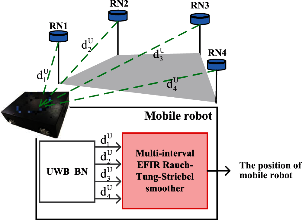
Figure 1: Range-only UWB measurements fusion structure
2.2 The Localization Model for the Data Fusion Filter
In this subsection, the localization model for the data fusion filter for the model mentioned in Section 2.1 will be investigated. The state equation can be written as Eq. (1).
where the time index is expressed in l,
where
where the items xl, yl,Vxl,Vyl is the robot's position in east directions, the robot's position in north, the robot's velocity in east and the robot's velocity in north directions at the index l for time, the
where the Δl is the sampling interval.
The measurement equation for the data fusion filter is listed in Eq. (5).
where the
3 The Multi-Interval EFIR Rauch-Tung-Striebel Smoother
In this section, the multi-interval ERTS smoother will be designed based on the models (1) and (5). The multi-interval ERTS smoother consists of forward filtering and backward smoothing, consequently, we will design the UFIR filter and the R-T-S smoother based on the models (1) and (5), secondly, the online multi-interval R-T-S smoothing scheme will be investigated.
In the multi-interval ERTS smoother, the EFIR filter is employed as the forward filtering algorithm of the EFIR R-T-S smoother. The EFIR filter algorithm for the models (1) and (5) is sketched in Algorithm 1. We can infer that the performance of the EFIR filter depends on the size ME of the
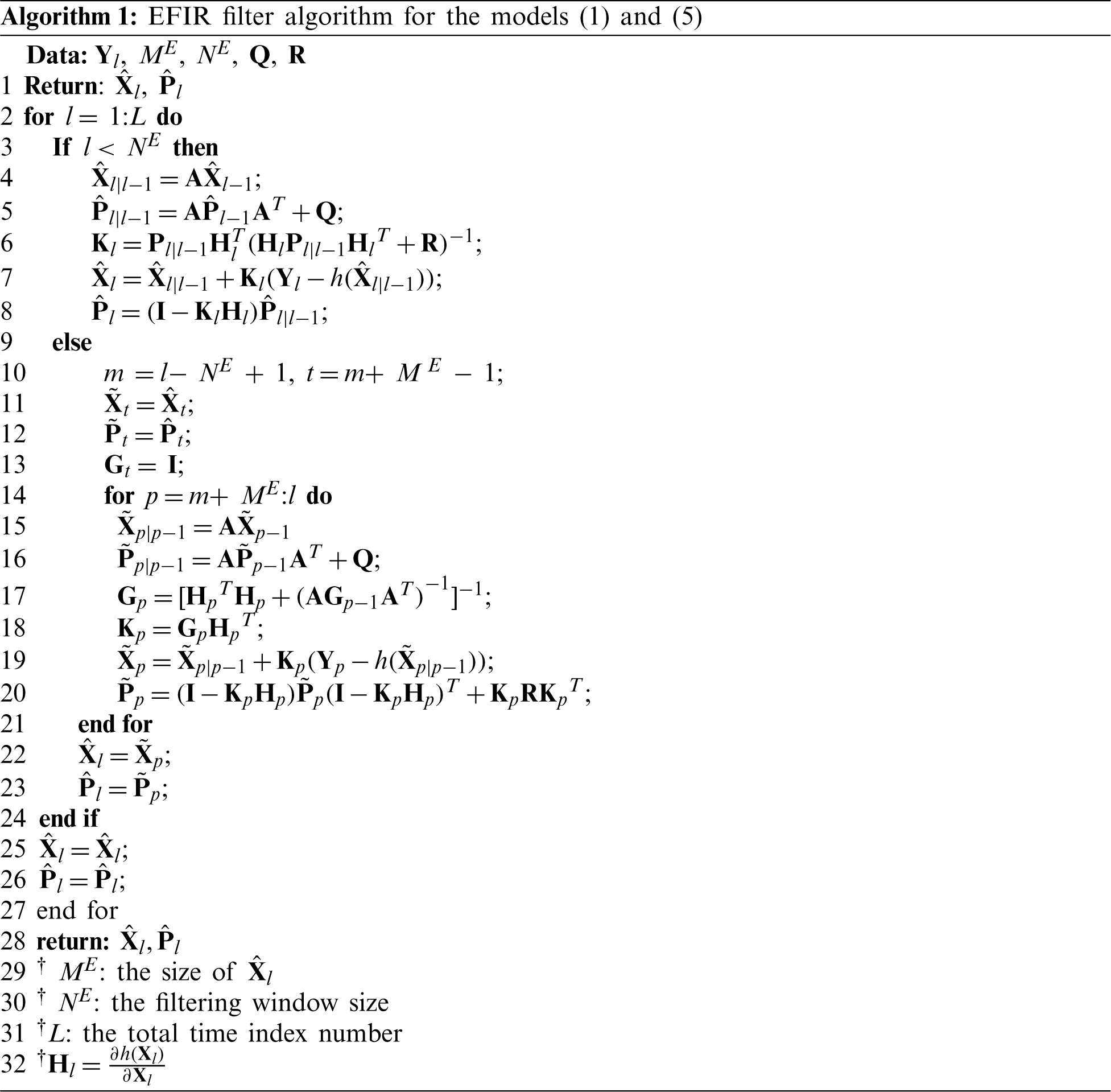
When the forward EFIR filter works, the
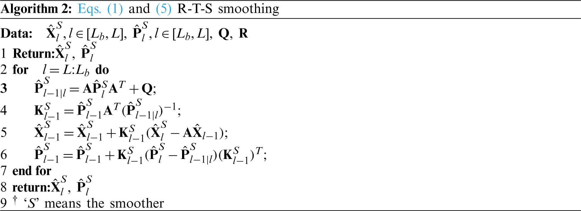
In the R-T-S smoothing algorithm, we set the
where superscript ‘S’ means the smoother. The smoothing gain Kl can be computed as the Eq. (7).
Then, Eqs. (8) and (9) calculate
3.3 Multi-Interval Smoothing Scheme
From the Algorithm 2, it can be seen easily that the R-T-S smoothing using the
• To the east and the north position (xl, yl), we firstly set one threshold door for the position change rate in the east direction (Δ xl = xl − xl − 1) and north (Δ yl = yl − yl − 1) direction.
• When the Δ xl ≤ door, the east position of the robot is considered as the stance, and we set Lx = l. If it is the first time that
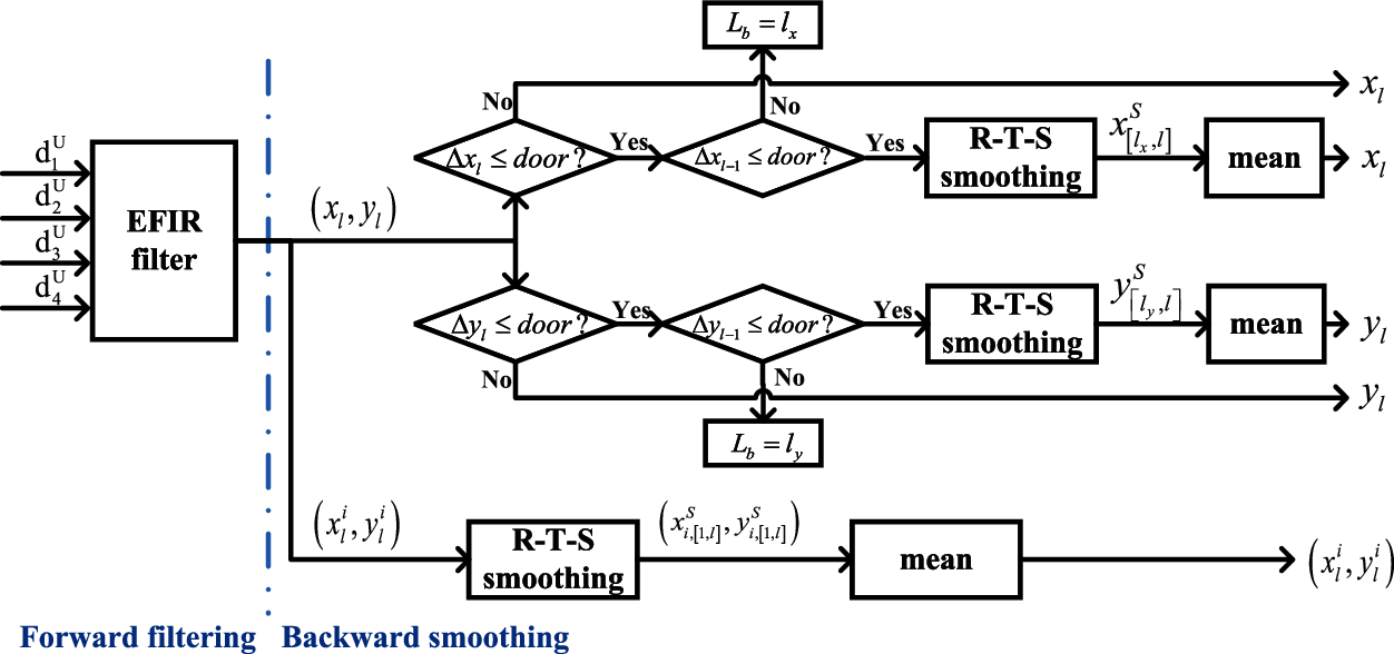
Figure 2: Multi-interval R-T-S smoothing algorithm structure
• When the Δ yl ≤ door, similar to the previous step, the robot's north position is considered as the stance, we set Ly = l. If it is the first time that Δy l − 1 > door change to Δ yl ≤ door, we set Lby = l. The R-T-S smoothing algorithm will be work for smoothing the EFIR filter outputs
• To the UWB RN's position
The multi-interval EFIR R-T-S smoothing for the Eqs. (1) and (5) can be listed in Algorithm 3.
The following part describes experiments for performance verification of the method using real-world data. First, the experiment configurations are introduced. Second, the results are investigated and performance is analyzed.
In this subsection, the experiment configurations are introduced. The real test is done inside the 7th building of University of Jinan, which can be seen in Fig. 3. This work employs the UWB localization system, mobile robot, and the computer to test. The UWB localization system employs the DW−1000 based localization system, which includes one UWB BN (fixed on the mobile robot) and four UWB RNs (fixed on the selected positions so that the positions of RNs are stance), The BN can measure the ranges
where ‘+’ and ‘-’ mean the errors of the UWB RN's position. For example, ‘7.21 + 0.15’ means the the errors of the UWB RN's position is 0.15 m.
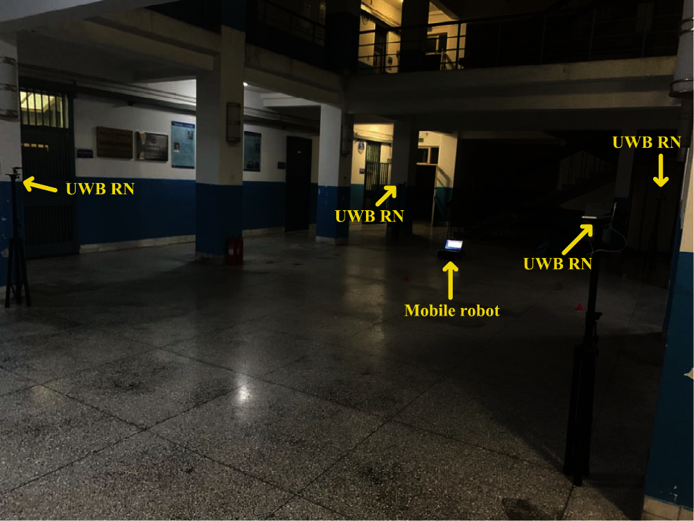
Figure 3: The test environment in the 7th building
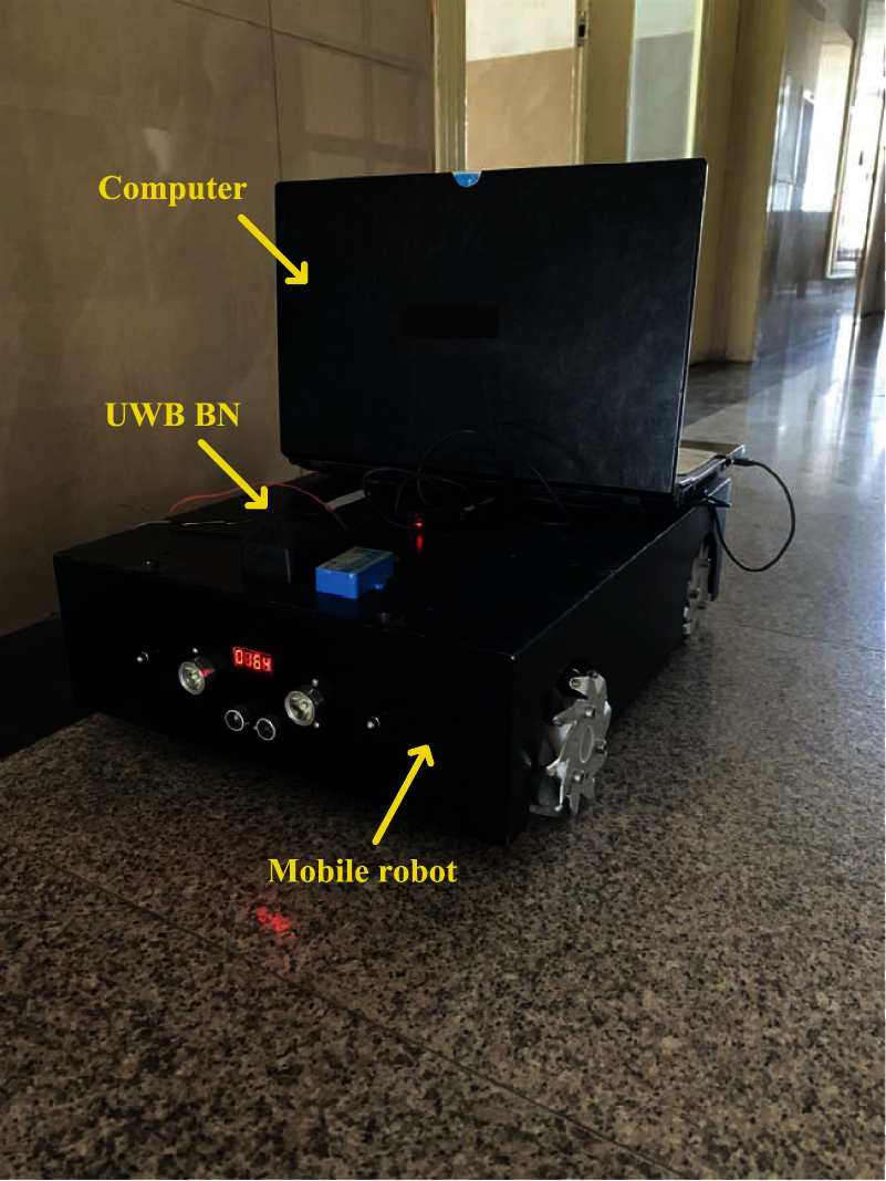
Figure 4: The mobile robot with the UWB BN
From the models (1) and (5) (through EFIR filter), we can get that the ME = 12. And the optimal NE can be found by the follows:
where
The effect of NEN on the localization error using a set of independent data with 200 sampling points is sketched in Fig. 5. From the figure, one can see that the
4.2 The Performance of the Multi-Interval ERTS Smoother for the Trajectory Estimation
In this section, the performances of the UWB, EFIR, and the multi-interval ERTS smoother will be investigated. Fig. 6 shows the trajectories measured by the UWB, EFIR, and the multi-interval ERTS smoother. Fig. 7 shows errors in the east and north position and as we can see, both the EFIR filter and the multi-interval ERTS smoother can reduce the localization errors when being compared to the UWB. Also, the proposed multi-interval ERTS smoother's path is much closer to the ground truth path. Table 1 shows the root mean square errors (RMSEs) given by UWB, EFIR, and multi-interval ERTS smoother. We can see that the proposed multi-interval ERTS smoother has the lowest position error. East- and north-direction positioning errors of the multi-interval ERTS smoother are 0.1175 and 0.0932 m, which improved by 25.36% and 36.92% respectively compared with the EFIR filter. It should be pointed out that the EFIR filter is unsuitable for the estimation of the north position due to the uncertain beacons. Fig. 8 shows the displacements in directions east (Δ xl) and north (Δ yl). Fig. 8 also shows the east- and north-directioned judgment for stance.
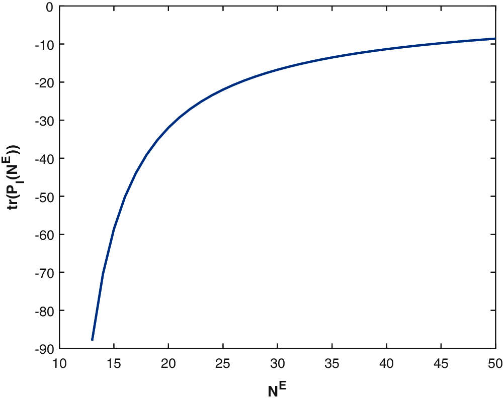
Figure 5: The effect of NEN on the localization error
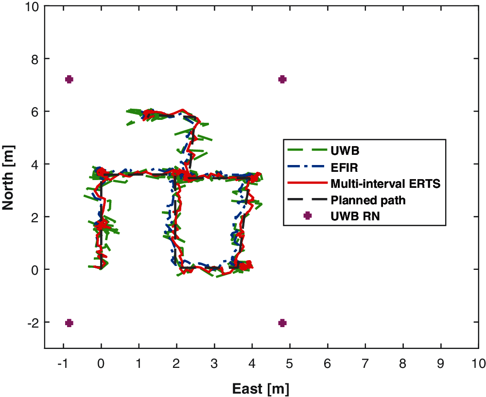
Figure 6: The trajectories measured by the UWB, EFIR, multi-interval ERTS smoother, and the planned path
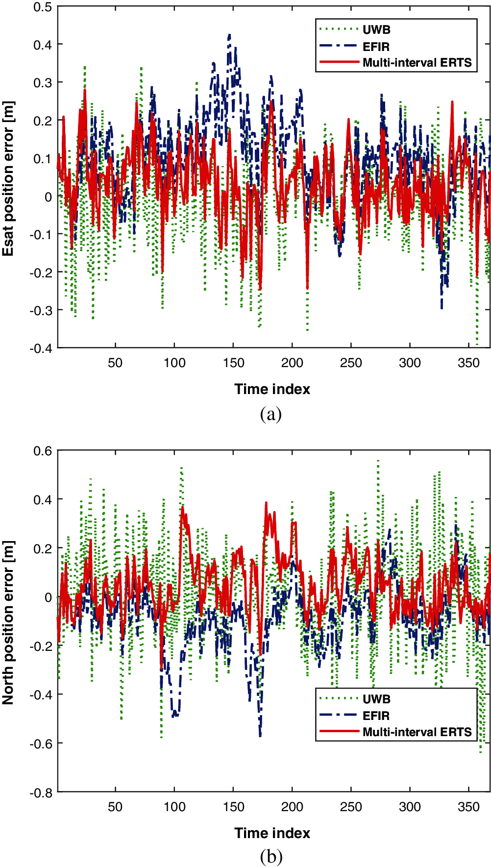
Figure 7: The localization error. Directions: (a) East (b) North
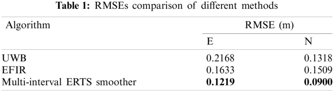
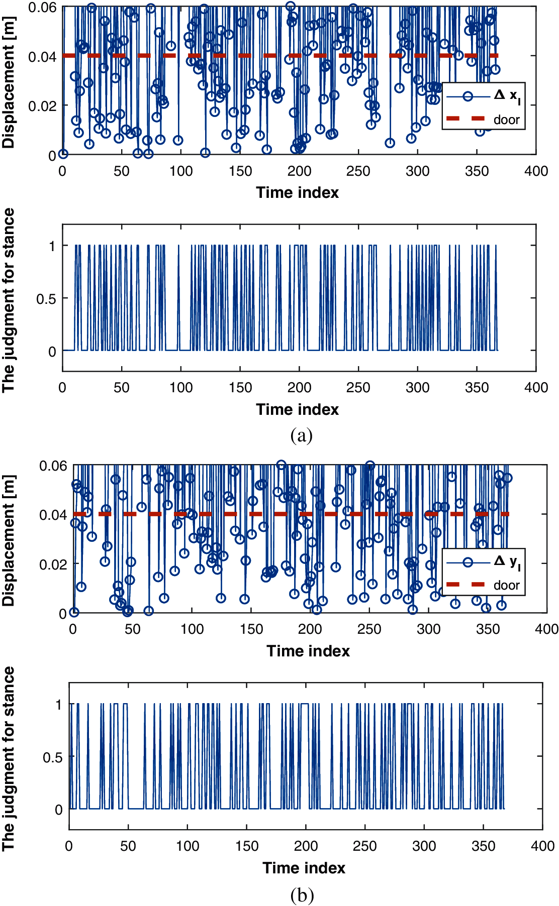
Figure 8: The localization error. Directions: (a) East (b) North
4.3 The Performance of the Multi-Interval ERTS Smoother for the Estimation of the UWB RNs’ Position
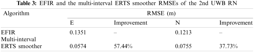
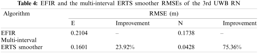
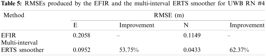
In this section, the performances of the EFIR and the multi-interval ERTS smoother for the estimation of the UWB RNs’ position will be investigated. Fig. 9 shows the estimation of the UWB RNs’ position using the EFIR and the multi-interval ERTS smoother. The RMSEs produced by the EFIR and the multi-interval ERTS smoother for UWB RN #1, #2, #3, and #4 are sketched in the Tables 2–5. From the figure and the tables, we can see obviously that the multi-interval ERTS smoother is effectively to estimate the UWB RN's position. Compared with the EFIR filter, the proposed multi-interval ERTS smoother improved by the 83.51%, 81.61%, 57.44%, 37.73%, 23.92%, 75.36%, 53.75%, and 62.37%.
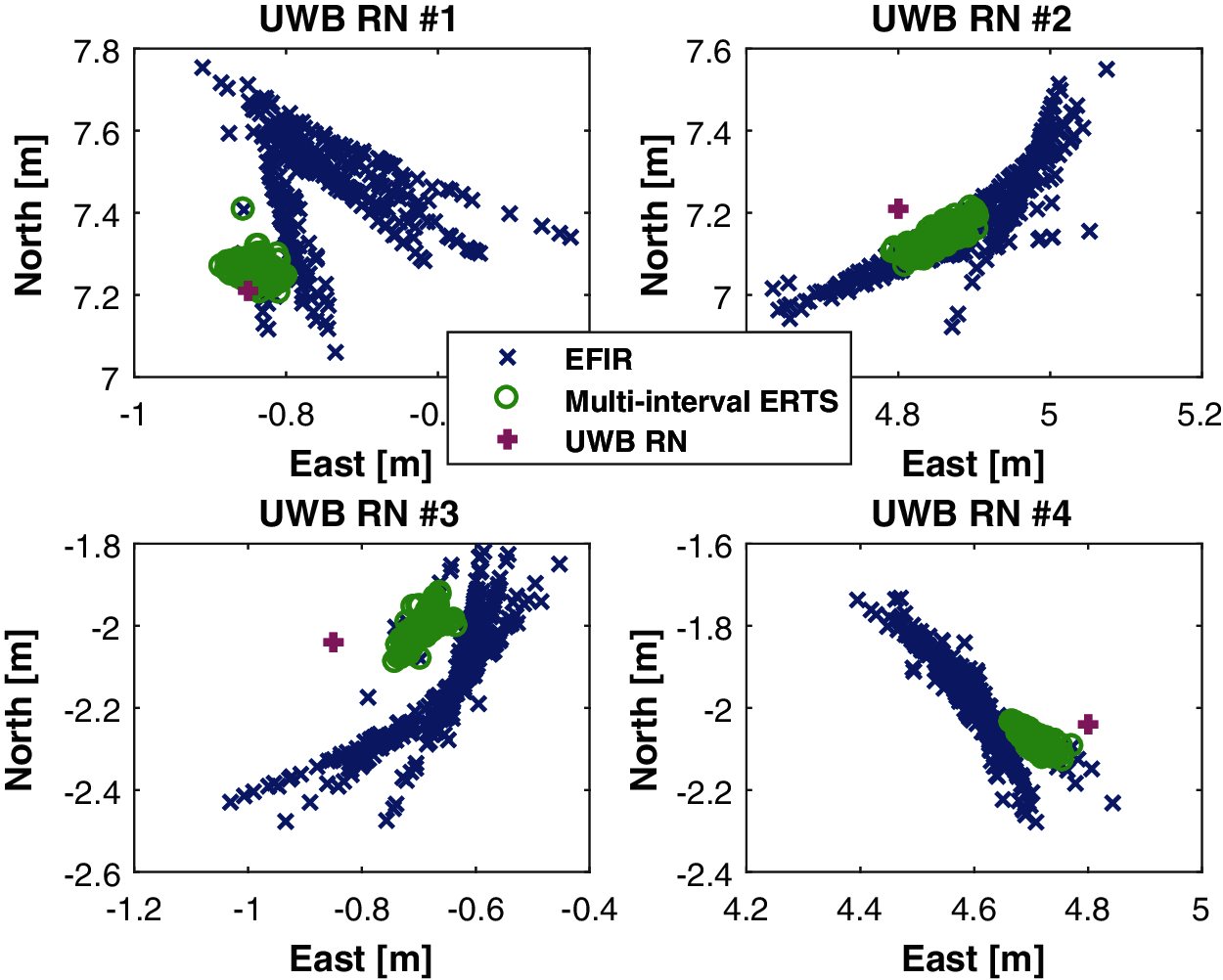
Figure 9: The estimation of the UWB RN’s position using the FIR and multi-interval ERTS smoother

Range-only UWB SLAM for robot localization employing multi-interval EFIR R-T-S smoother has been proposed in this work. The contribution of this work resides in the following:
• An indoor robot's localization scheme is designed for fusing the range-only UWB measurement.
• A new EFIR R-T-S smoothing algorithm using the EFIR filter and the R-T-S smoothing for forward filtering and the backward smoothing method is designed.
• A new smoothing scheme is proposed for the estimation of the east position, north position, and the UWB RN's position, respectively.
• An experiment using real-world data is conducted and verifies that the proposed multi-interval EFIR R-T-S smoothing algorithm improves the performance.
Funding Statement: The authors received no specific funding for this study.
Conflicts of Interest: The authors declare that they have no conflicts of interest to report regarding the present study.
1. Xu, Y., Shmaliy, Y. S., Ma, W., Jiang, X., Guo, H. (2021). Improving tightly LiDAR/Compass/Encoder-integrated mobile robot localization with uncertain sampling period utilizing EFIR filter. Mobile Networks and Applications, 26(5), 1–9. DOI 10.1007/s11036-020-01680-7. [Google Scholar] [CrossRef]
2. Rafflin, C., Fournier, A. (1996). Learning with a friendly interactive robot for service tasks in hospital environments. Autonomous Robots, 3(4), 399–414. DOI 10.1007/BF00240652. [Google Scholar] [CrossRef]
3. Zhuang, Y., Hua, L., Wang, Q., Cao, Y., Thompson, J. S. (2019). Visible light positioning and navigation using noise measurement and mitigation. IEEE Transactions on Vehicular Technology, 68(11), 11094–11106. DOI 10.1109/TVT.25. [Google Scholar] [CrossRef]
4. Xu, Y., Shmaliy, Y. S., Ahn, C. K., Shen, T., Zhuang, Y. (2021). Tightly-coupled integration of INS and UWB using fixed-lag extended UFIR smoothing for quadrotor localization. IEEE Internet of Things Journal, 8(3), 1716–1727. DOI 10.1109/JIoT.6488907. [Google Scholar] [CrossRef]
5. El-Sheimy, N., Li, Y. (2021). Indoor navigation: State of the art and future trends. Satellite Navigation, (2), 7. DOI 10.1186/s43020-021-00041-3. [Google Scholar] [CrossRef]
6. Shi, T., Zhuang, X., Xie, L. (2021). Performance evaluation of multi-GNSSs navigation in super synchronous transfer orbit and geostationary earth orbit. Satellite Navigation, 2(1), 5. DOI 10.1186/s43020-021-00036-0. [Google Scholar] [CrossRef]
7. Rodina, J. (2013). Localization of small mobile robot by low-cost GPS receiver. Journal of Mechanics Engineering and Automation, (8), 522–528. [Google Scholar]
8. Liu, R., Zhang, J., Chen, S., Yang, T., Arth, C. (2021). Accurate real-time visual SLAM combining building models and GPS for mobile robot. Journal of Real-Time Image Processing, 18, 419–429. DOI 10.1007/s11554-020-00989-6. [Google Scholar] [CrossRef]
9. Liu, P., Qin, H., Cong, L. (2019). The unified form of code biases and positioning performance analysis in global positioning system (GPS)/BeiDou navigation satellite system (BDS) precise point positioning using real triple-frequency data. Sensors, 19(11), 1–17. DOI 10.3390/s19112469. [Google Scholar] [CrossRef]
10. Choi, B. S., Lee, J. W., Lee, J. J., Park, K. T. (2011). A hierarchical algorithm for indoor mobile robot localization using RFID sensor fusion. IEEE Transactions on Industrial Electronics, 58(6), 2226–2235. DOI 10.1109/TIE.2011.2109330. [Google Scholar] [CrossRef]
11. Al-Jarrah, M. A., Al-Dweik, A., Alsusa, E., Damiani, E. (2019). RFID reader localization using hard decisions with error concealment. IEEE Sensors Journal, 19(17), 7534–7542. DOI 10.1109/JSEN.7361. [Google Scholar] [CrossRef]
12. He, J., Liu, R., Xiao, Y., Liang, G., Fu, Y. (2018). Moving object localization by fusing RFID phase difference and laser scanning. Chinese Journal of Scientific Instrument, 39(2), 81–88. DOI 10.19650/j.cnki.cjsi.j1702720. [Google Scholar] [CrossRef]
13. Luo, R. C., Chuang, C. T., Huang, S. S. (2007). RFID-based indoor antenna localization system using passive tag and variable RF-attenuation. Conference of the IEEE Industrial Electronics Society, 2254–2259. DOI 10.1109/IECON.2007.4460379. [Google Scholar] [CrossRef]
14. Canedo-Rodriguez, A., Rodriguez, J. M., Alvarez-Santos, V., Iglesias, R., Regueiro, C. V. (2015). Mobile robot positioning with 433-MHz wireless motes with varying transmission powers and a particle filter. Sensors, 15(5), 10194–10220. DOI 10.3390/s150510194. [Google Scholar] [CrossRef]
15. Decarli, N., Guidi, F., Dardari, D. (2016). Passive UWB RFID for tag localization: Architectures and design. IEEE Sensors Journal, 16(5), 1385–1397. DOI 10.1109/JSEN.2015.2497373. [Google Scholar] [CrossRef]
16. Xu, Y., Shmaliy, Y. S., Li, Y., Chen, X. (2017). UWB-Based indoor human localization with time-delayed data using EFIR filtering. IEEE Access, 5, 16676–16683. DOI 10.1109/ACCESS.2017.2743213. [Google Scholar] [CrossRef]
17. Xu, Y., Shmaliy, Y. S., Ki, A. C., Tian, G., Chen, X. (2018). Robust and accurate UWB-based indoor robot localisation using integrated EKF/EFIR filtering. IET Radar, Sonar and Navigation, 1(7), 750–756. DOI 10.1049/iet-rsn.2017.0461. [Google Scholar] [CrossRef]
18. Zhao, S., Huang, B. (2020). Trial-and-error or avoiding a guess? Initialization of the Kalman filter. Automatica, 121, 109184. DOI 10.1016/j.automatica.2020.109184. [Google Scholar] [CrossRef]
19. Tesli, L., Krjanc, I., Klan Ar, G. (2010). Using a LRF sensor in the kalman-filtering-based localization of a mobile robot. ISA Transactions, 49(1), 145–153. DOI 10.1016/j.isatra.2009.09.009. [Google Scholar] [CrossRef]
20. Benini, A., Mancini, A., Longhi, S. (2013). An IMU/UWB/Vision-based extended kalman filter for mini-UAV localization in indoor environment using 802.15.4a wireless sensor network. Journal of Intelligent and Robotic Systems, 70(1−4), 461–476. DOI 10.1007/s10846-012-9742-1. [Google Scholar] [CrossRef]
21. Cui, B., Chen, X., Xinhua, T. (2017). Improved cubature Kalman filter for GNSS/INS based on transformation of posterior sigma-points error. IEEE Transactions on Signal Processing, 65(11), 2975–2987. DOI 10.1109/TSP.2017.2679685. [Google Scholar] [CrossRef]
22. Hu, G., Gao, B., Zhong, Y., Gu, C. (2020). Unscented Kalman filter with process noise covariance estimation for vehicular INS/GPS integration system. Information Fusion, 64, 194–204. DOI 10.1016/j.inffus.2020.08.005. [Google Scholar] [CrossRef]
23. Cui, B., Wei, X., Chen, X., Li, J., Li, L. (2019). On sigma-point update of cubature Kalman filter for GNSS/INS under GNSS-challenged environment. IEEE Transactions on Vehicular Technology, 68(9), 8671–8682. DOI 10.1109/TVT.25. [Google Scholar] [CrossRef]
24. Zhao, S., Shmaliy, Y. S., Liu, F. (2016). Fast Kalman-like optimal unbiased FIR filtering with applications. IEEE Transactions on Signal Processing, 64(9), 2284–2297. DOI 10.1109/TSP.2016.2516960. [Google Scholar] [CrossRef]
25. Zhao, S., Shmaliy, Y. S., Ahn, C. K., Liu, F. (2018). Adaptive-horizon iterative UFIR filtering algorithm with applications. IEEE Transactions on Industrial Electronics, 65(8), 6393–6402. DOI 10.1109/TIE.41. [Google Scholar] [CrossRef]
26. Pomarico-Franquiz, J. J., Shmaliy, Y. S. (2014). Accurate self-localization in RFID tag information grids using FIR filtering. IEEE Transactions on Industrial Informatics, 10(2), 1317–1326. DOI 10.1109/TII.2014.2310952. [Google Scholar] [CrossRef]
27. Zhuang, Y., Wang, Q., Shi, M., Cao, P., Qi, L. et al. (2019). Low-power centimeter-level localization for indoor mobile robots based on ensemble Kalman smoother using received signal strength. IEEE Internet of Things Journal, 6(4), 6513–6522. DOI 10.1109/JIoT.6488907. [Google Scholar] [CrossRef]
 | This work is licensed under a Creative Commons Attribution 4.0 International License, which permits unrestricted use, distribution, and reproduction in any medium, provided the original work is properly cited. |