| Computer Modeling in Engineering & Sciences |
DOI: 10.32604/cmes.2022.017368
ARTICLE
Design of Multi-Coupled Laminates with Extension-Twisting Coupling for Application in Adaptive Structures
1College of Aerospace Science and Engineering, National University of Defense Technology, Changsha, 410073, China
2Hunan Key Laboratory of Intelligent Planning and Simulation for Aerospace Missions, Changsha, 410073, China
*Corresponding Author: Daokui Li. Email: lidaokui@nudt.edu.cn
Received: 07 May 2021; Accepted: 16 July 2021
Abstract: The multiple coupling of composite laminates has a unique advantage in improving the macro mechanical properties of composite structures. A total of three hygro-thermally stable multi-coupled laminates with extension-twisting coupling were presented, which were conducive to the formation of passive adaptive structures. Then, the multi-coupled laminates were used to design the bending-twisting coupled box structure, in which the configuration of laminate and box structure could be extended to variable cross-section configuration. The optimal design of stacking sequence was realized, the optimization objectives of which were to maximize bending-twisting coupling of box structure and extension-twisting coupling of laminate, respectively. The effects of multiple coupling on hygro-thermal stability, coupling, failure strength, buckling load, robustness and other comprehensive mechanical properties of laminates and box structures were analyzed by parametric modeling method. The results show that the extension-twisting coupling of laminate and the bending-twisting coupling of box structures can be greatly improved by 450% and 260% at maximum, respectively. Meanwhile, it would have a negative impact on the failure strength and buckling load, which, however, can be minimized by a reasonable paving method. Multi-coupled laminates have good robustness, and the bending-twisting coupling helps improve robustness. Finally, the hygro-thermal stability and mechanical properties were verified by numerical simulation with finite element method.
Keywords: Multi-coupled laminate; passive adaptive structures; optimal design; mechanical properties; numerical simulation
Passive adaptive structure has become the forefront and research hotspot in the present era with its unique advantages in the field of aerospace and wind power. For instance, the bending-twisting coupled principle bearing structure can control the aeroelastic deformation of the forward-swept wing aircraft, thereby inhibiting the rapid decline of the critical velocity caused by aeroelastic divergence and improving design performance and aeroelastic properties [1,2]. The adaptive bending-twisting coupled wind turbine blades structure enables the blades to change their aerodynamic torsion angles in real time according to wind speed, thus effectively avoiding blade damage and fracture under the action of strong wind [3,4].
The stiffness characteristics of the passive adaptive structure can be realized by the paving design of composite laminate [5]. The reasonable paving angle of each lamina enables the laminates to have special couplings, including extension-shearing [6], extension-twisting [7] and bending-twisting couplings [8], etc. Then, the structures composed of these laminates demonstrate the required coupling stiffness. It is worth noting that hygro-thermal deformation should be firstly considered in the paving design process of laminates. Under this premise, many scholars have studied various types of laminates to varying degrees. On the basis of the concept of hygro-thermal warpage stability proposed by Winckler [9], Cross et al. [10] designed asymmetrical composite materials without hygro-thermal warpage deformation. Then, Haynes et al. [7] optimized the stacking sequence of hygro-thermally warpage stable composite materials with extension-twisting coupling and bending-twisting coupling [11]. Subsequently, York successively studied the hygro-thermally warpage stable laminates of standard laminates [6] and other special angle laminates [12], and then designed extension-shearing and bending-twisting coupled laminated plates [13] to maximize the shear buckling strength of the adaptive flexible wing box structure. On this basis, a large number of researches on laminate layup design have been carried out [14,15]. Furthermore, the buckling load and coupling of hygro-thermally stable laminates were simultaneously considered by Li in the process of optimization design, including extension-shearing coupled laminates [16] and extension-twisting coupled laminates [17]. Cui designed and optimized the single fiber [18] and interlayer hybrid [19] extension-shearing coupled laminates with hygro-thermal stability.
The above-mentioned research is mainly aimed at the single coupling of laminate, and strives to achieve the best mechanical properties of laminates or composite structures formed by laminates. The single coupling of laminate limits the range of the paving angle to a large extent despite the fact that it is easy to design, resulting in the inability of the laminate to effectively give play to its advantages in improving mechanical properties in the form of free layup. Moreover, the single coupling of laminate is likely to cause limitations, such as bending-twisting coupling that may reduce buckling load [20]. Therefore, this article focuses on multi-coupled laminates, expecting to achieve a significant improvement in the mechanical properties.
The multi-coupled laminates refer to laminates that contain two or more couplings that can exist independently at the same time. There are few studies on multi-coupled laminates in existing research. Moore et~al. [5] realized the paving design of the hygro-thermally isotropic laminate with the maximum extension-twisting coupling, and the optimized laminate had both extension-twisting coupling and extension-bending couplings. Subsequently, York et al. [13] designed a laminate with both extension-shearing and bending-twisting couplings to maximize the shear buckling strength of the adaptive flexible wing box structure. In view of the advantages of single-coupled laminates in improving mechanical properties and overcoming the limitations, the paving design of multi-coupled laminates was studied.
The innovation of this article lies in improving the comprehensive mechanical properties of the composite structure from the perspective of the multi-couplings of the laminate. The universal analytical conditions for hygro-thermally stable multi-coupled laminates with extension-twisting coupling were established. Then, the multi-coupled laminates were used to design hygro-thermally stable adaptive structures, in which the configuration of laminate and structure could be extended to variable cross-section configuration. The optimal design was realized for the multi-coupled laminates and adaptive structures. Meanwhile, the effect of multi-coupling on laminates and adaptive structures was explored in terms of coupling effect, failure strength, bucking load and robustness.
There are many kinds of multi-coupled laminates. Considering the extension-twisting coupling (a kind of extensively studied coupling) of laminate plays a notable role in the design of adaptive structures, the multi-coupled laminates with such coupling are studied in the following research. In order to maximize the advantages of laminates, the paving form of laminates should be no longer limited to special forms such as standard layups and symmetrical layups. The possible coupling, except extension-twisting coupling, may possess include one or more of the following couplings: extension-shearing, extension-bending, bending-twisting and shearing-twisting couplings. It is worth noting that the coexistence of extension-shearing coupling and extension-twisting coupling will not be conducive to the improvement of the adaptive ability of the structure. It mainly reflects that the paving orders of the upper and lower flanges of adaptive box structure are completely the opposite. Thus, other couplings here do not include extension-shearing coupling.
In addition to extension-twisting coupling, other coupling of double-coupled laminates may include one of the following couplings: extension-bending coupling, shearing-twisting coupling and bending-twisting coupling. The ASBltDS laminate (extension-bending and extension-twisting coupled) was firstly studied. Based on the classical laminates theory (CLT) [21], extension-twisting coupling coefficients
The stiffness coefficients
where, the expressions of
where, H is the thickness of the laminate;
The relationships of hygro-thermal stability for laminates are [18]
However,
Then, considering ASBtDF laminate (bending-twisting and extension-twisting coupled), whose stiffness equation is
Inserting Eq. (2) into Eq. (6), it yields
Substituting Eq. (7) into Eq. (5), we obtain hygro-thermally stable ASBtDF laminate
Furthermore, the extension-bending coupling must co-exist with shearing-twisting coupling (
2.2 Triple- and Quadruple-Coupled Laminates
The shearing-twisting coupling will produce the extension-bending coupling (
The stiffness equation of ASBFDS laminate is
Substituting Eq. (2) into Eq. (9), it gives
Substituting Eq. (10) into Eq. (5), we obtain the hygro-thermally stable ASBFDS laminate, namely
Furthermore, the stiffness equation of ASBltDF laminate is expressed as
Substituting Eq. (2) into Eq. (12), it gives
However,
Similarly, for composite ASBFDF laminates, the stiffness equation is
Substituting Eq. (2) into Eq. (14), it yields
Substituting Eq. (15) into Eq. (5), we obtain hygro-thermally stable ASBFDF laminate, namely
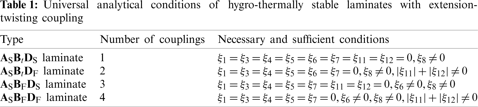
In brief, when the extension-twisting coupled laminates with three or more couplings are used to construct hygro-thermally stable composite structures, only ASBFDS laminate (triple-coupled) and ASBFDF laminate (quadruple-coupled) are presented, as shown in Table 1. As can be seen from the table, ASBtDS laminate is the single coupled laminate with extension-twisting coupling and shearing-bending coupling. Since these two couplings cannot exist separately, ASBtDS laminate is recorded as the single-coupled laminate. The necessary and sufficient conditions of the hygro-thermally stable ASBtDS laminate are given in [22].
3 Bending-Twisting Coupled Structures
There are two types of typical composite adaptive structures, namely bending-twisting coupled structure and extension-twisting coupled structure [23]. Both of these adaptive structures can be designed by laminates with extension-twisting coupling. The method of studying the extension-twisting coupled adaptive structure is similar to that of the bending-twisting coupled adaptive structure, so this article only focuses on only one adaptive structure. The bending-twisting coupled structure, which has broad application prospects in the field of aerospace and wind power, is studied here.
The geometric shape of bending-twisting coupled variable cross-section box structure is shown in Fig. 1, where the bending-twisting coupled structure is composed of an upper flange, a lower flange and two web laminates. Meanwhile, the size of laminate can be not limited to rectangular shape. The cross-sectional area from the fixed end to the free end gradually decreases. The reference frame indicates the frame of box structure with equal section, which is to help describe the size of the variable cross-section box structure. The angles between the upper and lower flanges with the vertical surfaces of the fixed end (surface C1C2C3C4 and surface C5C6C7C8) are
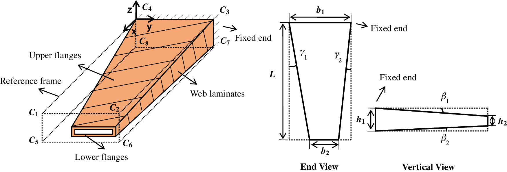
Figure 1: Geometric diagram of bending-twisting coupled variable cross-section box structure
Considering the outstanding performance of extension-twisting coupling of laminate on constituting the bending-twisting coupling of box structure, the laminates with extension-twisting coupling in Table 1 are taken to design the variable cross-section bending-twisting coupled box structure, hoping to maximize torsion deformation under the same bending moment. Thus, the optimization goal is to maximize the bending-twisting coupling of the box structure. Furthermore, merits and demerits of multi-couplings in the application of adaptive structures should be explored. The extension-twisting coupling of multi-coupled laminate mainly determines the bending-twisting coupling of box structure, so the optimization goal should also be to maximize extension-twisting coupling, which can be achieved by the extension-twisting coupled flexibility coefficient
The torsion deformation of the box structure can be measured by the vertical (z-direction) displacement difference c of the two corner points of the free end of upper or lower flanges, as shown in Fig. 2. The design of the bending-twisting coupled structure with multi-coupling laminate makes the coupling performance of the structure more complicated, which leads to the difficulty in the analytical expression of the static deformation of the structure. Therefore, the parametric modeling method is used to achieve high-precision solution of the displacement of each point of bending-twisting coupled structure with variable size and stacking sequence, and the corresponding deformation results can be extracted with the help of the finite element software.
The wing of an executive jet transport (EJT) was used as a research object. In the light of the physical parameters of EJT, the wing size can be set as the lengths of the wing root, wing tip and wingspan are 4.57 m, 1.52 m and 8.26 m, respectively [24]. Considering the complex combination forms of actual wing structure and tiny ratio of skin thickness to wing span, it is pointless to apply the load directly to the skin structure. Therefore, a scaled model of wing structure was taken for the design optimization, with b1 = 100 mm, b2 = 33 mm and L = 180 mm. The height difference between the upper and lower flanges at the fixed end h1 is 10 mm, and the height difference at the free end h2 is 4 mm,
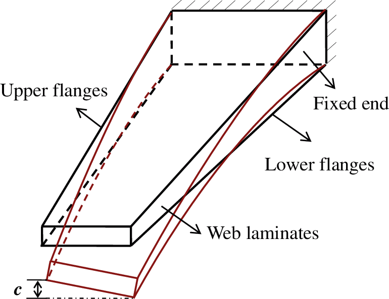
Figure 2: Schematic diagram of torsion deformation of the bending-twisting coupled box structure
The upper and lower flanges of the wing should produce torsion deformation in the same direction. The bending moment of box structure can be equivalent to the force of the same magnitude and opposite direction. Therefore, the paving angle of the upper and lower flanges should be opposite to each other. Compared with the upper and lower flanges, the web laminate is very small in size, and the laminate [60/−60/−60/0/0/0/60/60/0/−60/60/60/−60/−60/−60/0/0/60]T without any couplings is taken. The external bending moment M is 0.12 N⋅m. The constraint conditions are the relationships in Table 1. The optimal mathematical models for four extension-twisting coupled laminates in Table 1 and their bending-twisting coupled box structures are shown in Eqs. (17)–(20), respectively.
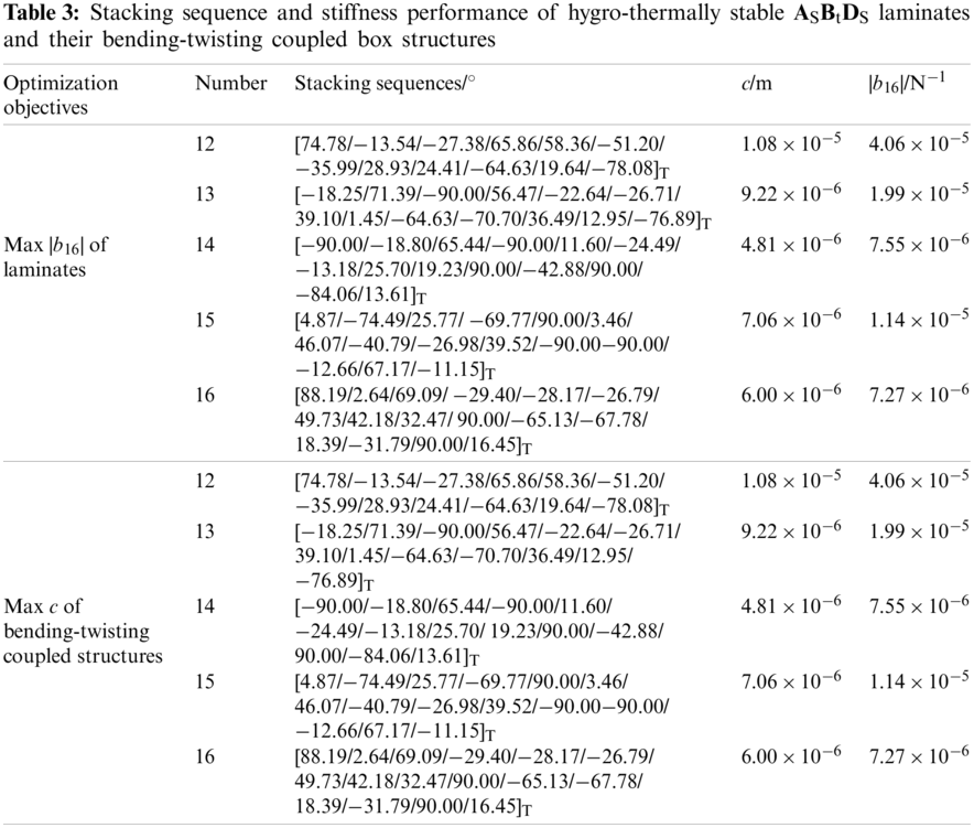
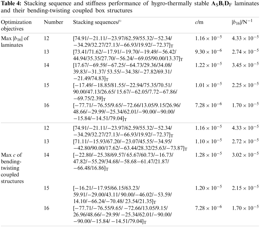
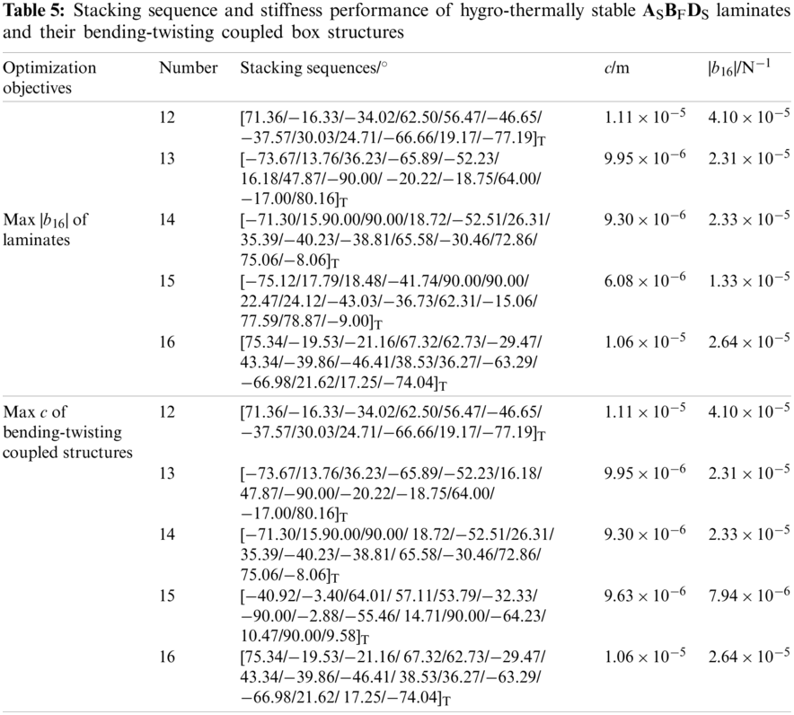
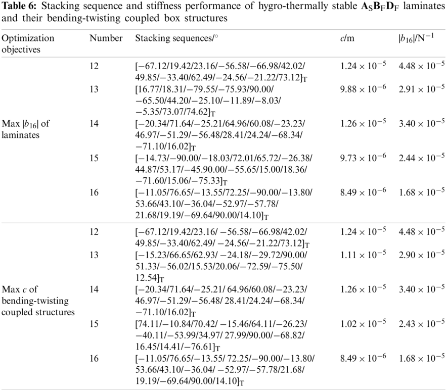
Owing to the strong nonlinear equality constraints, the DE_CMSBHS algorithm was used for optimization combined with the penalty function [18]. The initial population was about 15 times of n (number of plies). The evolutionary algebra was set as 3000 (large enough to ensure convergence). According to the optimized mathematical model shown in Eqs. (17)–(20), the optimal design of laminate and box structure was realized. Tables 3–6 show the stacking sequences, analytical solutions of extension-twisting coupling and torsion deformation of bending-twisting coupled structure, respectively.
Considering that equipment and human errors are often unavoidable when laminates are laid by existing processing technologies, it is meaningful to test the deformation deviation caused by the paving angle deviation for free-layer laminate. Taking the 14-ply laminates with maximum |b16| as examples, the robustness of extension-twisting coupling was verified by using the Monte Carlo method.
Assume that the angle deviation of the k-ply lamina is
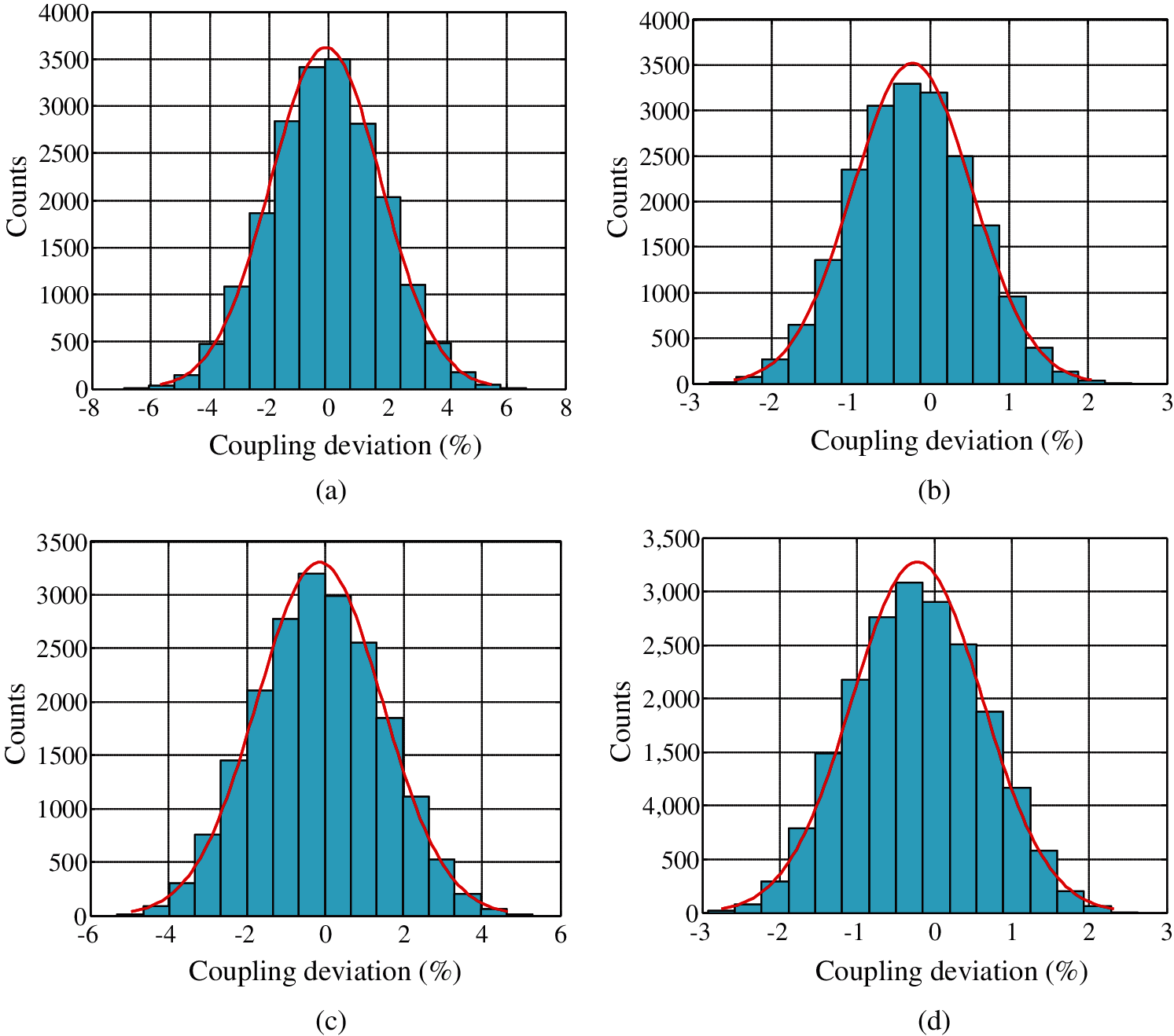
Figure 3: Deviation distribution of extension-twisting coupling of laminates based on 20,000 samples (a) ASBtDS laminate [−3.75%, 3.57%] (b) ASBtDF laminate [−1.70%, 1.28%] (c) ASBFDS laminate [−3.27%, 3.00%] (d) ASBFDF laminate [−1.88%, 1.44%]
The hygro-thermal performance of laminates and box structures was tested by using the FEM, as shown in Tables 3–6. The laminate size was set as a parallel base length of 100 mm and 33 mm, and a height of 180 mm. The size of the box structure was the same as in the optimization process. The boundary condition was a fixed support at the bottom midpoint for laminate and box structure. In addition, the free end of box structure was constrained by the rigid surface RBE2. The laminate was divided into 300 shell elements, and the bending-twisting coupled structure was divided into 840 shell elements in total. The temperature difference was set as 180°C to simulate the curing process.
The free shrinkage deformation results under cooling of laminates and the bending-twisting coupled structure were solved by the software MSC.Nastran, as shown in Fig. 4. In order to analyze the effect of humidity changes on the deformation of laminates, the Abaqus software was used for numerical simulation. The laminate was divided into a total of 2,800 solid elements (Pore Fluid/Stress), and the bending-twisting coupled structure was divided into 27,200 solid elements in total. The relative humidity changed from 50% to 40%. The free contraction displacement cloud of laminates and box structures caused the humidity changes was solved by the “soils” function of the software Abaqus, as shown in Fig. 5. Only the results of 14-ply ASBtDS, ASBtDF, ASBFDS and ASBFDF laminate are presented here, and the results of other laminates are the same. The zero shear strain, bending and twisting curvatures results in both Figs. 4 and 5 illustrate the hygro-thermal stability.
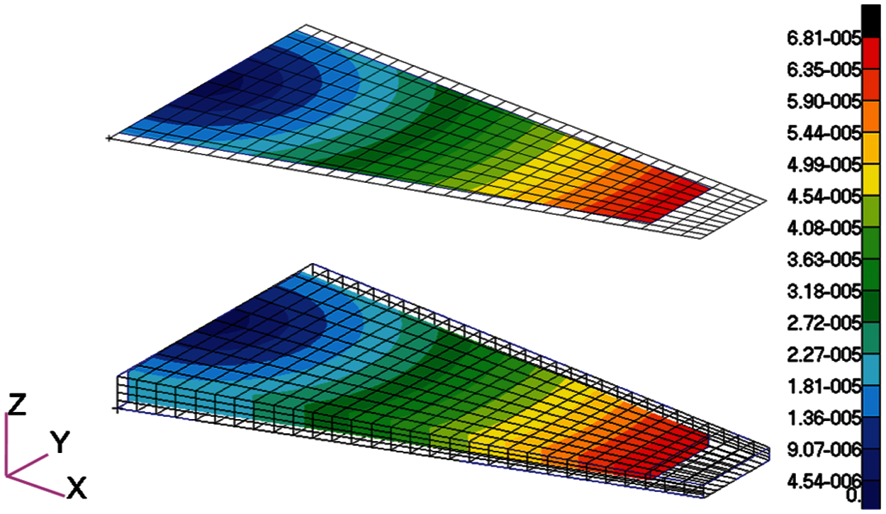
Figure 4: Cooling shrinkage displacement diagrams of 14-ply laminates with maximum extension-twisting coupling in Tables 3–6 (including ASBtDS laminate, ASBtDF laminate, ASBFDS laminate and ASBFDF laminate) and box structures due to the temperature changes, in meters
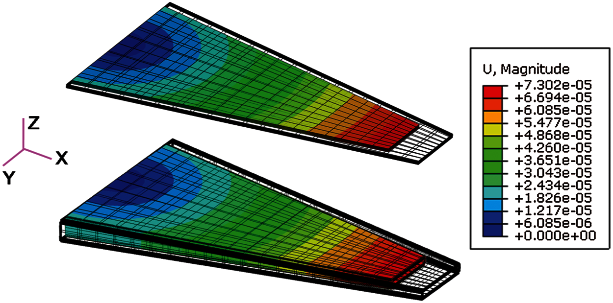
Figure 5: Free contraction displacement diagrams of 14-ply laminates with maximum extension-twisting coupling in Tables 3–6 (including ASBtDS laminate, ASBtDF laminate, ASBFDS laminate and ASBFDF laminate) and box structures due to the humidity changes, in meters
In addition, laminates with different paving angles produce the same thermal linear strains, which suggests that the hygro-thermal linear strain of laminate is independent of the stacking sequence. In view of the fact that the effect of humidity changes on laminates is similar to that of temperature changes, only the thermal coefficient needs to be replaced with the humidity coefficient. Thus, the reasons for this phenomenon were analyzed only from the perspective of temperature changes. The thermal linear strain of the laminate with extension-twisting coupling is expressed as
where the upper corner “T” represents variables related to thermal effects. Since the hygro-effect is similar to the thermal-effect, only the thermal-effect is presented. Then the thermal internal force and thermal moment of the composite laminate can be expressed by two independent parameters: the thermal constant of the material
The material thermal constant
Substituting Eq. (5) into Eq. (22), it gives
Substituting Eq. (24) into Eq. (21), we can further get
Inserting the common analytical conditions
Then Substituting Eq. (25) into Eq. (26), we can further get
From Eq. (27), we can see that
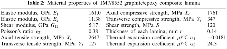
In order to verify the stiffness performance of the laminates, the finite element model of a rectangular laminate with the size of 0.18 by 0.1 m was established. The purpose of using rectangular laminates for verification was to facilitate the extraction of the distortion of laminates. The external load was the axial uniform tension (400 N/m). 800 shell elements were divided and the geometric center of laminate was fixed. The size of the box structure was the same as in the optimal design process, and the bending moment of the free end of the structure M was 0.12 N⋅m. Displacement cloud diagrams of the laminates and the box structures were calculated. The results of 14-ply laminates are shown in Fig. 6 as examples. The results illustrate the deformation of laminate is consistent with the expected design, with the extension-twisting and corresponding couplings. Box-shaped structure produced not only bending deformation but also torsion deformation under the action of bending moment.
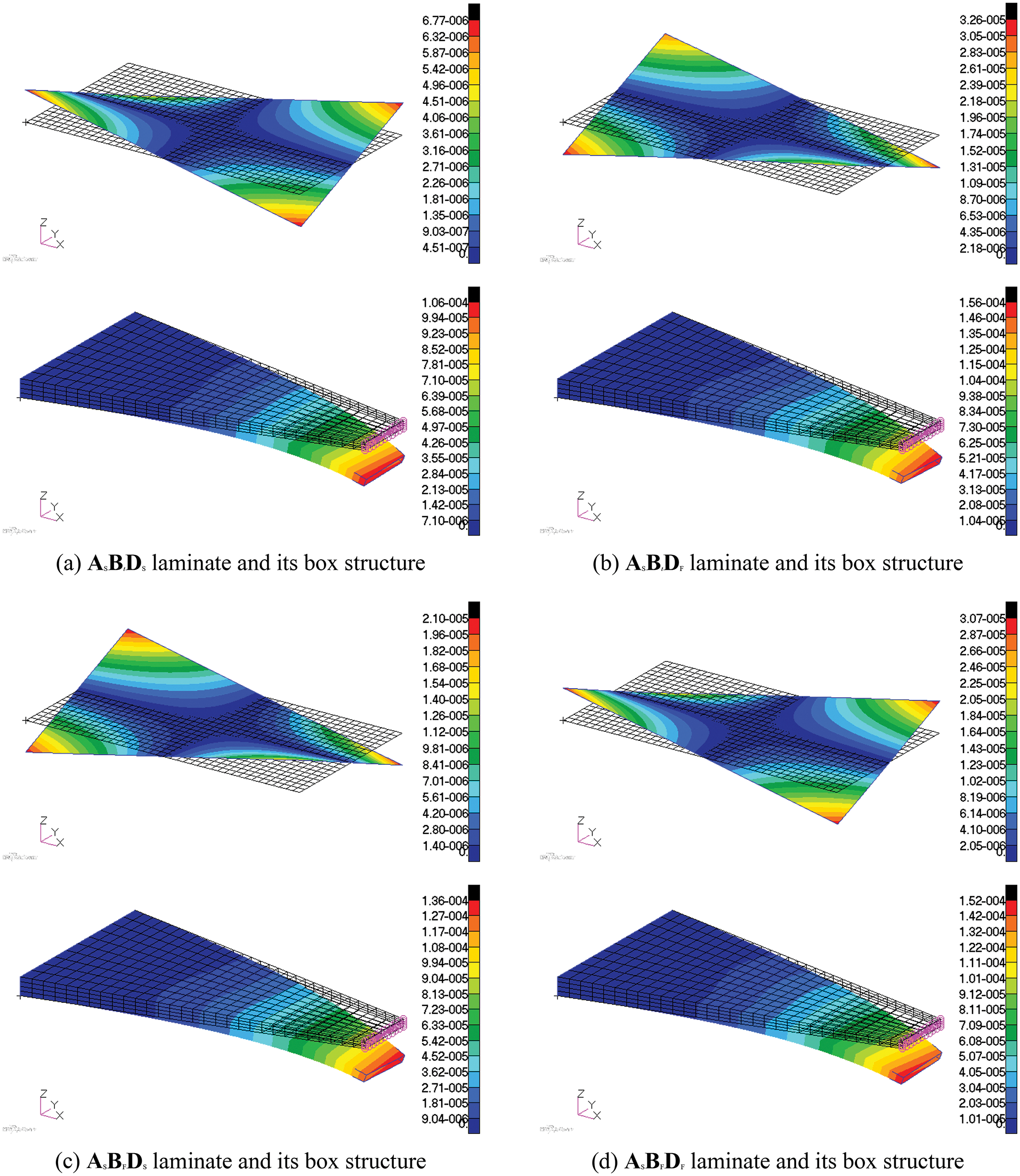
Figure 6: Displacement diagrams of laminates and bending-twisting coupled structures formed by respective laminates, in meters (a) ASBtDS laminate and its box structure (b) ASBtDF laminate and its box structure (c) ASBFDS laminate and its box structure (d) ASBFDF laminate and its box structure
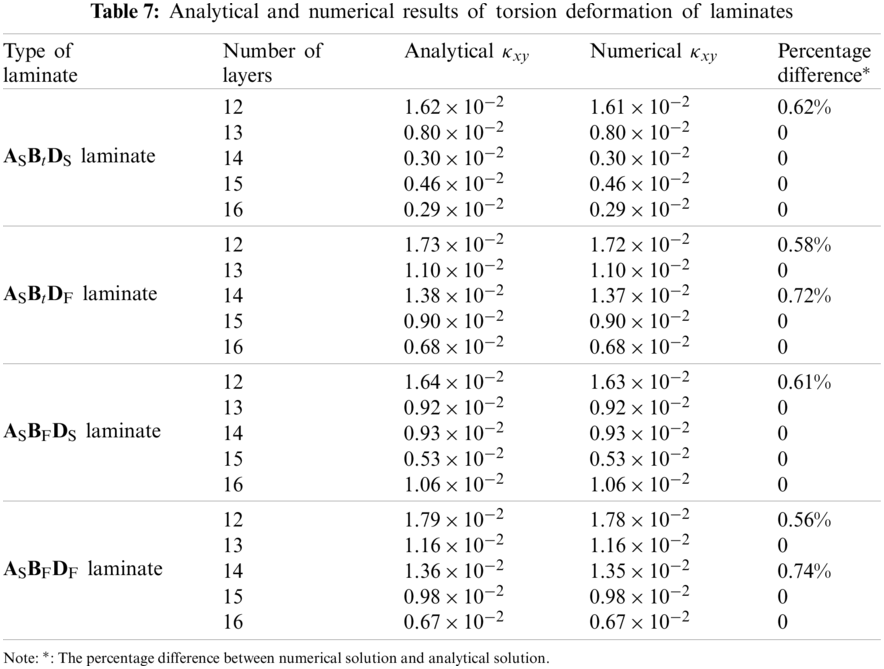
The torsion angle
Table 7 shows the analytical and numerical solutions of torsion deformation of each laminate, as well as the percentage difference and improvement. The results illustrate that the simulation results of torsion deformation of laminate are consistent with the analytical results (difference within 1%), which verifies the accuracy of the extension-twisting coupling.
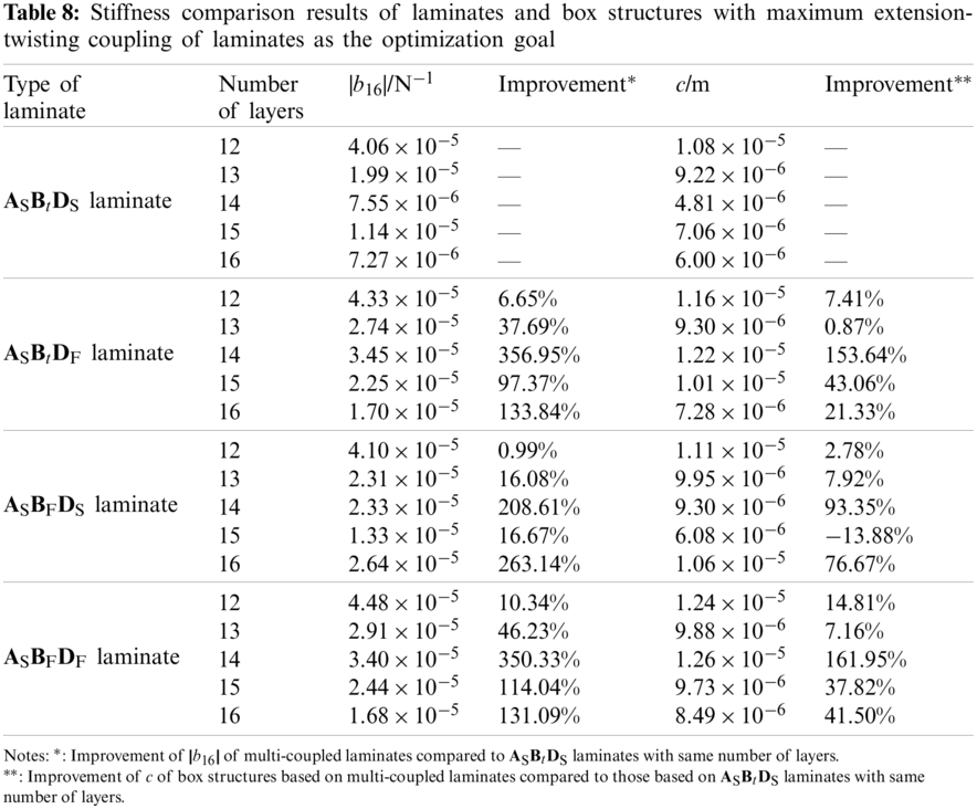
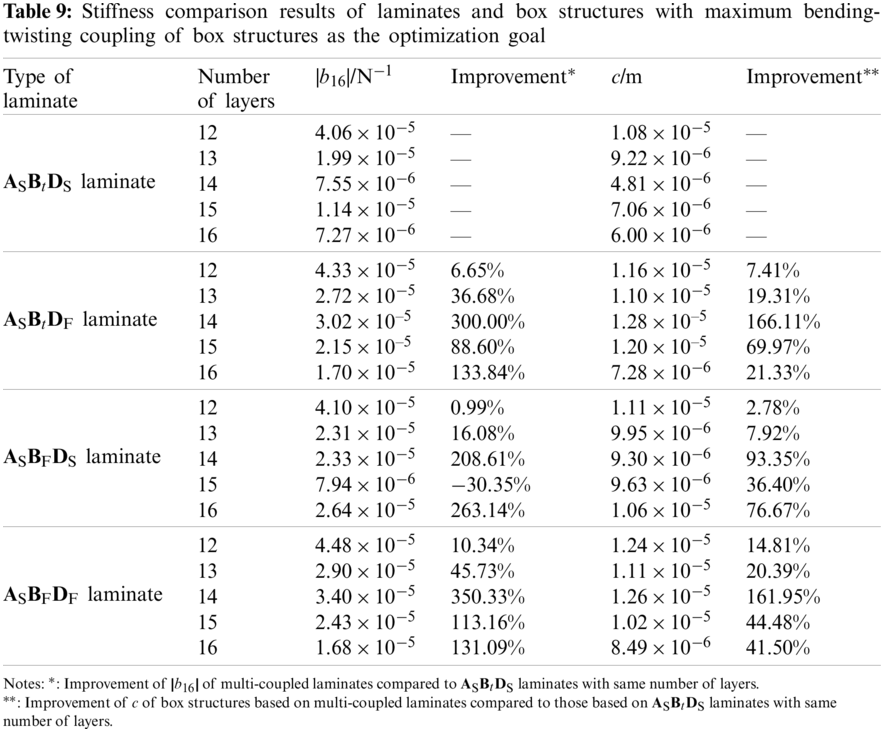
According to the optimization results in Tables 3–6, the comparison results of the extension-twisting coupling of laminates and the bending-twisting coupling of box structures were summarized, as shown in Tables 8 and 9.
The results show that: (1) Compared with the single-coupled ASBtDS laminate, the multi-coupled laminates (ASBtDF laminate, ASBFDS laminate and ASBFDF laminate) have a higher extension-twisting coupling, in which the extension-twisting coupling of 14-ply ASBtDF laminate is the maximum, reaching 456.95%; (2) For ASBtDS laminate, the same optimization results were obtained when optimizing with the maximum |b16| and c as objectives, which verified that the extension-twisting coupling of single coupled laminate was the decisive factor that constituted the bending-twisting coupling of box structure; (3) Compared with the box structures based on ASBtDS laminates, the torsion deformations of box structures based on multi-coupled laminates were significantly improved, wherein, the box structure composed of 14-ply ASBtDF laminate is the most obvious (increased to 266.11%), indicating that multi-couplings will obviously improve the bending-twisting coupling of box structure; (4) Comparing the box structures composed of multi-coupled laminates with the same number of layers and the type of coupling in Tables 8 and 9, it can be found that the extension-twisting coupling of laminates becomes smaller but the torsion deformation of the box structure still increases. Taking the box structure composed of 15-ply ASBFDS laminate as an example, when |b16| of laminate changed from 1.33 × 10⁻⁵ N−1 to 7.94 × 10⁻⁶ N−1, the c of box structure changed from 6.08 × 10⁻⁶ m to 9.63 × 10⁻⁶ m, indicating that other couplings except for the extension-twisting coupling (i.e., shearing-twisting and extension-bending) have the potential to enhance the bending-twisting coupling of box structure.
When the axial external load of laminate increases gradually, the destruction will occur first on one lamina. This will affect the rigidity of the entire laminate, and may cause further damage to other laminae. Thus, the failure load should be considered during the design process. The tension and compression external loads of first ply failure
Then, the strain of each lamina is expressed as
and the principal stresses of each lamina is expressed as
where,
The choice of strength theory depends on the actual laminate composite material. Studies have shown that for glass fiber/epoxy composite materials and composite materials with the same tensile strength and compressive strength, the Hill-Tsai strength theory is close to the experimental value in both qualitative and quantitative aspects, while the Tsai-Wu criterion is suitable for composite materials with different tensile and compressive strengths [25]. Because the tensile and compressive strength of lamina made of carbon fiber/epoxy prepreg are different, the Tsai-Wu strength criterion should be more applicable for the strength prediction. The principal stress of each lamina satisfies the relationships of
where, Xt(c) and Yt(c) represent the axial and transverse tensile (compressive) strength of lamina, S represents the shear strength. Because the value of F12 in the Tsai-Wu strength criterion is not easy to be determined, the Tsai-Wu quadratic failure criterion based upon the generalized von Mises isotropic criterion is used here to take the value of F12 [26]. The advantage of this widely used value method is its accuracy and relative simplicity [27,28].
Substituting the paving angle of each lamina into the stiffness equation, we can obtain the flexibility matrix coefficient of laminates. Then, combining Eqs. (29)–(31) with Eq. (33) gives the value of the external load Nmax(k) at which each lamina fails. At this time, the external load Nmax(k) corresponding to the k-ply lamina has two solutions: the positive solution Nmax1(k) is the maximum tensile load, and the negative solution Nmax2(k) is the maximum compressive load. Then,
where
Taking the laminates with maximum |b16| as examples in Tables 3–6, the
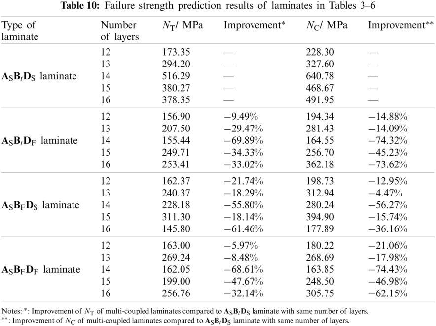
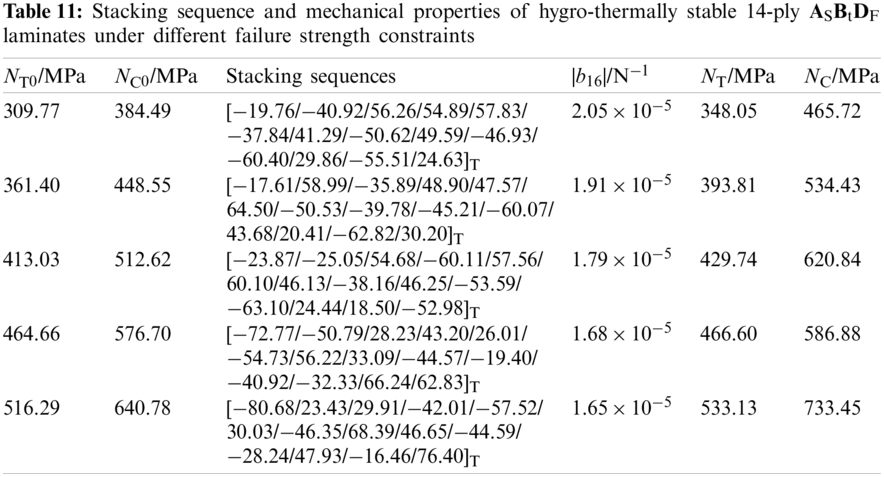
However, the negative impact of strength performance can be minimized through reasonable paving methods. Taking 14-ply ASBtDF laminate as an example, whose failure strengths
Table 11 shows the stacking sequence and mechanical properties of 14-ply ASBtDF laminates, mainly including extension-twisting couplings and failure strength. The hygro-thermal stability and extension-twisting coupling were verified by numerical simulation. The results demonstrate that: (1) The failure strength of the optimized laminate meets the requirement of lower limit; (2) As NT0 and
With the increase of the in-plane compression load, the multi-coupled laminate entered an unstable equilibrium. Once the load continued to increase, buckling occurred, which further affected the mechanical properties. Multi-couplings may increase the out-of-plane deformation under the in-plane load, which will lead to earlier buckling. Thus, it is very important to determine the influence of multiple coupling on the buckling load.
The analytical solution of buckling load
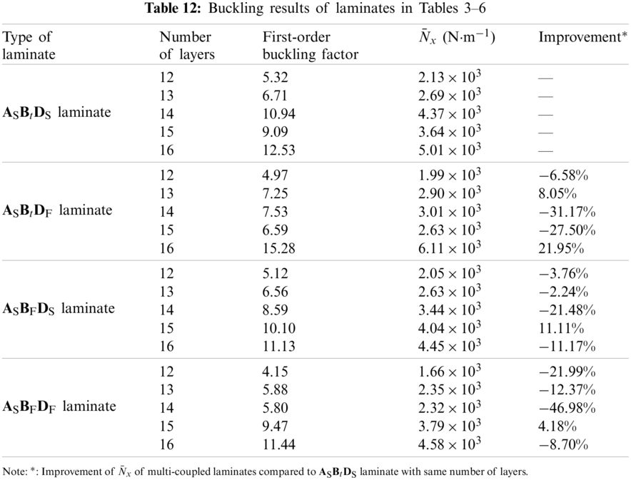
Taking the laminates with maximum |b16| as examples in Tables 3–6, the size, force and boundary conditions of laminate are consistent with laminates in Section 4.2. Table 12 shows the buckling performance of laminates, mainly including the buckling factors and corresponding buckling loads. The results demonstrate that: compared with the single extension-twisting coupled laminate, the buckling loads of multi-coupled laminates were reduced to varying degrees, illustrating the negative impact of multi-couplings on buckling loads.
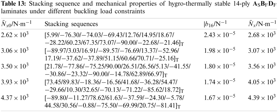
However, the negative impact of buckling can be minimized through reasonable paving design [13,17,20]. Actually, this problem can be equivalent to an optimization design problem with objective constraints. In view of the fact that the buckling load of laminate in this article was difficult to directly analytically express, the method of parametric modeling was also used to achieve this problem. Taking 14-ply ASBFDF laminate as an example, whose buckling load reduced the most (−46.98%), let us assume that the lower limits of the buckling load (
Table 13 shows the stacking sequence and mechanical properties of 14-ply ASBFDF laminates, mainly including extension-twisting couplings and buckling loads. The hygro-thermal stability and extension-twisting coupling have been verified by numerical simulation. The results demonstrate that: (1) The buckling load of the optimized laminate meets the requirement of lower limit; (2) With the increase of
There are four types of hygro-thermally stable laminates with extension-twisting coupling, including three multi-coupled laminates. They have the same thermal strain in the two main axis directions, which is only related to the material constant, the thermal material constant and the temperature difference. Multi-couplings significantly improve the extension-twisting coupling of laminates (up to 450%). At the same time, multi-couplings generally reduce the buckling load and failure strength. However, the negative impact can be minimized by reasonable paving methods. Furthermore, multi-coupled laminates have good robustness, and the bending-twisting coupling helps improve robustness.
The design optimization of the variable cross-section bending-twisting coupled box structure was achieved based on the multi-coupled laminates. The parametric modeling method is combined with finite element method to achieve high precision and high efficiency of optimal design. The multi-couplings of laminates can obviously improve the bending-twisting coupling of box structure (up to be more than 260%). The design method is applicable to other types of laminates. The optimal design method can also be extended to the static deformation of composite structures with arbitrary complex configurations.
Funding Statement: The authors disclosed receipt of the following financial support for the research, authorship, and/or publication of this article: the National Natural Science Foundation of China (Grant No. 11472003), the Natural Science Foundation of Hunan Province of China (Grant No. 2021JJ30770) and the Postgraduate Scientific Research Innovation Project of Hunan Province (Grant No. CX20200007).
Conflicts of Interest: The authors declare that they have no conflicts of interest to report regarding the present study.
1. Song, O., Kwon, H. D., Librescu, L. (2007). Modelling and vibration of a non-classical tilt-rotor wing system. Aeronautical Journal, 111(1119), 285–295. DOI 10.1017/S000192400000453X. [Google Scholar] [CrossRef]
2. Santer, M., Pellegrino, S. (2009). Topological optimization of compliant adaptive wing structure. AIAA Journal, 47(3), 523–534. DOI 10.2514/1.36679. [Google Scholar] [CrossRef]
3. Berry, D. S., Ashwill, T., Chen, H. P. (2003). Study of hygrothermal isotropic layup and hygrothermal curvature-stable coupling composite laminates. 44th AIAA/ASME/ASCE/AHS/ASC Structures, Structural Dynamics, and Materials Conference, Norfolk, VA. DOI 10.2514/6.2003-1506. [Google Scholar] [CrossRef]
4. Berry, D. S., Ashwill, T. (2007). Design of 9-meter carbon-fiberglass prototype blades: CX-100 and TX-100. Sandia National Laboratories Report, No. SAND2007-0201. TPI Composites, Inc. [Google Scholar]
5. Moore, M., Frei, D. (1983). X-29 forward swept wing aerodynamic overview. Applied Aerodynamics Conference, Danvers, MA, USA. DOI 10.2514/6.1983-1834. [Google Scholar] [CrossRef]
6. York, C. B. (2015). On extension-shearing coupled laminates. Composite Structures, 120, 472–482. DOI 10.1016/j.compstruct.2014.10.019. [Google Scholar] [CrossRef]
7. Haynes, R. A., Armanios, E. A. (2010). New families of hygrothermally stable composite laminates with optimal extension-twist coupling. AIAA Journal, 48(12), 2954–2961. DOI 10.2514/1.J050596. [Google Scholar] [CrossRef]
8. Apte, A. P., Haynes, R. A., Wang, B. P., Erian, A. A. (2010). Design of optimal hygrothermally stable laminates with bending-twist coupling by ant colony optimization. 13th AIAA/ISSMO Multidisciplinary Analysis Optimization Conference Fort Worth, Texas. DOI 10.2514/6.2010-9180. [Google Scholar] [CrossRef]
9. Winckler, S. J. (1985). Technical notes: Hygrothermally curvature stable laminates with tension-torsion coupling. Journal of the American Helicopter Society, 30(3), 56–58. DOI 10.4050/JAHS.30.56. [Google Scholar] [CrossRef]
10. Cross, R. J., Haynes, R. A., Armanios, E. A. (2008). Families of hygrothermally stable asymmetric laminated composites. Journal of Composite Materials, 42(7), 697–716. DOI 10.1177/0021998308088597. [Google Scholar] [CrossRef]
11. Haynes, R. A., Armanios, E. A. (2012). The challenge of achieving hygrothermal stability in composite laminates with optimal couplings. International Journal of Engineering Science, 59, 74–85. DOI 10.1016/j.ijengsci.2012.03.013. [Google Scholar] [CrossRef]
12. York, C. B. (2013). Tapered hygro-thermally curvature-stable laminates with non-standard ply orientations. Composites Part A: Applied Science and Manufacturing, 44(1), 140–148. DOI 10.1016/j.compositesa.2012.08.023. [Google Scholar] [CrossRef]
13. York, C. B., Almeida, S. F. M. (2017). On extension-shearing bending-twisting coupled laminates. Composite Structures, 164, 10–22. DOI 10.1016/j.compstruct.2016.12.041. [Google Scholar] [CrossRef]
14. York, C. B., Almeida, S. F. M. (2017). Tapered laminate designs for new non-crimp fabric architectures. Composites Part A: Applied Science and Manufacturing, 100, 150–160. DOI 10.1016/j.compositesa.2017.04.023. [Google Scholar] [CrossRef]
15. York, C. B. (2017). On bending-twisting coupled laminates. Composite Structures, 160, 887–900. DOI 10.1016/j.compstruct.2016.10.063. [Google Scholar] [CrossRef]
16. Li, J., Li, D. K. (2015). Extension-shear coupled laminates with immunity to hygro-thermal shearing distortion. Composite Structures, 123, 401–407. DOI 10.1016/j.compstruct.2014.12.032. [Google Scholar] [CrossRef]
17. Li, J., Li, D. K. (2014). Multi-objective optimization of hygro-thermally curvature-stable antisymmetric laminates with extension-twist coupling. Journal of Mechanical Science and Technology, 28(4), 1373–1380. DOI 10.1007/s12206-013-1171-y. [Google Scholar] [CrossRef]
18. Cui, D., Li, D. K. (2019). Bending-twisting coupled structures based on composite laminates with extension-shear coupling effect. Composite Structures, 209(1), 434–442. DOI 10.1016/j.compstruct.2018.09.095. [Google Scholar] [CrossRef]
19. Cui, D., Li, D. K. (2018). Optimization of hybrid laminates with extension-shear coupling. International Journal of Aerospace Engineering, 2018, 1–12. DOI 10.1155/2018/9869105. [Google Scholar] [CrossRef]
20. York, C. B., Almeida, S. F. M. (2018). Effect of bending-twisting coupling on the compression and shear buckling strength of infinitely long plates. Composite Structures, 184, 18–29. DOI 10.1016/j.compstruct.2017.09.085. [Google Scholar] [CrossRef]
21. Jones, R. M. (1999). Mechanics of composite materials. Boca Raton: CRC Press. [Google Scholar]
22. Cui, D., Li, D. K., Zhou, S. M. (2018). Hygro-thermally curvature-stable free-layer composite laminates with extension-twist coupling. Advanced Composites Letters, 27(3), 108–113. DOI 10.1177/096369351802700303. [Google Scholar] [CrossRef]
23. Cui, D., Li, D. K. (2020). An adaptive structure based on hybrid extension-twisting coupled laminates. Mechanics of Composite Materials, 56(5), 601–618. DOI 10.1007/s11029-020-09907-0. [Google Scholar] [CrossRef]
24. Krone, N. J. (1974). Divergence elimination with advanced composites. Aircraft Systems and Technology Meeting, Los Angeles, CA, USA. DOI 10.2514/6.1975-1009. [Google Scholar] [CrossRef]
25. Kolisch, R., Hartmann, S. (2006). Experimental investigation of heuristics for resource-constrained project scheduling: An update. European Journal of Operational Research, 174(1), 23–37. DOI 10.1016/j.ejor.2005.01.065. [Google Scholar] [CrossRef]
26. Tsai, S. W., Hahn, H. T. (1980). Introduction to composite materials. Westport, Connecticut: Technomic Publishing Company, Inc. [Google Scholar]
27. Pang, S. S., Pandian, A., Bradshaw, R. D. (1992). Modified Tsai-Wu failure criterion for fiber-reinforced composite laminates. Polymer Composites, 13(4), 273–277. DOI 10.1002/(ISSN)1548-0569. [Google Scholar] [CrossRef]
28. Majak, J., Hannus, S. (2003). Orientational design of anisotropic materials using the hill and Tsai-Wu strength criteria. Mechanics of Composite Materials, 39(6), 509–520. DOI 10.1023/B:MOCM.0000010623.38596.3e. [Google Scholar] [CrossRef]
 | This work is licensed under a Creative Commons Attribution 4.0 International License, which permits unrestricted use, distribution, and reproduction in any medium, provided the original work is properly cited. |