| Computer Modeling in Engineering & Sciences |
DOI: 10.32604/cmes.2021.017204
ARTICLE
Ideal Drift Response Curve for Robust Optimal Damper Design for Elastic-Plastic MDOF Structures under Multi-Level Earthquakes
Dedicated to Professor Karl S. Pister for his 95th birthday
Department of Architecture and Architectural Engineering, Graduate School of Engineering, Kyoto University, Kyotodaigaku-Katsura, Nishikyo, Kyoto, 615-8540, Japan
*Corresponding Author: Izuru Takewaki. Email: takewaki@archi.kyoto-u.ac.jp
Received: 22 April 2021; Accepted: 18 June 2021
Abstract: A new method of robust damper design is presented for elastic-plastic multi-degree-of-freedom (MDOF) building structures under multi-level ground motions (GMs). This method realizes a design that is effective for various levels of GMs. The robustness of a design is measured by an incremental dynamic analysis (IDA) curve and an ideal drift response curve (IDRC). The IDRC is a plot of the optimized maximum deformation under a constraint on the total damper quantity vs. the design level of the GMs. The total damper quantity corresponds to the total cost of the added dampers. First, a problem of generation of IDRCs is stated. Then, its solution algorithm, which consists of the sensitivity-based algorithm (SBA) and a local search method, is proposed. In the application of the SBA, the passive added dampers are removed sequentially under the specified-level GMs. On the other hand, the proposed local search method can search the optimal solutions for a constant total damper quantity under GMs’ increased levels. In this way, combining these two algorithms enables the comprehensive search of the optimal solutions for various conditions of the status of the GMs and the total damper quantity. The influence of selecting the type of added dampers (oil, hysteretic, and so on) and the selection of the input GMs on the IDRCs are investigated. Finally, a robust optimal design problem is formulated, and a simple local search-based algorithm is proposed. A simple index using the IDRC and the IDA curve of the model is used as the objective function. It is demonstrated that the proposed algorithm works well in spite of its simplicity.
Keywords: Optimal damper placement; robust damper design; multi-level earthquake; ideal drift response curve elastic-plastic MDOF model; viscous damper; hysteretic damper
Building structures are designed under various uncertainties, e.g., modeling errors and incomplete reported data on geometrical and mechanical properties of structural elements and ground supporting the building. Excessive pursuit of the profitability regarding structural design may lead to a design with a low resistance to natural disasters. Experienced designers can balance the profitability and the effect of these uncertainties based on their deep understanding of structural mechanism. On the other hand, the reliability-based design and the robustness-based design are mathematical ways to deal with such uncertainties directly. Many researches on these design methods and the evaluation of robustness of structures have been accumulated so far [1–7]. The performance-based design is also one of the structural design methods which take account of uncertainties. Incremental dynamic analysis (IDA) [8] is often used to make fragility curves of structures for the increasing level of earthquake ground motions.
Many researchers have tackled the problems of optimal passive dampers (for example, see [9 –11]). Zhang et al. [12] and Garcia [13] developed a simple design procedure for viscoelastic dampers. Takewaki [14] introduced an optimality criteria-based algorithm to minimize the sum of the inter-story drifts under a harmonic excitation with the fundamental natural frequency of the structure. This approach was extended to the base shear response for seismic rehabilitation of planar building structures [15]. Trombetti et al. [16] investigated the effectiveness of mass-proportional damping systems using a finite element model. Whittle et al. [17] compared several methods for optimal damper placement in view of reductions in peak responses, the usability of the methods and the computational effort. Martínez et al. [18] formulated a problem of optimal hysteretic damper placement in the frequency domain using the stochastic equivalent linearization technique. Aydin et al. [19] tackled a problem of optimal damper placement considering the soil-structure interaction. Metaheuristics have been applied widely to the optimal damper placement [20–23]. Some researchers treated simultaneous optimization problems of main structures and added dampers [24,25].
The awareness of the significance of treating elastic-plastic structures in the optimal damper placement has been prevailing recently [25–30]. Since the setting of the input ground motions (GMs) level used for the optimization affects the final design, the level should be determined carefully. For example, a model optimized under lower-level GMs may exhibit large plastic deformation concentrations in specific stories for larger-level GMs [25,31]. However, the model optimized under a quite large level of GMs may not reduce the responses effectively for lower-level GMs. Moreover, earthquakes which will hit buildings are unpredictable. Therefore, an optimization method is needed which can properly deal with the uncertainty of the level of GMs.
This paper presents a new method of robust damper design for elastic-plastic multi-degree-of-freedom (MDOF) building structures under multi-level GMs. This method realizes a design that is effective for various levels of GMs. The robustness of such design is measured by an IDA curve [8] and an ideal drift response curve (IDRC) [32]. The IDRC is a plot of the optimized maximum deformation under a constraint on the total damper quantity versus the design level of the GMs. The total damper quantity corresponds to the total cost of the added dampers. A problem of generation of IDRCs is stated and its solution algorithm is proposed. The influence of selecting the type of added dampers (oil, hysteretic,
2 Problem of Generation of IDRCs
This section explains the concept of robust damper design based on an ideal drift response curve (IDRC). Then the generalized problem of optimal damper placement under consecutive-level GMs (G-PODPCG) is stated as an extended version of the problem presented by Akehashi et al. [32]. Finally, its solution algorithm, consisting of the sensitivity-based algorithm (SBA) and a local search method, is proposed.
2.1 IDRC and Concept of Robust Damper Design
Akehashi et al. [32] proposed an IDRC, which is a new concept on the optimal damper placement for elastic-plastic MDOF structures to visually capture effectiveness of a damper design for various levels of GMs (Fig. 1a).
where
Fig. 1b shows the difference between the robust damper design based on the IDRC and the non-robust damper designs. The IDA curves of the non-robust damper designs are plotted locally away from the IDRC. This results from the correspondence of the equivalent natural periods of the designs and the predominant periods of the input GMs. On the other hand, the IDA curve of the robust damper design runs near the IDRC. This means that the design is effective for various levels of the input GMs.
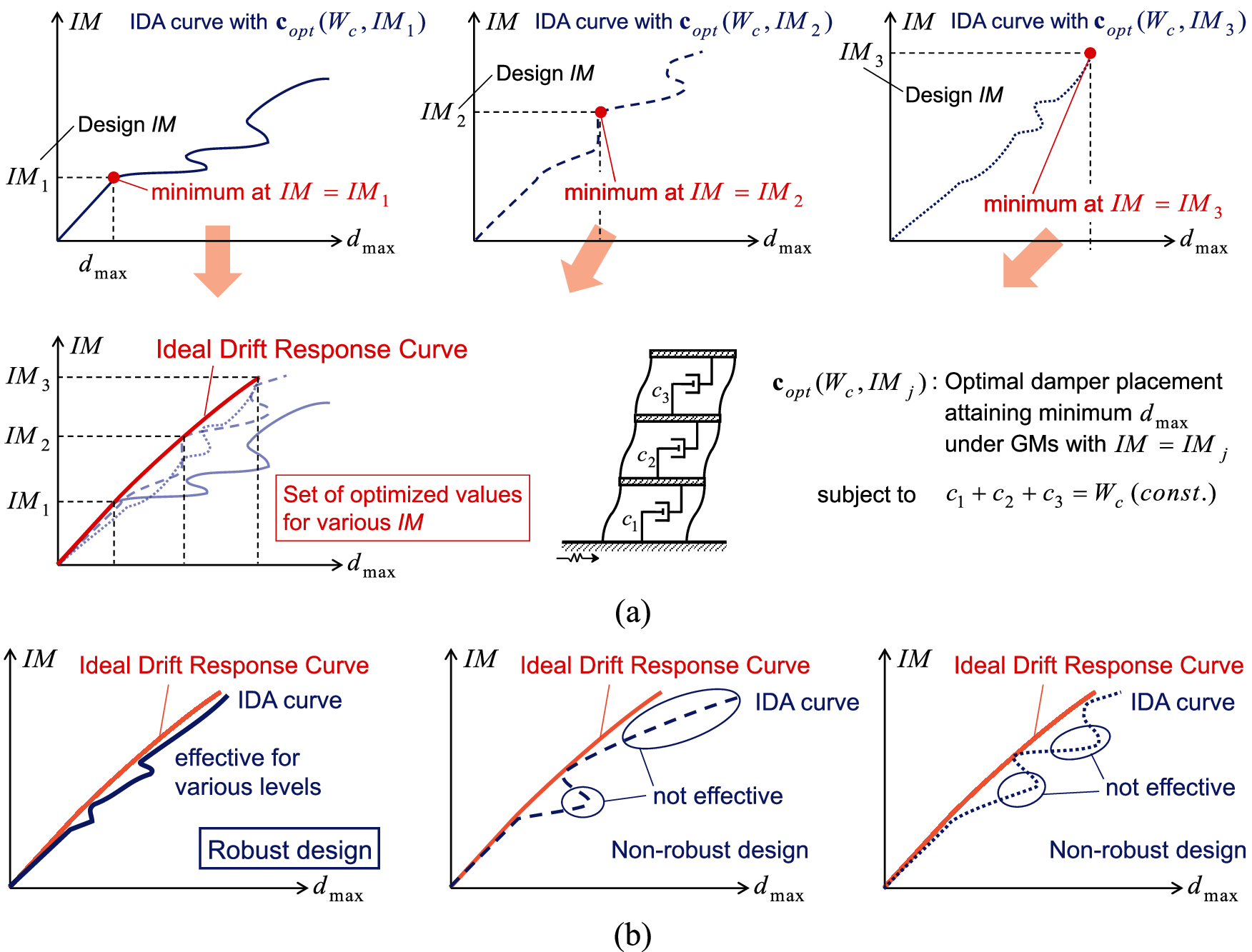
Figure 1: Concept of IDRC and robust damper design, (a) IDRC, (b) robust damper design and non-robust damper design
2.2 Formulation of Problem of Generation of IDRC
The IDRC of the viscous dampers W = Wc is obtained by solving the following problem.
[Problem of Optimal Damper Placements for Consecutive-Level GMs (PODPCG)]
Obtain the nL sets of damper placements
Akehashi et al. [32] proposed a consecutive design generation method (CDGM) as the solution algorithm for the problem PODPCG. In this paper, an extended version of the problem PODPCG, a generalized PODPCG (G-PODPCG) is treated.
[Generalized PODPCG (G-PODPCG)]
Obtain the nD sets of IDRCs with
It is noted that the value of IM becomes large when the number of the subscript of IM becomes large, although the value of W becomes small when the number of the subscript of W becomes large.
The solution algorithm for the problem G-PODPCG may be described as follows:
[Algorithm: Advanced Consecutive Design Generation Method (A-CDGM)]
Step 1 Set an initial design
Step 2 Obtain
Step 3 Put
Step 4 Obtain
Step 5 Update
Step 6 Update
Step 7 Update
[Sensitivity-Based Algorithm (SBA)]
Step 1 Put and
Step 2 Put
Step 3 Update
Step 4 Evaluate the sensitivity
Step 5 Find the minimum value of
Step 6 If , then finalize the process. If , return to Step 2.
It is noted that the local search method adopted in this paper can be described as follows:
[Local Search]
Step 1 Set
Step 2 Find the story i which exhibits the largest value of the interstory drift.
Step 3 Find the story
Step 4 Update
Fig. 2 shows the overview and the schematic diagram of the proposed solution algorithm. The proposed algorithm consists of the SBA and the local search method. In the application of the SBA, the inactive added dampers are removed sequentially under the specified-level GMs. On the other hand, the proposed local search method can search the optimal solutions with a constant sum of added damping coefficients under the increased levels of the GMs. Therefore, the combination of these two algorithms enables the comprehensive search of the optimal solutions for various conditions of the level of the GMs and the sum of the added damping coefficients.
It is also noted that the proposed algorithm is applicable to the optimal hysteretic damper placement. In such case, added damping coefficient of viscous dampers is replaced to added stiffness of hysteretic dampers.
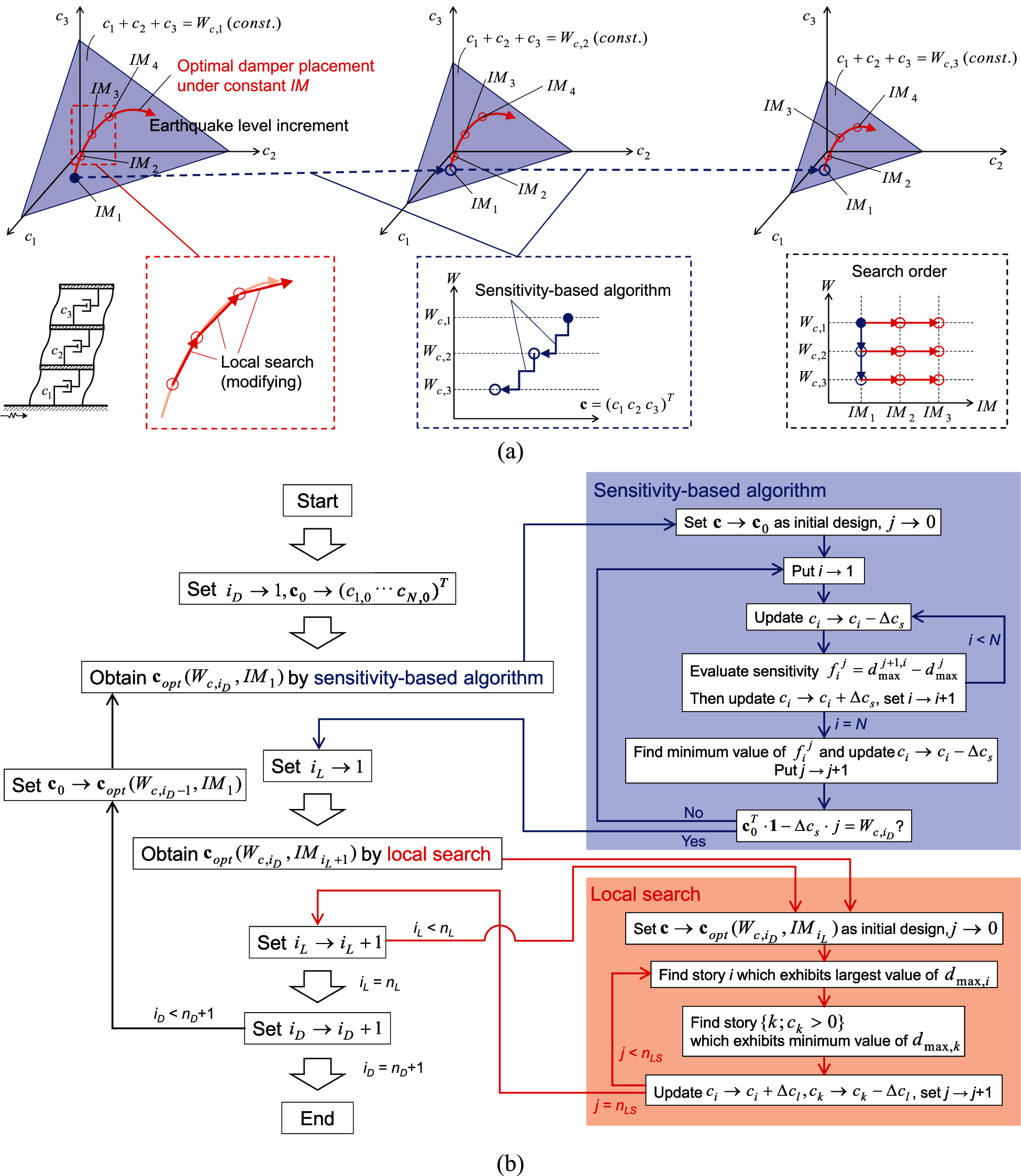
Figure 2: Overview and schematic diagram of A-CDGM, (a) overview, (b) schematic diagram
This section investigates the influence of the selection of the input GMs and the type of added dampers on the IDRCs. El Centro NS component during the Imperial Valley earthquake in 1940 and Rinaldi station fault-normal component during the Northridge earthquake in 1994 are employed here (Fig. 3). The former is a representative GM of random nature, and the latter is a representative GM of pulse type. The level of the GM is adjusted by the peak ground velocities (PGV). 51 levels of the GM (from PGV = 0.5 [m/s] to PGV = 1.5 [m/s] by the increment 0.02 [m/s]) are used. Linear viscous dampers are treated in Sections 3.2 and 3.3, and hysteretic dampers are treated in Sections 3.4 and 3.5.
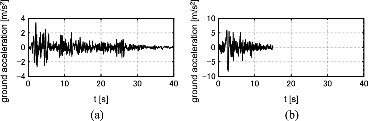
Figure 3: Earthquake ground motions adopted for numerical examples, (a) El centro NS component, (b) Rinaldi sta. FN component
Consider two shear building models of 12 stories with different story stiffness distributions. Model 1 has a trapezoidal distribution of story stiffnesses (k1/k12 = 4). Model 2 has a uniform distribution of story stiffnesses. The undamped fundamental natural period of these two models is 1.2 [s] and the structural damping ratio is 0.01 (stiffness proportional type). All the floor masses have the same value. The common story height is 4 [m] and the common yield inter-story drift dy is 4/150 [m]. The story shear-interstory drift relation obeys the elastic perfectly-plastic rule.
3.2 Optimization of Viscous Damper Placement
The targeted values of the sum of the added damping coefficients are set to
Fig. 4 shows the IDRCs. It can be observed that the IDRCs are monotonically increasing with respect to PGV. In the case of
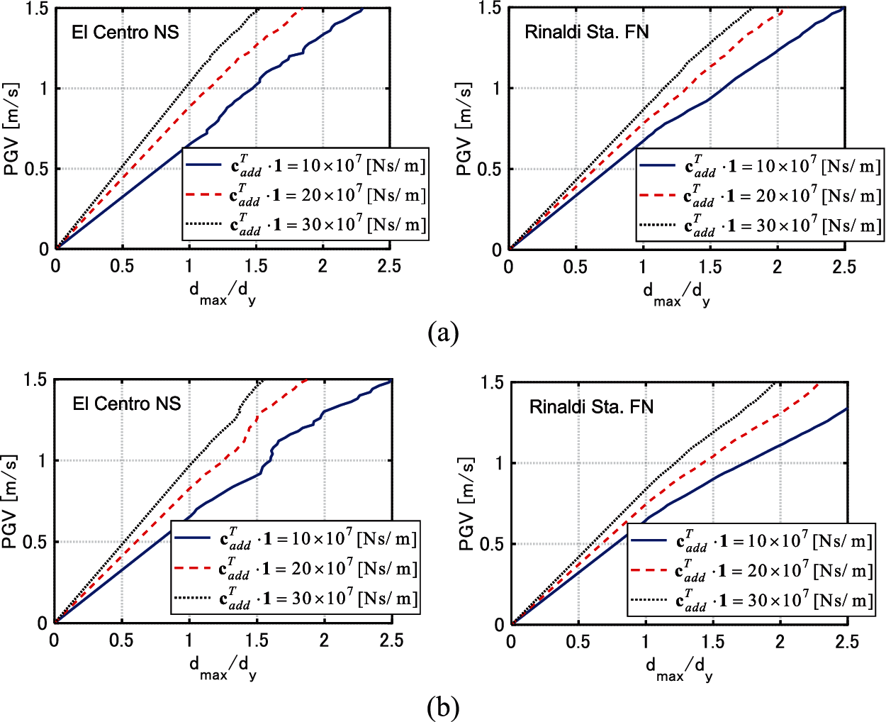
Figure 4: IDRCs of models with viscous dampers, (a) Model 1, (b) Model 2
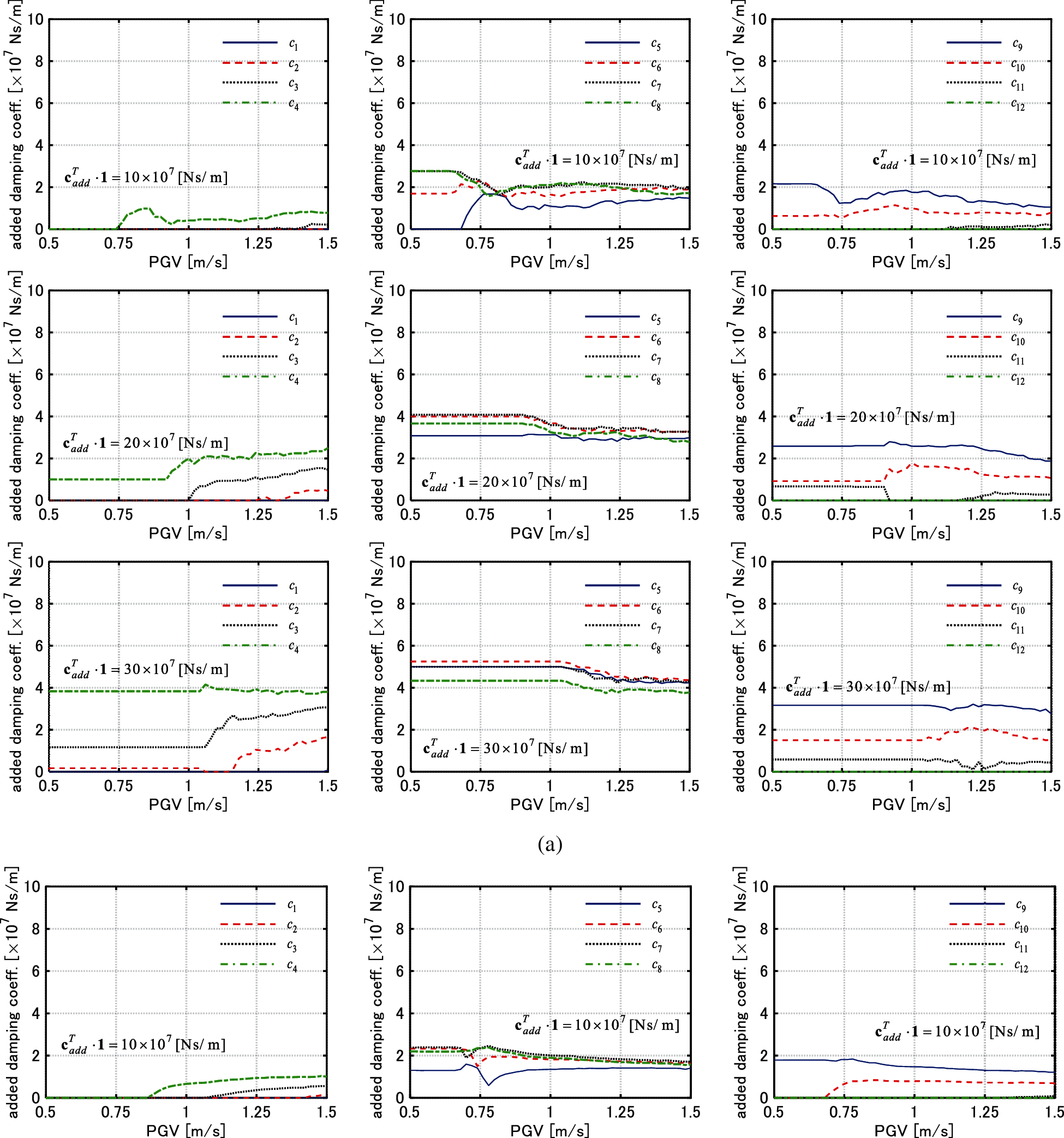
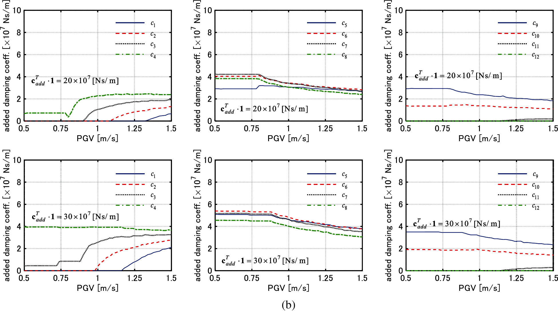
Figure 5: Change of added damping coefficient of each story with respect to PGV (Model 1), (a) El centro NS component, (b) Rinaldi sta. FN component
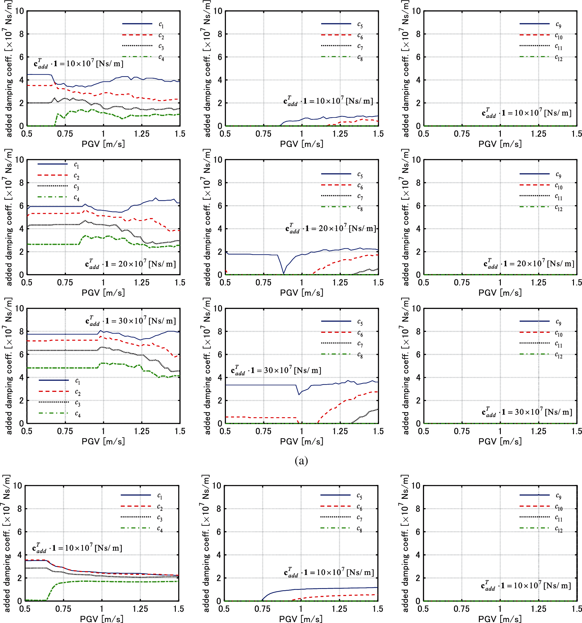
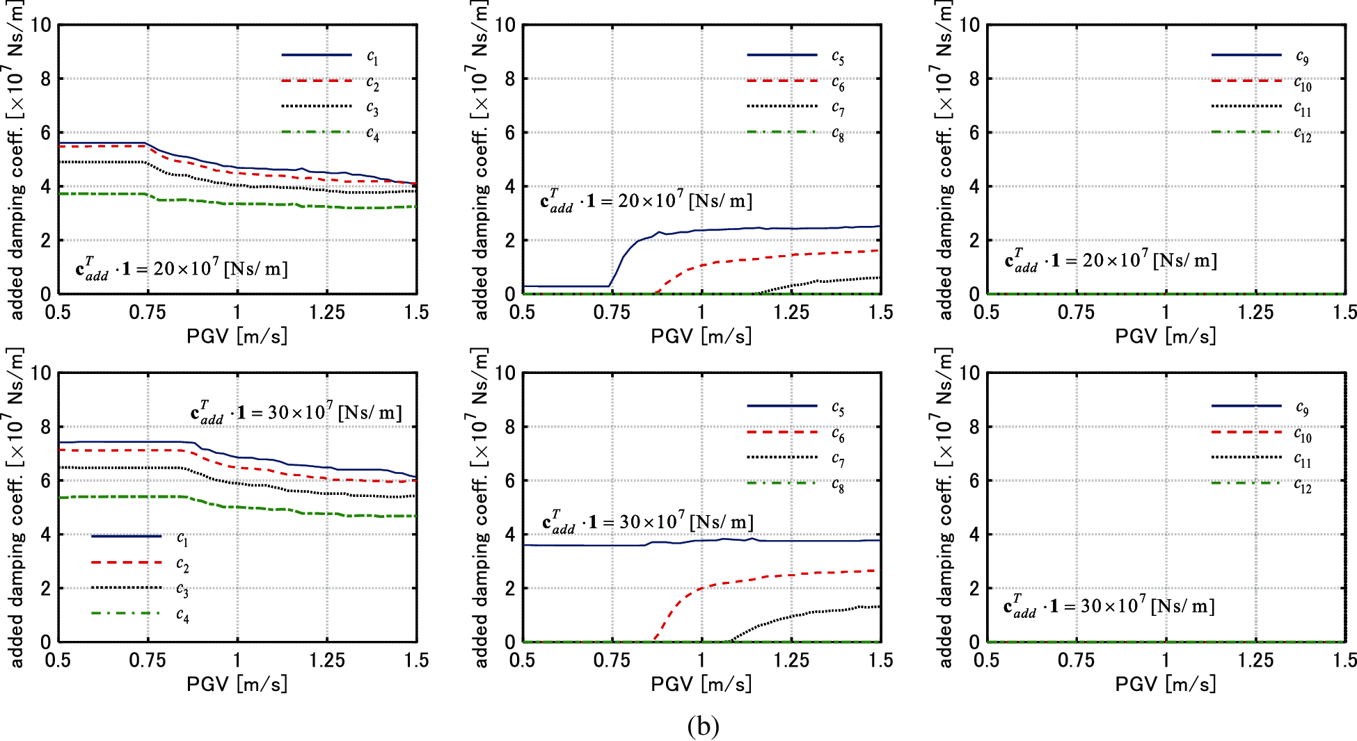
Figure 6: Change of added damping coefficient of each story with respect to PGV (Model 2), (a) El centro NS component, (b) Rinaldi sta. FN component
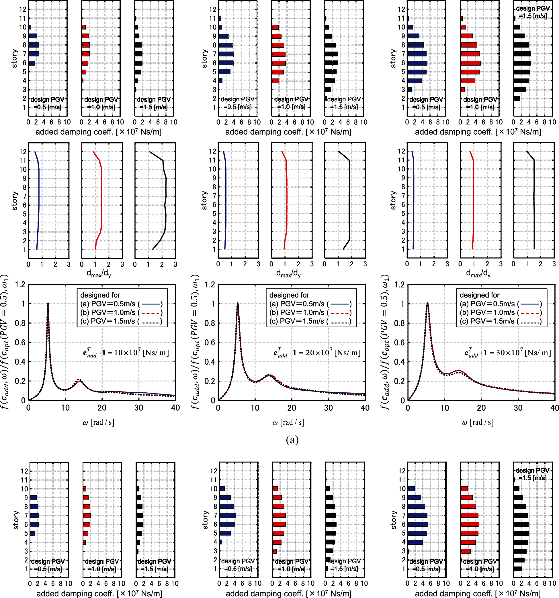
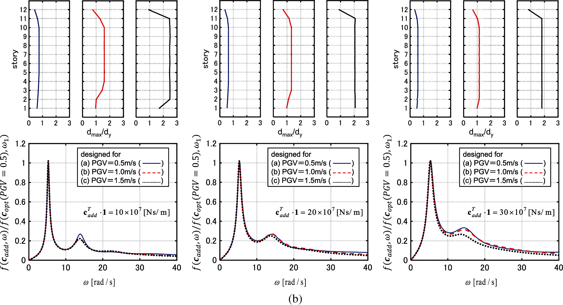
Figure 7: Distributions of added damping coefficient, distributions of interstory drifts and sum of transfer functions of interstory velocity (Model 1), (a) El centro NS component, (b) Rinaldi sta. FN component
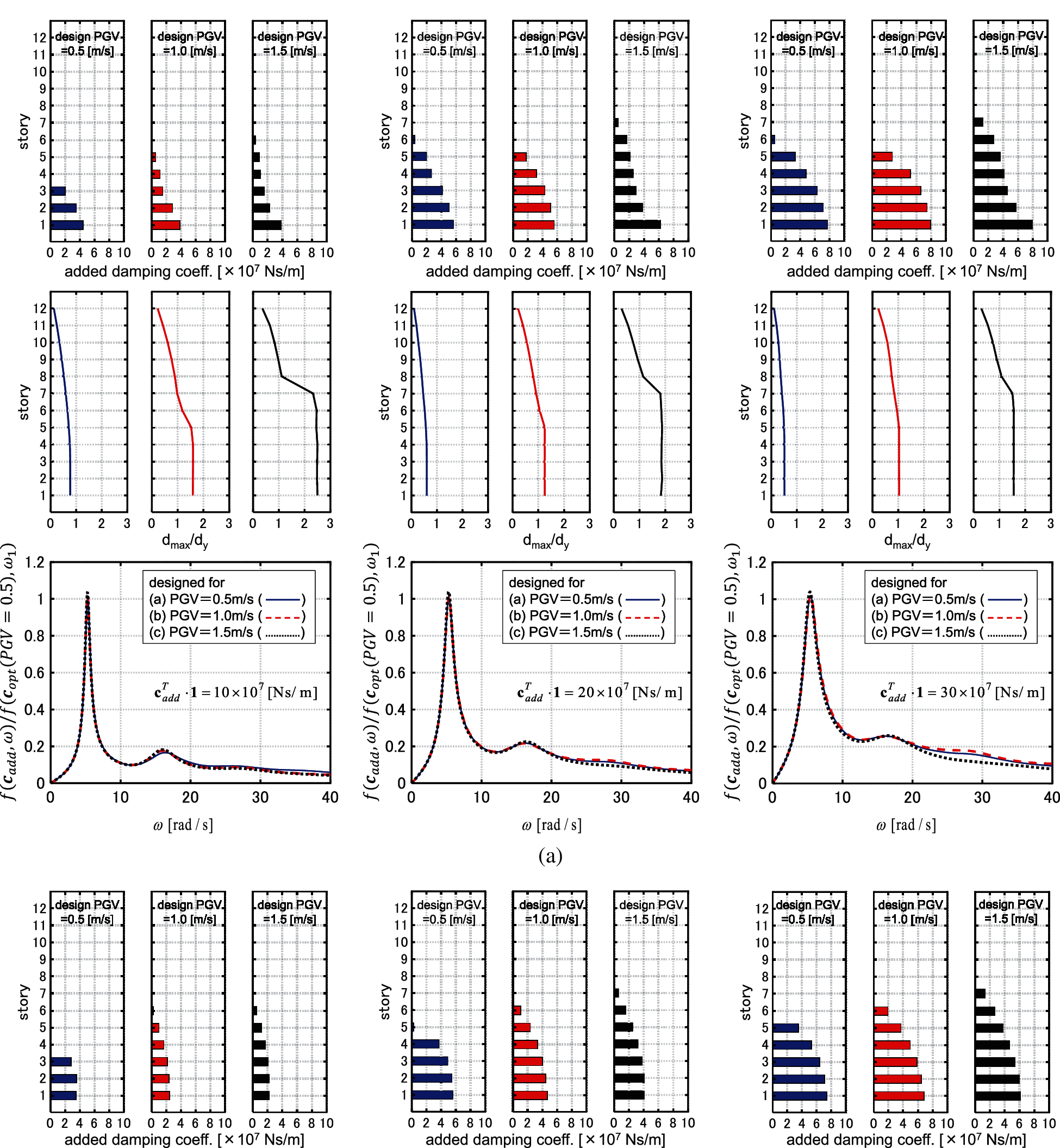
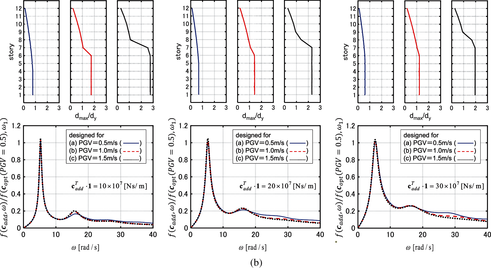
Figure 8: Distributions of added damping coefficient, distributions of interstory drifts and sum of transfer functions of interstory velocity (Model 2), (a) El centro NS component, (b) Rinaldi sta. FN component
3.3 IDA Analysis of Models with Optimally Designed Viscous Dampers
Fig. 9 shows the maximum interstory drift distributions by the IDA analysis for the models designed
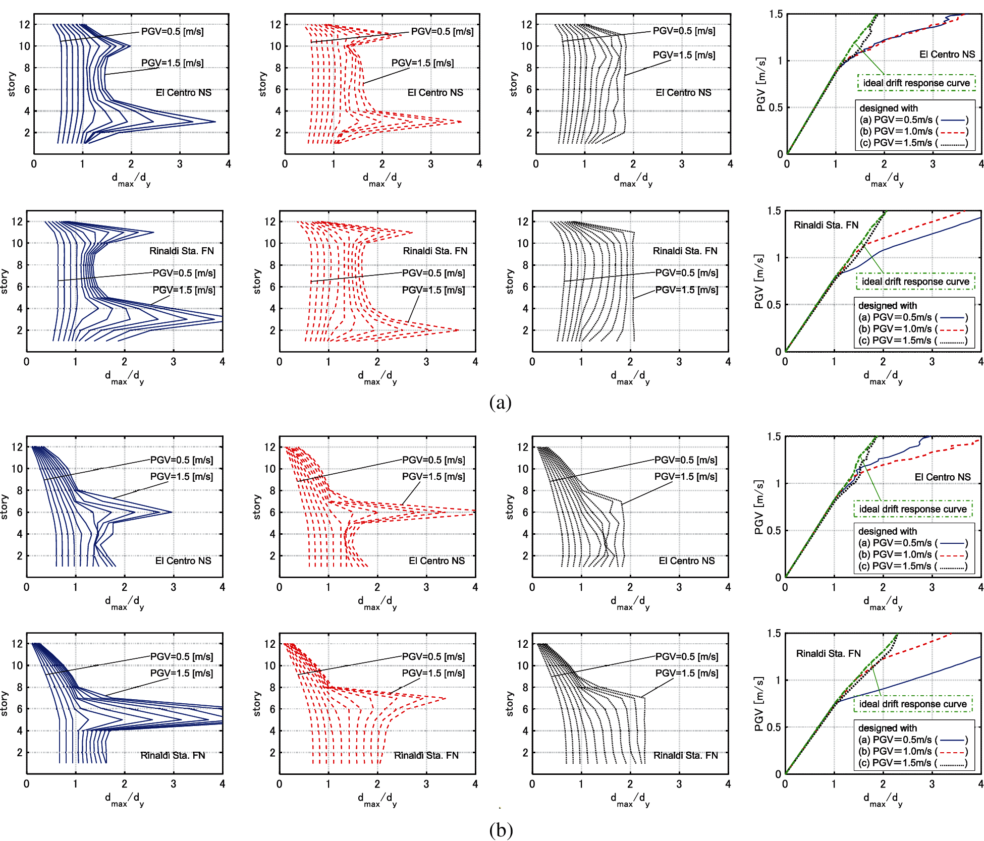
Figure 9: IDA analysis for 3 models designed under GMs with PGV = 0.5, 1.0, 1.5 [m/s] (
3.4 Optimization of Hysteretic Damper Placement
The yield deformations of hysteretic dampers are set to 4/800 [m]. The restoring force-deformation relation obeys the elastic perfectly-plastic rule. The target values of the sum of the added stiffnesses are set to
Fig. 10 shows the IDRCs. It can be observed that the IDRCs exhibit a roughly monotonic increase with respect to PGV. Unlike the cases of viscous dampers, the values of
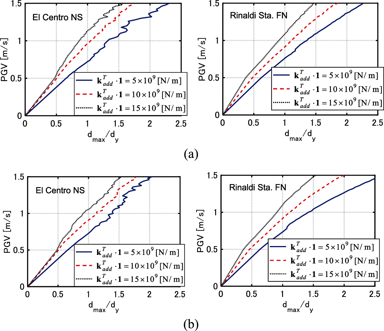
Figure 10: IDRCs of models with hysteretic dampers, (a) Model 1, (b) Model 2
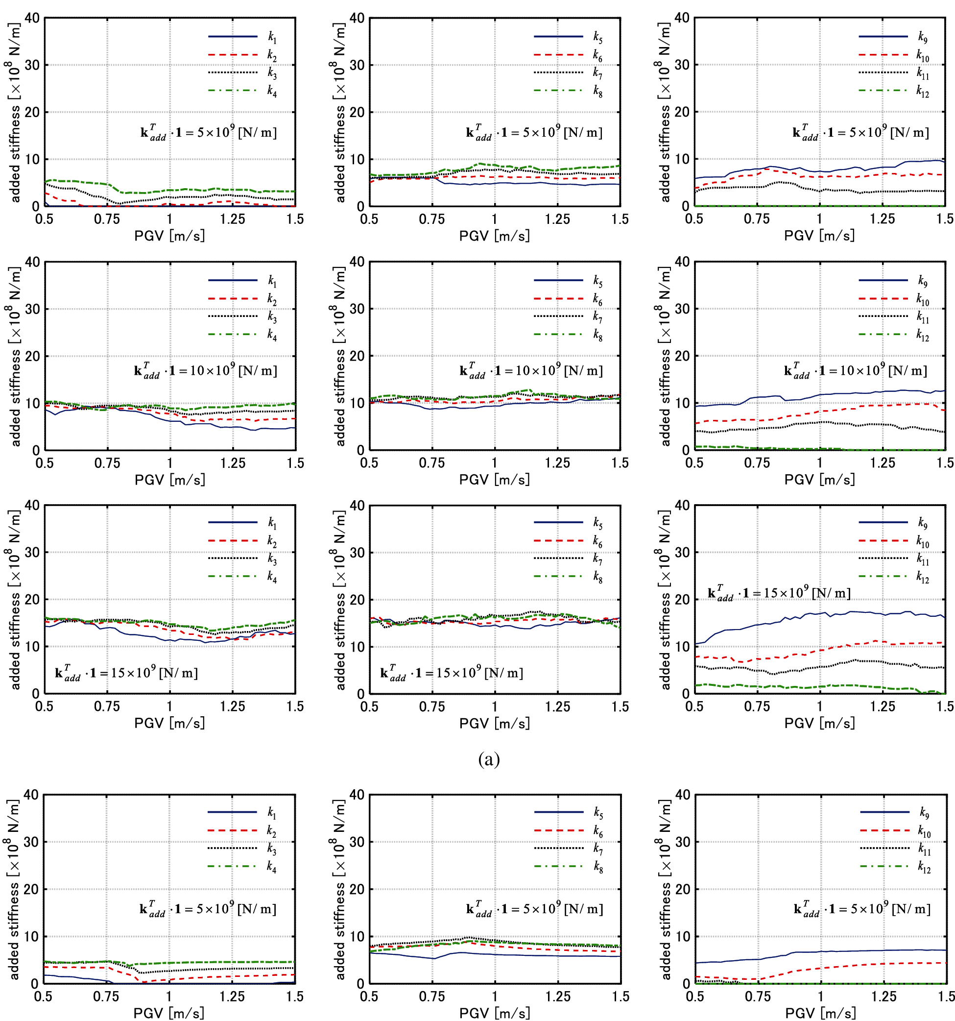

Figure 11: Change of added stiffness of each story with respect to PGV (Model 1), (a) El centro NS component, (b) Rinaldi sta. FN component
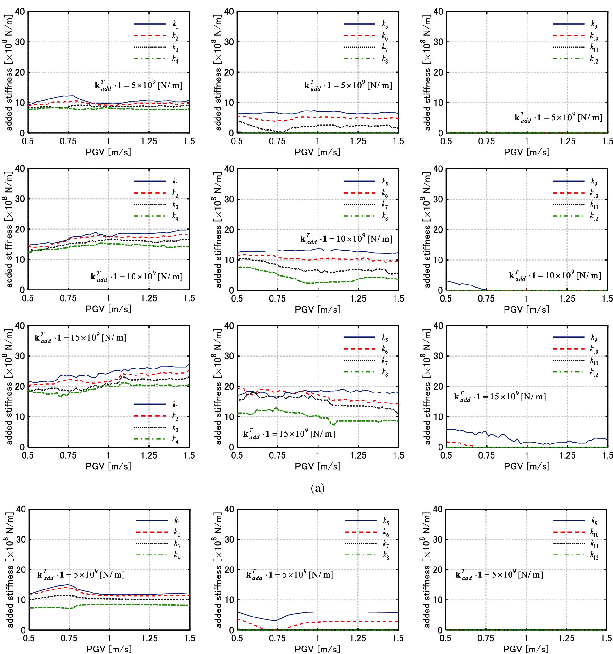

Figure 12: Change of added stiffness of each story with respect to PGV (Model 2), (a) El centro NS component, (b) Rinaldi sta. FN component
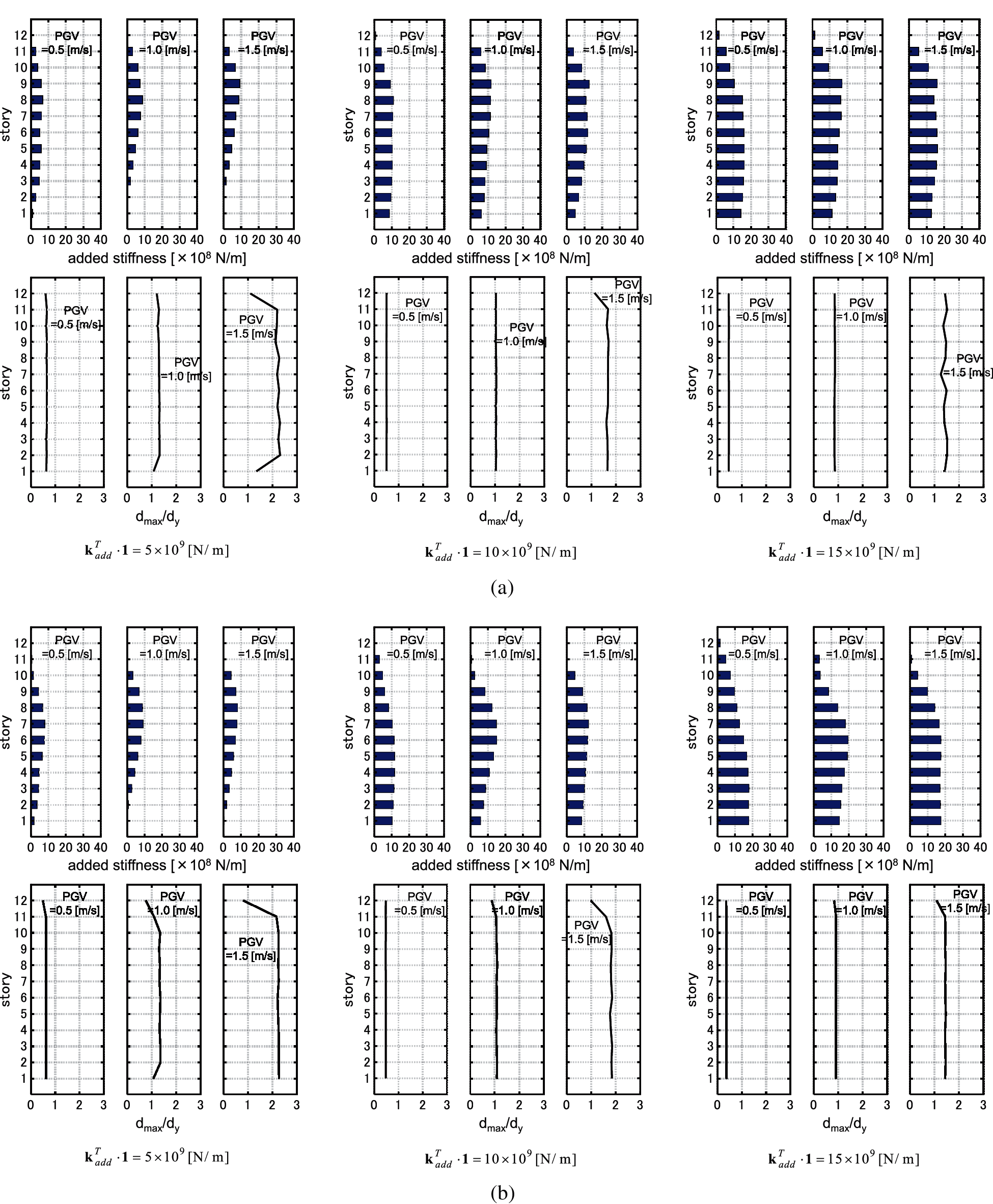
Figure 13: Distributions of added stiffness and distributions of interstory drifts (Model 1), (a) El centro NS component, (b) Rinaldi sta. FN component
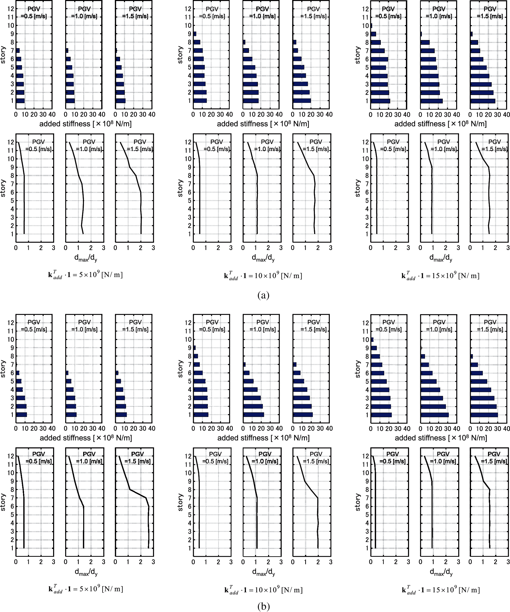
Figure 14: Distributions of added stiffness and distributions of interstory drifts (Model 2), (a) El centro NS component, (b) Rinaldi sta. FN component
3.5 IDA Analysis of Models with Optimally Designed Hyteretic Dampers
Fig. 15 shows the maximum interstory drift distributions by the IDA analysis for the models designed for
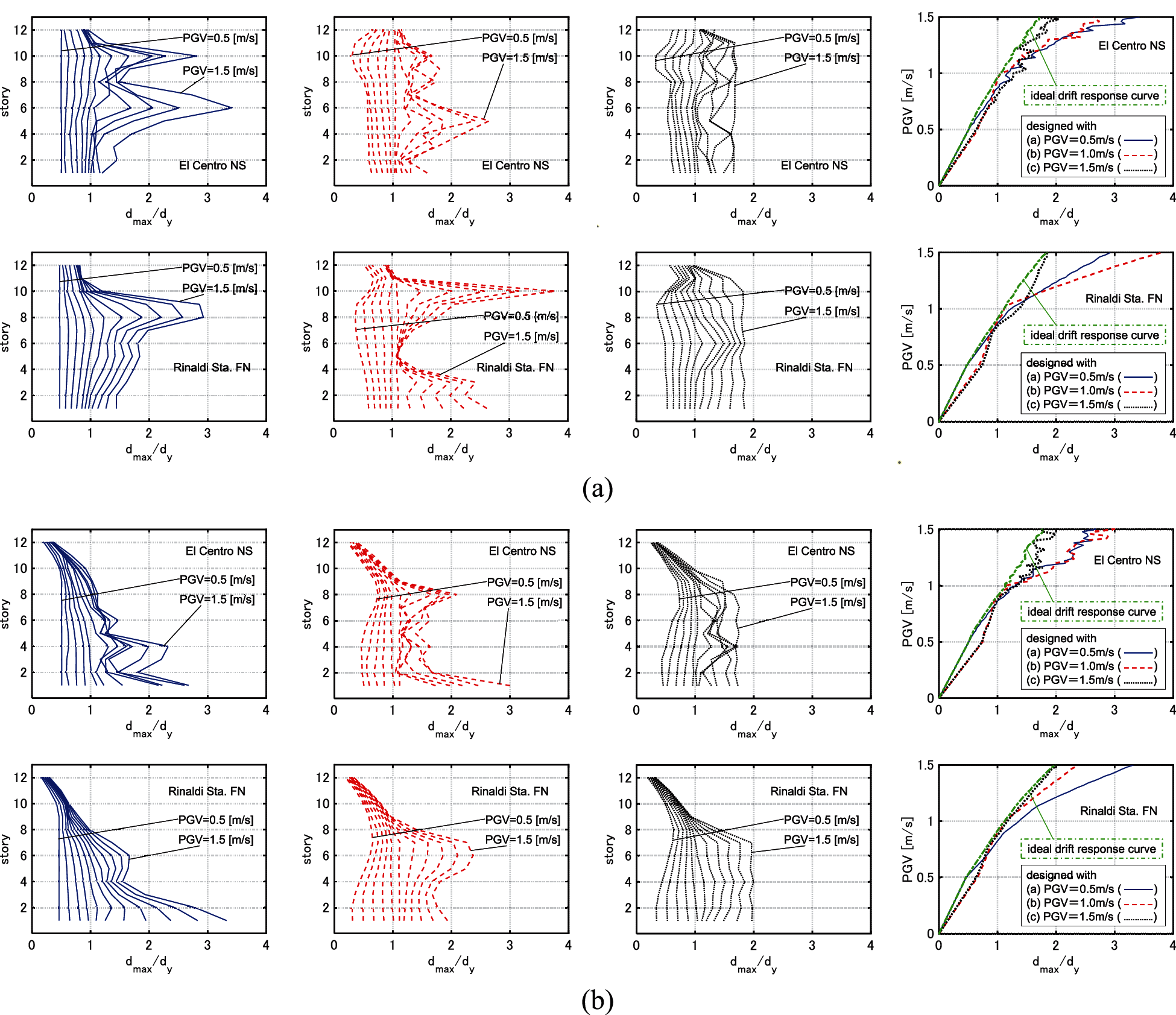
Figure 15: IDA analysis for 3 models designed under GMs with PGV = 0.5, 1.0, 1.5 [m/s] (
4 Problem of Robust Optimal Damper Placement for Multi-Level Ground Motions
This section treats a robust optimal design problem, and a simple local search-based algorithm is proposed. A simple index using the IDRC and the IDA curve of the model is used as the objective function.
4.1 Optimization Problem and Its Solution Algorithm
Consider the following problem to mathematically obtain damper designs whose IDA curves run near the IDRCs.
[Problem of Robust Optimal Damper Placement for Multi-Level GMs (PRODPMG)]
Find
so as to minimize
subject to
The objective function represents the maximum value of the horizontal distances between the IDRC with W = Wc and the IDA curve of the design with at every IM in the IM-
The solution algorithm for the problem PRODPMG may be described as follows:
[Algorithm]
Step 1 Obtain the IDRC by A-CDGM. Set
Step 2 Set
Step 3 Find the level of the GMs IMi where the value of
Step 4 Find the story j that exhibits the largest value of the interstory drift under the GMs IM = IMi.
Step 5 Find the story
Step 6 Update
The procedures of Steps 4–6 in the algorithm is common with the proposed local search method in Section 2.3.
The targeted value of the sum of the added damping coefficients are set to
Fig. 16 shows the results of the optimization. The IDA curve of the obtained design runs quite near the IDRC for various PGVs. Moreover, the distributions of the interstory drifts are uniformized for various PGVs.
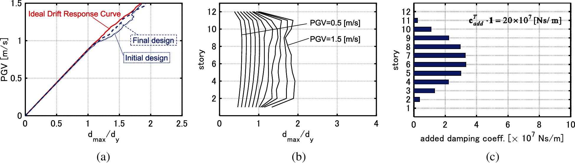
Figure 16: Results of optimization (
It may be concluded that the proposed algorithm provides robust damper designs for various levels of GMs. The proposed algorithm works well in spite of simplicity.
A new method of robust damper design was presented for elastic-plastic MDOF building structures under multi-level ground motions (GMs). The main conclusions can be summarized as follows.
(1) An ideal drift response curve (IDRC) is a plot of the optimized maximum deformation under a constraint on the total damper quantity versus the design IM (level of input GMs). An effectiveness of the design for various levels of GMs can be captured visually through plotting the incremental dynamic analysis (IDA) curve and the corresponding IDRC.
(2) A problem of generation of IDRCs was stated and the solution algorithm ‘advanced consecutive design generation method (A-CDGM)’ was developed. A-CDGM consists of the sensitivity-based algorithm and a local search method. The combination of these two algorithms enables the comprehensive search of the optimal solutions for various conditions of the level of the GMs and the sum of the added damping coefficient.
(3) The slope of IDRCs of viscous dampers under pulse type GMs inclines towards the horizontal direction in the upper range of IM. This is because viscous dampers are not necessarily effective for pulse type GMs. On the other hand, the values of the maximum interstory drifts under pulse type GMs are greatly improved as the sum of the added stiffnesses of hysteretic dampers increases. This is because hysteretic dampers are more effective for pulse type GMs than viscous dampers. In the case of GMs of random nature, both types of dampers effectively reduce the maximum interstory drifts.
(4) In the case of optimization of viscous dampers, as IM used for the optimization becomes larger, the dampers concentrated to the specified stories spread around those stories to prevent the plastic deformation concentrations at the surrounding stories without dampers for larger levels of GMs. Moreover, as IM used for the optimization becomes larger, the amplitudes of the transfer functions become small in the higher range of frequency.
(5) In the case of optimization of hysteretic dampers, the added stiffness is allocated to the stories which exhibit the large deformations as IM used for the optimization becomes larger. The dissipated hysteretic energy of dampers is small under the lower levels of the GMs. Therefore, the control of the distribution of stiffness mainly contributes to the uniformization of the distribution of the maximum interstory drifts under the lower levels of GMs. On the other hand, both the hysteretic energy dissipation of the dampers and the control of the distribution of stiffness play an important role for the uniformization under the larger levels of GMs.
(6) For both types of dampers, the IDA curves for the models designed under larger levels of GMs run near the corresponding IDRCs for various IMs. On the other hand, the IDA curves for the models designed under lower levels of GMs are away from the IDRCs in the upper range of IM. In other words, such designs may exhibit large plastic deformation concentrations in specific stories for larger-level GMs.
(7) A robust optimal design problem was formulated and a simple local search-based algorithm was proposed. A simple index using an IDRC and an IDA curve was used as the objective function. This method realizes a design which is effective for various levels of GMs and this means the robust optimal design. Moreover, the proposed algorithm is easy to use because of its simplicity.
In this paper, a single type of dampers was applied to the optimization. It is noted that the proposed method is applicable to the simultaneous optimization of various types of dampers. It is also noted that the proposed method is suitable for optimization under plural GMs. In such case, the envelope response under such plural GMs should be treated as the objective function.
Funding Statement: Part of the present work is supported by the Grant-in-Aid for Scientific Research (KAKENHI) of the Japan Society for the Promotion of Science (Nos. 18H01584, JP20J20811). This support is greatly appreciated.
Conflicts of Interest: The authors declare that they have no conflicts of interest to report regarding the present study.
1. Takewaki, I., Ben-Haim, Y. (2005). Info-gap robust design with load and model uncertainties. Journal of Sound and Vibration, 288(3), 551–570. DOI 10.1016/j.jsv.2005.07.005. [Google Scholar] [CrossRef]
2. Kanno, Y., Takewaki, I. (2006). Sequential semidefinite program for maximum robustness design of structures under load uncertainty. Journal of Optimization Theory and Applications, 130(2), 265. DOI 10.1007/s10957-006-9102-z. [Google Scholar] [CrossRef]
3. Mathakari, S., Gardoni, P., Agarwal, P., Raich, A., Haukaas, T. (2007). Reliability-based optimal design of electrical transmission towers using multi-objective genetic algorithms. Computer-Aided Civil and Infrastructure Engineering, 22(4), 282–292. DOI 10.1111/j.1467-8667.2007.00485.x. [Google Scholar] [CrossRef]
4. Marano, G. C., Sgobba, S., Greco, R., Mezzina, M. (2008). Robust optimum design of tuned mass dampers devices in random vibrations mitigation. Journal of Sound and Vibration, 313(3–5), 472–492. DOI 10.1016/j.jsv.2007.12.020. [Google Scholar] [CrossRef]
5. Fujita, K., Takewaki, I. (2011). An efficient methodology for robustness evaluation by advanced interval analysis using updated second-order taylor series expansion. Engineering Structures, 33(12), 3299–3310. DOI 10.1016/j.engstruct.2011.08.029. [Google Scholar] [CrossRef]
6. Lavan, O., Avishur, M. (2013). Seismic behavior of viscously damped yielding frames under structural and damping uncertainties. Bulletin of Earthquake Engineering, 11(6), 2309–2332. DOI 10.1007/s10518-013-9479-7. [Google Scholar] [CrossRef]
7. Scozzese, F., Dall’Asta, A., Tubaldi, E. (2019). Seismic risk sensitivity of structures equipped with anti-seismic devices with uncertain properties. Structural Safety, 77, 30–47. DOI 10.1016/j.strusafe.2018.10.003. [Google Scholar] [CrossRef]
8. Vamvatsikos, D., Cornell, C. A. (2001). Incremental dynamic analysis. Earthquake Engineering & Structural Dynamics, 31(3), 491–514. DOI 10.1002/(ISSN)1096-9845. [Google Scholar] [CrossRef]
9. Takewaki, I. (2009). Building control with passive dampers: Optimal performance-based design for earthquakes. Asia, Singapore: John Wiley & Sons. [Google Scholar]
10. de Domenico, D., Ricciardi, G., Takewaki, I. (2019). Design strategies of viscous dampers for seismic protection of building structures: A review. Soil Dynamics and Earthquake Engineering, 118, 144–165. DOI 10.1016/j.soildyn.2018.12.024. [Google Scholar] [CrossRef]
11. Takewaki, I., Akehashi, H. (2021). Comprehensive review of optimal and smart design of nonlinear building structures with and without passive dampers subjected to earthquake loading. Frontiers in Built Environment, 7, 631114. DOI 10.3389/fbuil.2021.631114. [Google Scholar] [CrossRef]
12. Zhang, R. H., Soong, T. T. (1992). Seismic design of viscoelastic dampers for structural applications. Journal of Structural Engineering, 118(5), 1375–1392. DOI 10.1061/(ASCE)0733-9445(1992)118:5(1375). [Google Scholar] [CrossRef]
13. Garcia, D. L. (2001). A simple method for the design of optimal damper configurations in MDOF structures. Earthquake Spectra, 17, 387–398. DOI 10.1193/1.1586180. [Google Scholar] [CrossRef]
14. Takewaki, I. (1997). Optimal damper placement for minimum transfer functions. Earthquake Engineering & Structural Dynamics, 26(11), 1113–1124. DOI 10.1002/(ISSN)1096-9845. [Google Scholar] [CrossRef]
15. Aydin, E., Boduroglub, M. H., Guney, D. (2007). Optimal damper distribution for seismic rehabilitation of planar building structures. Engineering Structures, 29, 176–185. DOI 10.1016/j.engstruct.2006.04.016. [Google Scholar] [CrossRef]
16. Trombetti, T., Silvestri, S. (2004). Added viscous dampers in shear-type structures: The effectiveness of mass proportional damping. Journal of Earthquake Engineering, 8(2), 275–313. DOI 10.1080/13632460409350490. [Google Scholar] [CrossRef]
17. Whittle, J. K., Williams, M. S., Karavasilis, T. L., Blakeborough, A. (2012). A comparison of viscous damper placement methods for improving seismic building design. Journal of Earthquake Engineering, 16(4), 540–560. DOI 10.1080/13632469.2011.653864. [Google Scholar] [CrossRef]
18. Martínez, C. A., Curadelli, O., Compagnoni, M. E. (2014). Optimal placement of nonlinear hysteretic dampers on planar structures under seismic excitation. Engineering Structures, 65, 89–98. DOI 10.1016/j.engstruct.2014.01.030. [Google Scholar] [CrossRef]
19. Aydin, E., Ozturk, B., Bogdanovic, A., Farsangi, E. N. (2020). Influence of soil-structure interaction (SSI) on optimal design of passive damping devices. Structures, 28, 847–862. DOI 10.1016/j.istruc.2020.09.028. [Google Scholar] [CrossRef]
20. Singh, M. P., Moreschi, L. M. (2002). Optimal placement of dampers for passive response control. Earthquake Engineering & Structural Dynamics, 31(4), 955–976. DOI 10.1002/(ISSN)1096-9845. [Google Scholar] [CrossRef]
21. Dargush, G. F., Sant, R. S. (2005). Evolutionary aseismic design and retrofit of structures with passive energy dissipation. Earthquake Engineering & Structural Dynamics, 34(13), 1601–1626. DOI 10.1002/eqe.497. [Google Scholar] [CrossRef]
22. Apostolakis, G. (2020). Optimal evolutionary seismic design of three-dimensional multistory structures with damping devices. Journal of Structural Engineering, 146(10), 4020205. DOI http://dx.doi.org/10.1061/(ASCE)ST.1943-541X.0002775. [Google Scholar]
23. Akehashi, H., Takewaki, I. (2021a). Modeling of resilience based on categorized recovery scenario and improving resilience with viscous damper. Journal of Structural and Construction Engineering, 86(782), 577–588 (in Japanese). DOI 10.3130/aijs.86.577. [Google Scholar] [CrossRef]
24. Castaldo, P., de Iuliis, M. (2014). Optimal integrated seismic design of structural and viscoelastic bracing-damper systems. Earthquake Engineering & Structural Dynamics, 43(12), 1809–1827. DOI 10.1002/eqe.2425. [Google Scholar] [CrossRef]
25. Akehashi, H., Takewaki, I. (2020b). Simultaneous optimization of elastic-plastic building structures and viscous dampers under critical double impulse. Frontiers in Built Environment, 6, 211. DOI 10.3389/fbuil.2020.623832. [Google Scholar] [CrossRef]
26. Balling, R. J., Bhatti, M. A., Ciampi, V., Pister, K. S. (1981). Interactive optimal design of dynamically loaded structures using the OPTNSR software system. Proceedings of the International Symposium on Optimum Structural Design, pp. 12.9–12.17. Arizona. [Google Scholar]
27. Bhatti, M. A., Ciampi, V., Pister, K. S., Polak, E. (1981). An interactive software system for optimal design of statically and dynamically loaded structures with nonlinear response. Proceedings of the International Symposium on Optimum Structural Design, pp. 12–19. Arizona. [Google Scholar]
28. Attard, T. L. (2007). Controlling all interstory displacements in highly nonlinear steel buildings using optimal viscous damping. Journal of Structural Engineering, 133(9), 1331–1340. DOI 10.1061/(ASCE)0733-9445(2007)133:9(1331). [Google Scholar] [CrossRef]
29. Akehashi, H., Takewaki, I. (2019). Optimal viscous damper placement for elastic-plastic MDOF structures under critical double impulse. Frontiers in Built Environment, 5, 20. DOI 10.3389/fbuil.2019.00020. [Google Scholar] [CrossRef]
30. Idels, O., Lavan, O. (2021). Optimization based seismic design of steel moment resisting frames with nonlinear viscous dampers. Structural Control and Health Monitoring, 28(1), e2655. DOI 10.1002/stc.2655. [Google Scholar] [CrossRef]
31. Akehashi, H., Takewaki, I. (2020a). Comparative investigation on optimal viscous damper placement for elastic-plastic MDOF structures: Transfer function amplitude or double impulse. Soil Dynamics and Earthquake Engineering, 130, 105987. DOI 10.1016/j.soildyn.2019.105987. [Google Scholar] [CrossRef]
32. Akehashi, H., Takewaki, I. (2021b). Efficient damper design method for elastic-plastic MDOF structures under consecutive-level earthquakes. 8th ECCOMAS Thematic Conference on Computational Methods in Structural Dynamics and Earthquake Engineering, National Technical University of Athens (NTUA). [Google Scholar]
33. Murakami, Y., Noshi, K., Fujita, K., Tsuji, M., Takewaki, I. (2013). Simultaneous optimal damper placement using oil, hysteretic and inertial mass dampers. Earthquakes and Structures, 5(3), 261–276. DOI 10.12989/eas.2013.5.3.261. [Google Scholar] [CrossRef]
34. Xu, Z., Agrawal, A. K., He, W. L., Tan, P. (2007). Performance of passive energy dissipation systems during near-field ground motion type pulses. Engineering Structures, 29(2), 224–236. DOI 10.1016/j.engstruct.2006.04.020. [Google Scholar] [CrossRef]
 | This is an open access article distributed under the terms of the Creative Commons Attribution License, which permits unrestricted use, distribution, reproduction and adaptation in any medium and for any purpose provided that it is properly attributed. For attribution, the original author(s), title, publication source (PeerJ) and either DOI or URL of the article must be cited. |