| Computer Modeling in Engineering & Sciences |
DOI: 10.32604/cmes.2021.014852
ARTICLE
Multi-Floor Indoor Trajectory Reconstruction Using Mobile Devices
1College of Computing and Informatics, Saudi Electronic University, Riyadh, 11673, Saudi Arabia
2School of Computing, Telkom University, Bandung, 40257, Indonesia
3Computer Science and Information Technology, La Trobe University, Melbourne, 3086, Australia
*Corresponding Author: Sultan Alamri. Email: salamri@seu.edu.sa
Received: 4 November 2020; Accepted: 18 March 2021
Abstract: An indoor trajectory is the path of an object moving through corridors and stairs inside a building. There are various types of technologies that can be used to reconstruct the path of a moving object and detect its position. GPS has been used for reconstruction in outdoor environments, but for indoor environments, mobile devices with embedded sensors are used. An accelerometer sensor and a magnetometer sensor are used to detect human movement and reconstruct the trajectory on a single floor. In an indoor environment, there are many activities that will create the trajectory similar to an outdoor environment, such as passing along the corridor, going from one room to another, and other activities. We need to analyse trajectories to obtain the movement patterns, understand the most frequently visited places or paths used as well as the least frequented ones. Furthermore, we can utilize movement patterns to obtain a better building design and layout. The latest studies focus on reconstructing the trajectory on a single floor. However, actual indoor environments are comprised of multi-floors and multi-buildings. The purpose of this paper is to reconstruct a trajectory in an indoor multi-floor environment. We have conducted extensive experiments to evaluate the performance of our proposed algorithms in a campus building. The result of our experiment shows that the height of the building can be detected using a barometer sensor that gives an atmospheric pressure reading which is then transformed by setting the range value according to the number of floors, enabling the sensors to detect activity in a multi-floor building. The readings obtained from the magnetometer sensor can be used to reconstruct the trajectory similar to the real path based on the direction and degree of direction. The system accuracy in recognizing steps in a multi-floor building is about 84%.
Keywords: Reconstruction; indoor trajectory; multi-floor; accelerometer; barometer; magnetometer
Tracking is a process used for observing objects on the move over a period of time [1–3]. One example of the tracking process is when we are using Google Maps to navigate from one point to a destination point, then the system will start to observe the movement of the vehicle or footstep in real time [4]. The tracking process gives a timely, ordered sequence of location data for further processing. The tracking data is utilized by Google to develop the path history using the timeline feature which the called trajectory [5]. Fig. 1a shows the navigation feature on Google Maps, that can be used to guide or help the user to find his/her destination. Fig. 1b shows the timeline Feature on Google Maps.
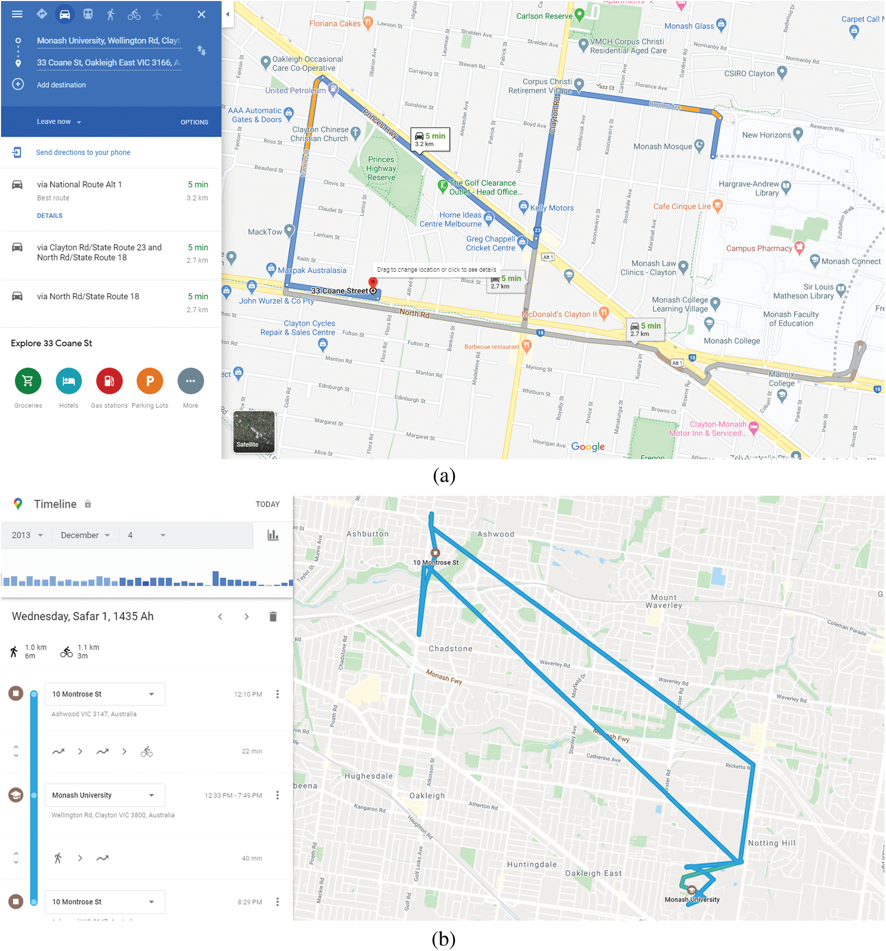
Figure 1: Google maps navigation (a) Google maps navigation using GPS (b) Timeline feature on Google maps
A trajectory is the path that a moving object follows through space as a function of time [6]. A trajectory can be formed in an outdoor or indoor environment. Many people use Google Maps to help them find a place, guide them to their destination, or for other reasons. Hence, when we are using Google maps, we should turn on the GPS of the mobile device [7,8]. Knowing a trajectory can benefit both Google maps and its users. Users can track their movement history; and Google can use the history of users? trajectories to recommend the fastest routes to their destinations because the data is time-ordered and also indicates the places most often visited by the users [9,10].
Nowadays, many people spend a great deal of time in indoor spaces such as homes, office buildings, campuses, shopping centers, stations, airports or other buildings [2]. In indoor environments, people engage in a number of walking activities such as passing along a corridor, moving from one room to another or gathering somewhere [3,11]. These activities will create a trajectory pattern. Therefore, there is some similarity between an outdoor environment and an indoor environment. However, indoor environments may consist of dozens of floors, such as skyscrapers [11], they may also consist of multi-buildings in structures known as “inter-building” [12]. GPS performance in indoor environments has poor accuracy compared to its performance outdoors. The accuracy is approximately 5 m outdoors, 7 m in forested areas and 10m in enclosed environments [11,13]. It is even less in a concrete building, making it highly unsuitable for indoor environments. While 5 m misplacement for outdoor environment might not give significant issues, In an indoor environment, 1 m misplacement might put the user in an incorrect room or outside the building. Another thing that needs to be considered is the dynamic obstacles such as furniture that moves frequently. It means the trajectory path from one place to another might be different from time to time.
In an indoor environment, there are several factors that can affect GPS accuracy, so it is difficult to track the movements of people inside a building or beneath a roof or canopied structure [11,13]. Furthermore, with the recent technologies such as RFID, Bluetooth and WI-FI which are used in positioning devices in indoor spaces, many of the developing countries, users or institutions cannot afford to have additional devices to support indoor localisation infrastructures. Therefore, one effective way to detect more accurately the movement of a person or object indoors is by means of a mobile device. Mobile devices are suitable for indoor environments because: (1) many embedded sensors are available; [3,14]. (2) mobile phones are ubiquitous, simple to use, and relatively inexpensive; (3) many people appear to be attached to their phones [14,15]. Thus, a sensor embedded in the mobile device can offer an alternative to the traditional GPS technology. Knowing a trajectory in indoor environments has several benefits. For example, in a crowded shopping center, a customer can follow his trajectory to determine where he might have left his wallet. The trajectory data on the mobile device can be used to know the path to visited places and then the path is used to re-record the incident before the wallet was forgotten.
Reference [11] has reconstructed the trajectory in an indoor environment. The focus is on the single floor and the accelerometer and magnetometer sensors are utilised. While in the real live, indoor environment is consist of multi-floor even multi-building called inter-building. The aim of this paper is to reconstruct the trajectory in a multi-floor indoor environment by means of a barometer sensor embedded in the mobile device. The indoor environment that will be used to implement the trajectory reconstruction is the Kultubai Selatan (F) multi-floor building at Telkom University. For the purpose of trajectory reconstruction, sensors embedded in the mobile device will be utilized. These sensors are: the accelerometer sensor to measure acceleration force to detect the motion of the device, a magnetometer sensor bearing, and a barometer sensor to calculate the ambient air pressure. It is anticipated that the ambient air pressure reading can be transformed into the number of floor of the building.
This paper is organized as follows: Section 2 presents the relevant background. Section 3 describes the Multi-Floor Indoor Trajectory Reconstruction, materials and methods. Section 4 presents the results of the experiment and their evaluation. Section 5 concludes the paper and states proposed future work.
This section presents a review of the literature pertaining to the tracking of movement indoors, with a focus on: 1) trajectory tracking, 2) android sensor devices; and 3) algorithms.
Tracking is used for observing objects on the move over time in either an indoor or outdoor environment [1,3]. This can be in indoor environment or outdoor environment. One application that uses GPS for tracking in outdoor positioning is the Time line Feature on Google Maps [7,8]. However, in an indoor environment, GPS is not easily applicable for tracking as it is in an outdoor environment [16,17].
Many technologies are used in positioning devices in indoor environments, such as RFID, Bluetooth and WI-FI. Also, other recent technologies that can be implemented in an indoor environment include Receive Signal Strength (RSSI) and compressive sensing [3,16,18], RSSI and MEMS sensor [19], and Android and WLAN [16,20].
Two methods can be used to track objects in 3-D space, namely Outside-In tracking and Inside-Out tracking. Outside-In tracking is a method that requires another object such as a beacon, tower or camera, while Inside-Out tracking does not require any external sensors or beacons [21]. Instead, the object being tracked has one or more cameras and an inertial measurement unit (magnetometer, gyroscope and accelerometer) on it which observe the environment and senses it [8,22].
Because the outdoor environment is spacious, GPS technology can be used to form the trajectory. People conduct a range of activities outdoors, all of which will create the trajectory pattern. The trajectory will be used for tracking using an environmental magnetic field [23], to define trajectory queries, and for trajectory indexing [6]. Furthermore, some works have used the integration of hardware and software, which brings a simple and natural platform with a WMR prototype. These systems aim to achieve the wireless planning, generation, and tracking of trajectories using the WMR and augmented reality [24,25]. Also, many works have focused on trajectory planning algorithms and mobility for robots in order to avoid obstacles in indoors spaces. For instance, an online trajectory planning algorithm based on state-time and the partial trajectory adjustment algorithm enabled the robot to achieve an optimal collision avoidance performance in high dense dynamic environments [26]. Moreover, a novel approach has been proposed in order to efficiently produce crash-free optimal trajectories for multiple moving robots in obstacle-rich indoor environments [27].
However, the accuracy of indoor positioning systems is influenced locally by static elements such as the architecture of a building. Hence, positioning in or around buildings often has static local biases, distorting the positioning estimate in a specific direction [4,9]. Not much different from an outdoor environment, in an indoor environment, people engage in a range of activities such as moving from room to another, passing along a corridor, or gathering somewhere. All these activities will create a trajectory pattern [11]. Because of the nature of the interior of buildings, space in indoor environments is limited by a number of factors such as walls, doors and stairways [10,11]. These limitations can block signals to the the GPS device. Moreover, other technologies such as RFID, Bluetooth and WI-FI might be not available in all institutions buildings infrastructures, due to the high costs. However, these problems can be resolved by embedding sensors in a mobile device, enabling the construction of a trajectory pattern in an indoor environment which will be explained next.
Nowadays, most people use a mobile device. Mobile phones are ubiquitous, ease of use, and relatively inexpensive [5,14]. Moreover, people tend to have attachments to their phone [14,15,28]. There are many advantages of using a mobile device as a sensor device for tracking:
1. The requisite sensors are built in. As long as the desired context can be derived and recognized from the data obtained by the embedded sensors, the users do not need to use external sensors in order to obtain required information [4,14].
2. The smartphones of today have many features that enable context-aware related implementations. Most smartphones have relatively high processing power and sufficient memory for data processing tasks [14]. The smartphone itself is a small computing device with integrated common connectivity.
3. Most smartphones have also relatively long operation durations. For an average user, under normal usage patterns, a smartphone should have at least a day operation time before a recharge is required [29,30].
3 Multi-Floor Indoor Trajectory Reconstruction
3.1 Embedded Sensors on the Mobile Device
Sensors are devices that can detect specific events and can measure motion, orientation, and various environmental conditions. These sensors are capable of providing raw data with high precision and accuracy, and are useful for monitoring the movement or positioning of three-dimensional devices, or changes in the ambient environment near a device. For example, a travel application might use the geomagnetic field sensor and accelerometer to report a compass bearing. The Android platform supports three broad categories of sensors [21,30]: motion sensors, environment sensors, position sensors.
The sensors’ framework on Android uses a standard three-axis coordinate system to obtain data readings [21,30]. For most sensors, the coordinate system is defined relative to the device’s screen when the device is held in its default orientation.
When a device is held in its default orientation, the X axis is horizontal and points to the right, the Y axis is vertical and points upward, and the Z axis points toward the outside of the screen face. In this system, coordinates behind the screen have negative Z values.
Two important points to remember are: in this coordinate system, the axes are not swapped when the device’s screen orientation changes; and the sensor coordinate system is always based on the natural orientation of a device [11].
There are various types of sensors such as accelerometer sensors, gravity sensors, gyroscopes, and rotational vector sensors [21,31]. However, this experiment focuses only an accelerometer sensor. Motion sensors are used to measure the acceleration force and rotational force along three axes. Motion sensors are useful for monitoring device movement or detecting device motion.
An accelerometer measures the acceleration force in m/s2 that is applied to a device on all its physical axes (x, y, and z), including the force of gravity. This sensor is generally used for the detection of motions such as shaking, tilting, rotating or swinging. An accelerometer is available on API level 14, level 9, level 8 and level 3. An accelerometer sensor looks like a gravity sensor, apart from one difference. Accelerometers measure the acceleration force and the force of gravity [21,30]. Hence, when the device is sitting on a table (and obviously not accelerating), the accelerometer’s reading shows a magnitude of
For example, when the device lies flat on a table and is pushed on its left side toward the right, the x acceleration value is positive (Fig. 2).
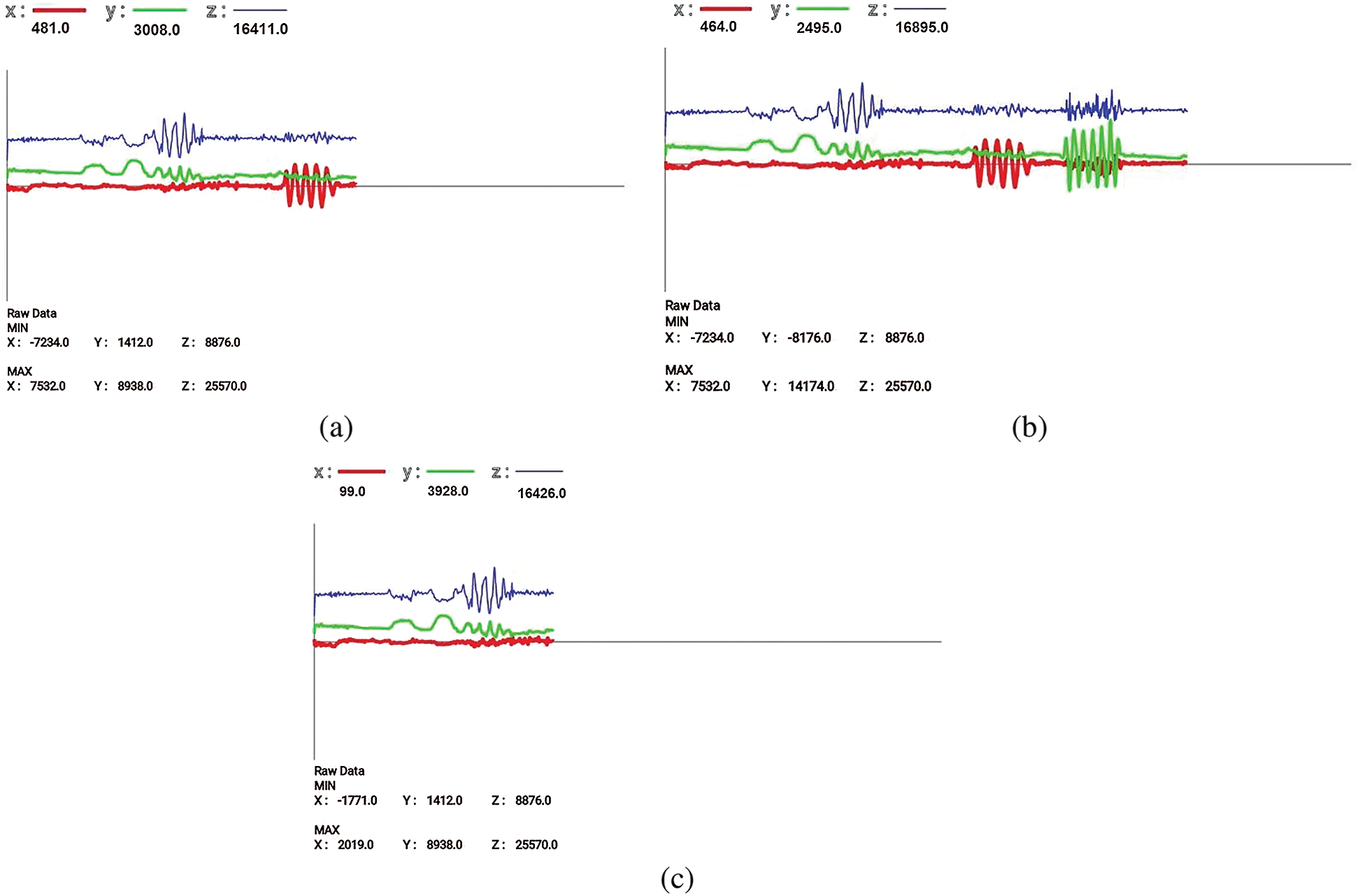
Figure 2: Graph of accelerometer reading. (a) Device is pushed on its left side toward the right (b) Device is pushed on its up side toward the down (c) Device is pushed on its front side toward the back
Environment sensors are used to measure or monitor various environmental parameters. Some sensors can be used to monitor relative ambient humidity, ambient pressure, and ambient temperature. Barometers, photometers, and thermometers come under this category of sensors [21,32]. The focus of this paper is only on pressure sensors.
The pressure was calculated as
Nowadays, a modern smartphone can be embedded with a barometer to increase GPS results in regard to elevation, because the device can be affected by atmospheric pressure [32]. Data measured by sensors is then used to determine how high the device is above sea level, which in turn results increases the GPS accuracy. In terms of barometric measurement, 1000 hPa is equal to 1000 mbar, which is equal to 750 mm of mercury in a barometric column, which is 0.987 of the average atmospheric pressure, which on global average is 1013 millibars or hectopascals [32,33].
In this study, we transform the result of the pressure sensor reading to detect the number of floors in the building by setting the range value.
Position sensors are used to measure the physical position of a device. Orientation sensors and magnetometers come under this category of sensors [21,34]. This experiment demonstrates the function of a magnetometer. A magnetometer measures the ambient geomagnetic field in the X, Y, and Z axis in
The architecture of the proposed system consists of a mobile application to record the sensor value, and a computer program to develop the path or to reconstruct the trajectory. A detailed explanation of each component of the architecture will be given below. Fig. 3 illustrates the system architecture and its flow.
In the first stages, the mobile device applications include the embedded sensors: accelerometer, magnetometer and barometer sensors. When we click the start button on the smartphone or mobile device, it will record the sensor readings. The accelerometer sensor will detect the acceleration of the gravitational force on the x, y, and z axes when the application is running. The magnetometer sensor is used to serve as a compass that shows the direction and angle formed by mobile devices against the compass point, while the barometer sensor is used to detect or calculate the height according to the range that has been defined.
The data obtained from the sensors that will be recorded on Google Firebase comprise bearings, the number of steps and the barometer reading. The data is recorded as soon as a footstep is detected. In the second stage, the computer program is used to process the data and reconstruct the data as a path. To reconstruct the path, we have to know the value of coordinates. This value is obtained from the calculation of angles using trigonometric rules.
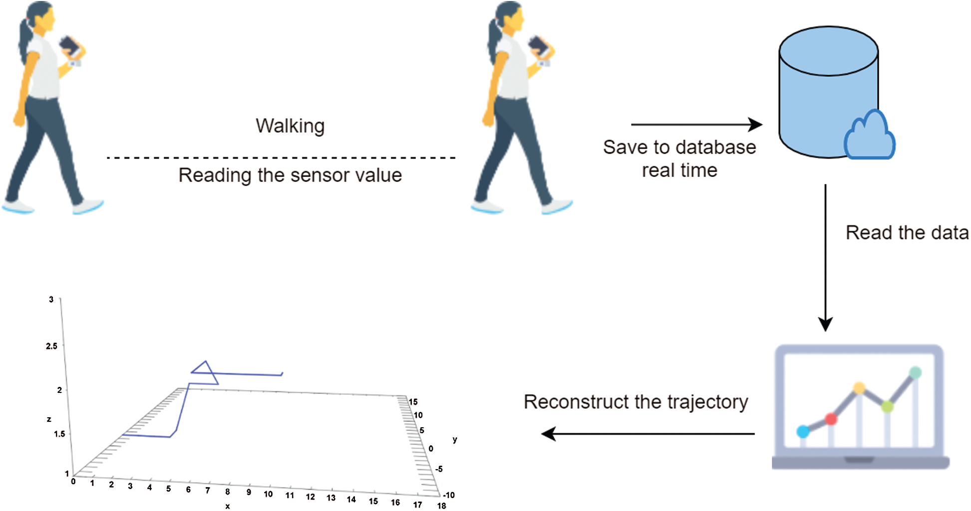
Figure 3: Overview of system architecture
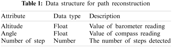
To reconstruct an indoor trajectory, we need sensors embedded in a smartphone, so we will need a feature that can save sensor readings. The data structure will be stored in this system as shown in Tab. 1. The barometer sensor reading is saved as an altitude attribute. The angle is seen in the compass reading obtained from the magnetometer sensor. By knowing the angle, we can make a line to reconstruct the trajectory. The last one is the number of steps. This attribute will save the number of steps when movement is detected by the smartphone.
The first algorithm as shown in Algorithm 1 is used to record accelerometer and magnetometer sensor values. Accelerometer sensor is used as pedometer (electronic device used to count the steps of people walking), magnetometer is used as a compass to record the directions and the degree value of the direction. The use of Signal Vector Magnitude (SVM) is proposed to detect walking condition or stop [11]. Walking is a condition where there is a movement position of the object from one point to another point while stopping is a condition where there is no movement position from one point to another point. Below is calculation of SVM (1).
The first algorithm is used to record accelerometer and magnetometer sensor readings. The accelerometer sensor is used as a pedometer (an electronic device used to count the steps of people walking); the magnetometer is used as a compass to record the directions and the angle of the direction. The use of a Signal Vector Magnitude (SVM) is proposed to detect walking or stopping [11]. Walking is a condition where the object takes steps to move from one point to another; stopping is a condition where the object does not move from one point to another point. Below is the calculation of SVM (1).
The SVM calculates the acceleration value when walking [11]. The Accx, Accy, and Accz are the values based on the physical of x, y, and z axes of accelerometer sensor reading.
The second algorithm is proposed for the reconstruction of the trajectory (Algorithm 2). First, the data is preprocessed. The data that will be used is the size of the angle and the number of steps recorded. The data is labelled as 1 if a step is detected, and labelled as 0 if it stops [11].
A trigonometric theorem as shown in Tab. 2 is used for the reconstruction. The Trigonometry Theorem is used to obtain the value of coordinates in a Cartesian diagram. Since we have the value of the angle from the compass reading that shows the angle and direction for human movement. Below is the basic formula for the trigonometry theorem:

In algorithm two has been implemented trigonometric theorem, the result of reconstruction does not match the actual path [11], so a trial and error step is proposed. Based on trial and error, Reference [11] found the formula that establishes the real path. Also, Since the Cartesian diagram that will be used is in quadrant 1, the development of trigonometric formulas is carried out according to the formula for quadrant 1 below:
The next algorithm shows how to record the value of the sensors and detect the footsteps saved on the database. In this algorithm, the accelerometer sensor is used to detect and recognize the number of steps (footstep), the compass bearings found by the magnetometer sensor, and the altitude readings obtained by the barometer sensor. First, to detect whether an activity is a walking or stopping one, we do a SVM (Signal Vector Magnitude) calculation and then normalize the SVM result. The result of this normalization is used to calculate the velocity of the human movement, so that we can recognize the activities (walk or stop). After the system recognizes or detects the number of steps, the data of angles, number of steps, and altitudes is stored in the Firebase database.
In the algorithm used for reconstructing trajectories, the system will read all data stored in the database. Based on the previous explanation, the data to be read is the direction, size of the angle, number of steps, and altitude. Data stored in the database certainly shows human movement activity which is a running activity, so there must be a number of steps to be detected.
In this section, we will describe the testing scenario, and present the results of the experiment. The results will indicate the level of accuracy of the system in terms of recognizing the steps. In this evaluation, we use Android devices as since Android dominates worldwide market share, especially in developing countries.
We built a testing area replicating a Cartesian diagram consisting of three axes where the x-axis represents the east direction of the wind, the y-axis represents the north direction of the wind, and the z-axis represents the value of the barometer reading which will be turned into a floor. The numbers on the x, y, and z-axes represent every 1 footstep, which is set for a woman with an average height of 153 cm and a footstep length of about 38 cm. The path testing scenario is divided into a single floor and a multi-floor. The single floor is depicted in Figs. 4 and 5 shows the multi floor.
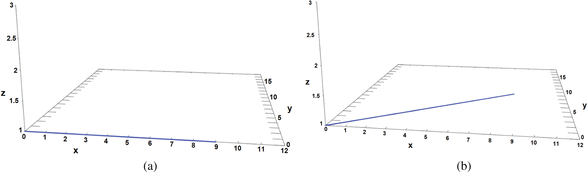
Figure 4: Illustration of tow different paths on single floor. (a) Walking direction to the east (b) Walking direction to the diagonal
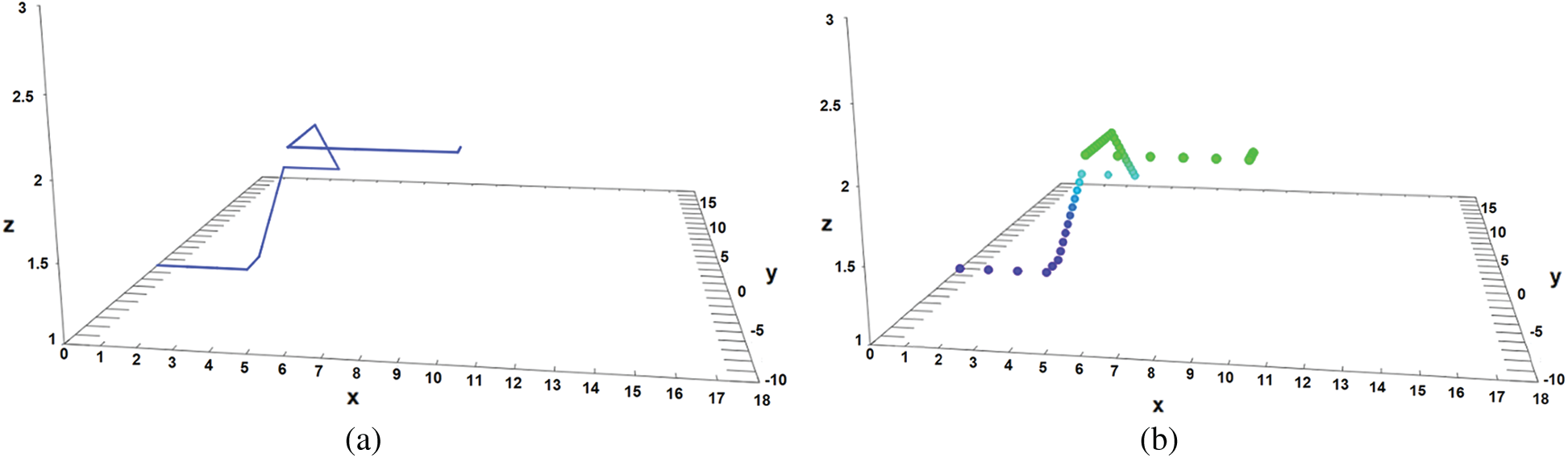
Figure 5: Illustration of path on multi-floor. (a) The walking direction from the first floor to the second floor (b) The number of footsteps detected
For the test scenario, the effect of threshold and device position will be taken into account. The threshold is used because pedometer applications commonly apply it to recognize human steps. In this experiment, only walking and stopping activities are considered. The other factor is the placement of the device, which also impacts on threshold and step detection.
When the mobile device is utilized as a compass, we hold the device at an angle of 0
We proposed various threshold values to recognize walking or stopping activity, ranging from from 0.1 to 0.5. The threshold value affects the recognition of steps (walking activity) because the step will recognize whether the SVM calculation exceeds the threshold value. The smaller the threshold value, the more sensitive the system is to recognizing the step. Fig. 6 shows the accelerometer reading the human movements are detected.
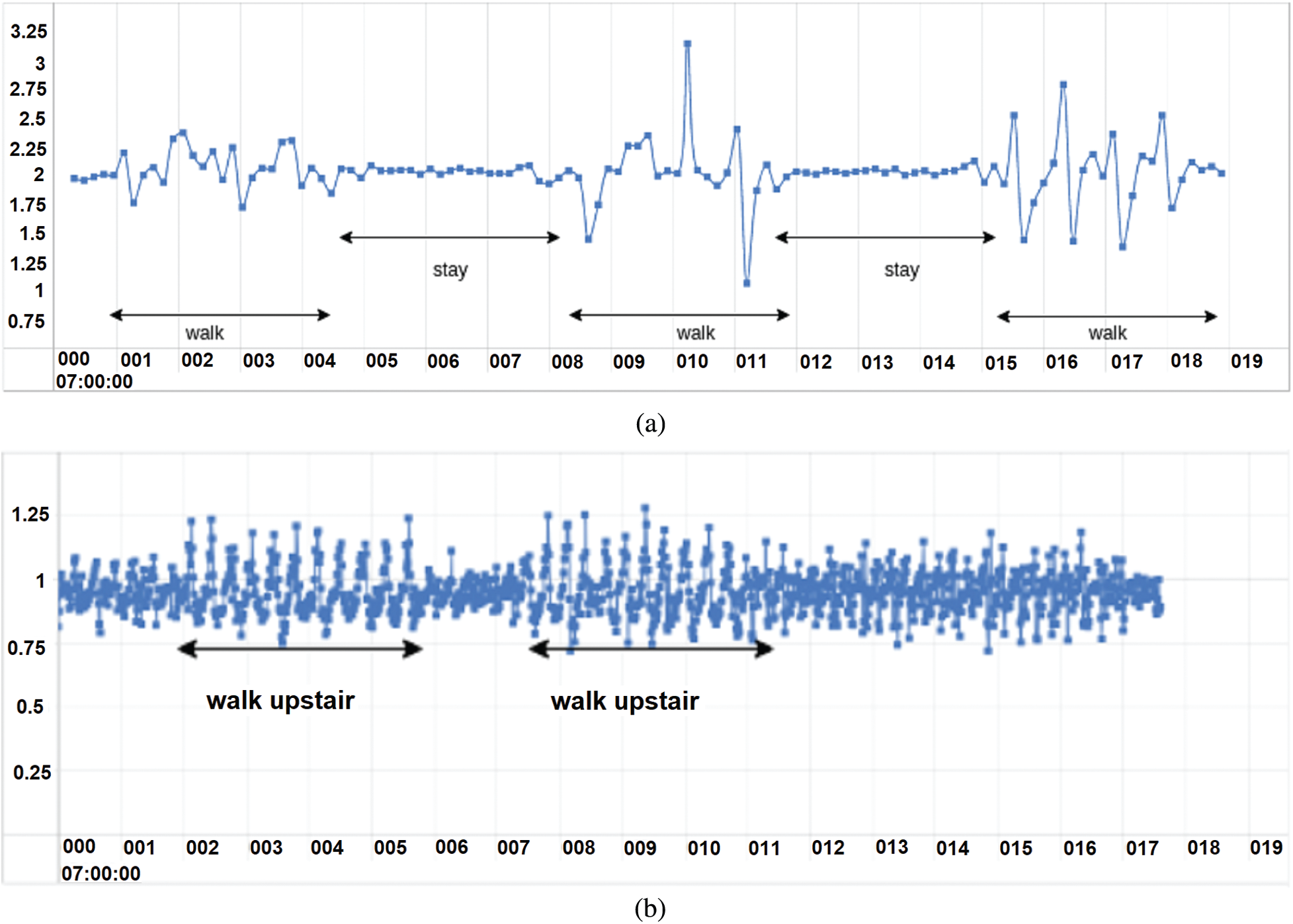
Figure 6: Graph of accelerometer reading. (a) When the human moves to another position, the accelerometer reading changes. When the human stops, the accelerometer reading is constant (b) Shows the accelerometer reading during a walking activity on a single floor and upstairs
Because of the limitations associated with holding the device, we proposed holding the device at four different angles because each person has his/her own way of holding a device, positioning it at the most comfortable angle. In this experiment, we devised a scenario testing the positioning of a device at different angles: 0
The aim of determining range walking is to find out how accurately the system can recognize the user activity. Using various thresholds and device positions in the testing scenario, we can distinguish between walking and stopping activities. Fig. 7 depicts the testing scenario range walking.
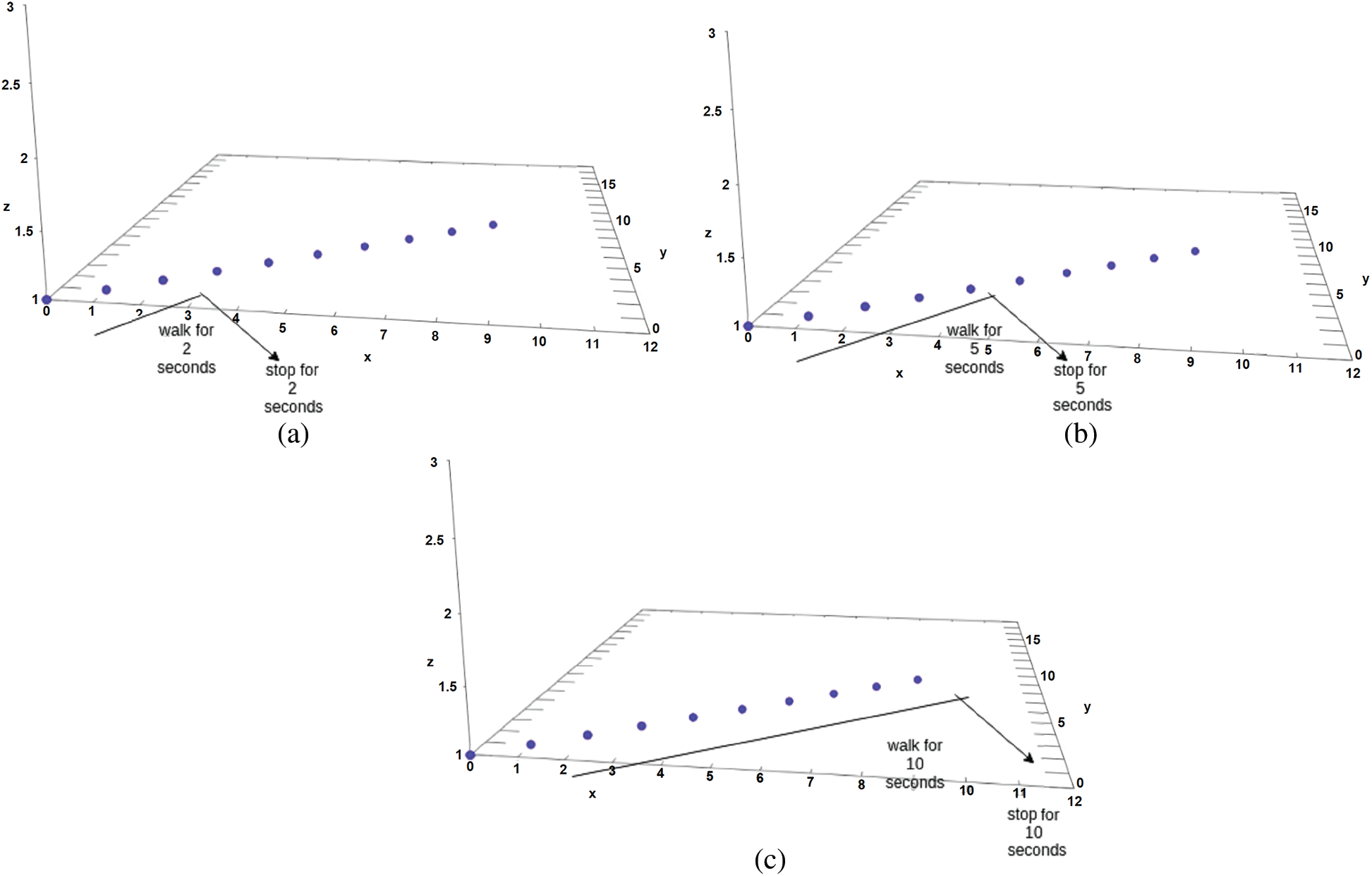
Figure 7: Testing scenario for range walking with 10 steps taken over a 20-second period. (a) 2 s for walking and 2 s for stopping (b) 5 s for walking and 5 s for stopping (c) 10 s for walking and 10 s for stopping
This section presents the results obtained from our testing scenarios. The focus of the evaluation is on how accurately the application sensor system recognized the number of steps in each testing scenario, and whether it was a walking or stopping activity.
In the testing scenario, we used threshold values ranging from 0.1 to 0.5. Tabs. 3–5 below show the number of steps recognized when SVM is over the threshold value.

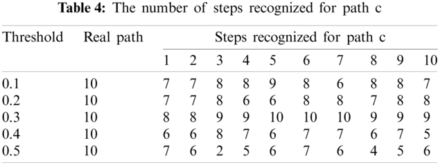
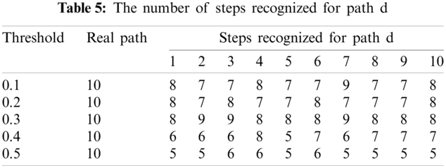
The tables above show that the smaller the threshold value, the better the system recognized the step because the sensor is more sensitive when comparing between the result of SVM and the threshold. The sensitivity of the threshold affects the ability of the device to process the vibration generated during the walking or stopping activity [11]. The system will recognize it as a step when the value of the SVM calculation is more than the threshold. Based on the formula proposed to calculate the accuracy, we obtain all the accuracy of the data. From the accuracy levels obtained, we calculate the average of each threshold accuracy and express this in Figs. 8a and 9. Note that the testing involved in many paths, only path a, c and d shown as an examples.
The graphs show that the optimum accuracy is achieved when the threshold value is 0.3, giving an average accuracy of about 88.75% for all paths in the scenario testing.
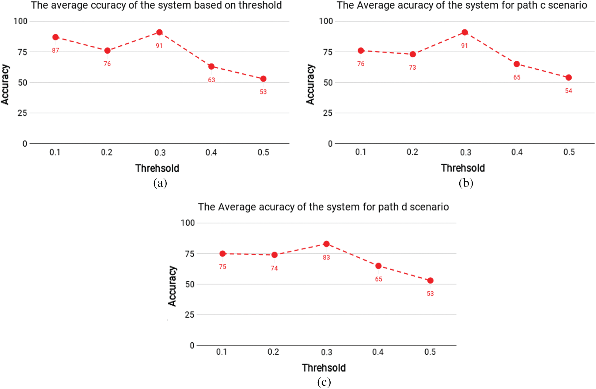
Figure 8: The level average of accuracy for paths c and d scenarios testing. (a) Scenario a (b) Scenario c (c) Scenario d
As mentioned previously, we used four device positions and thresholds ranging from 0.1 to 0.5. To determine the accuracy, we calculate the average of each scenario involving the device position. Below in Figs. 9a–9c representation of the average accuracy based on the position of the device.
From the figures, we can see that when the device is positioned at an angle of 0
Figure 9: The average level of accuracy. (a) Single floor with threshold = 0.3 (b) Single floor with threshold = 0.1 (c) Multi floor with threshold = 0.3
The results of our experiments show that the best threshold and the best device position can be used to distinguish between walking and stopping activities. We also examine the results of the range walking test in single-floor and multi-floor scenarios in order to determine the extent of its impact on results.
The level of accuracy based on the steps recognized are given in Tab. 6.
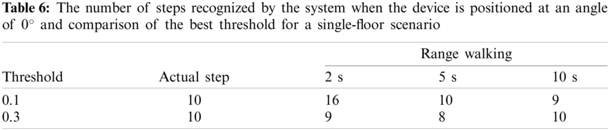
As can be seen from Fig. 10 the optimum accuracy is achieved when the threshold is 0.3.
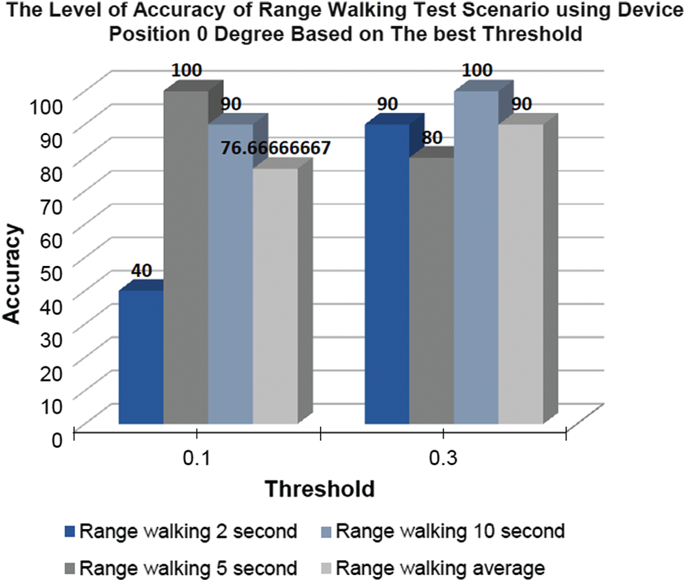
Figure 10: Graph visualization level of accuracy range walking test scenario based on the best threshold and device position is 0
The result of multi-floor testing scenario can be seen below in Tab. 7.
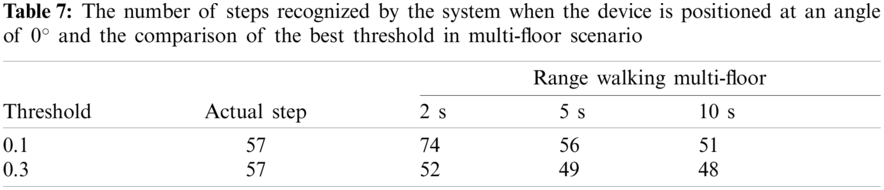
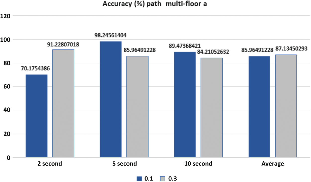
Figure 11: The level of accuracy (%): Number of steps recognized by the system; the comparison of the best threshold when the device is positioned at an angle of 0
The level of accuracy based on the number of steps recognized is shown in Fig. 11. Here, it is clear that the optimum accuracy is achieved when the threshold value is 0.3.
This paper investigates the reconstruction of trajectories in a multi-floor indoor environment by embedding a barometer sensor in a mobile device. The sensors involved are the accelerometer sensor to measure the acceleration force exerted on the mobile device when detecting motion, a magnetometer sensor to measure, and an additional barometer sensor to calculate the ambient air pressure, with the expectation that the ambient air pressure reading can indicate the number of floors in a building. Here, the steps are recognized accurately when 0.3 is the threshold and the device is positioned at a 0
There are several improvements that could be achieved by conducting future work in this area. First, the accuracy of the angle reading needs to be improved. Corrective data could be used to determine the level of accuracy of the compass in the mobile device. As we know, the compass in a mobile device is consumer-grade, and therefore not reliable enough to determine the angle accurately. Furthermore, to implement indoor trajectory reconstruction in an inter-building, several features need to be taken into consideration such as lifts, escalators, overlapping building and floors, and the movements of objects (i.e., walking or running).
Acknowledgement: The source of our implementations can be downloaded from the following URL: https://bit.ly/2T8UPzC.
Funding Statement: This research was supported by the Scientific Research Deanship, Saudi Electronic University (7732-CAI-2019-1-2-r).
Conflicts of Interest: The authors declare that they have no conflicts of interest to report regarding the present study.
1. Blake, A., Isard, M. (1997). The condensation algorithm-conditional density propagation and applications to visual tracking. Advances in Neural Information Processing Systems. Denver, Colorado, USA. [Google Scholar]
2. Alamri, S., Taniar, D., Nguyen, K., Alamri, A. (2020). C-tree: Efficient cell-based indexing of indoor mobile objects. Journal of Ambient Intelligence and Humanized Computing, 11(7), 2841–2857. DOI 10.1007/s12652-019-01397-w. [Google Scholar] [CrossRef]
3. Alamri, S. (2018). An efficient shortest path routing algorithm for directed indoor environments. ISPRS International Journal of Geo-Information, 7(4), 133. DOI 10.3390/ijgi7040133. [Google Scholar] [CrossRef]
4. Alamri, S. (2018). Spatial data managements in indoor environments: Current trends, limitations and future challenges. International Journal of Web Information Systems, 14(4), 402–422. DOI 10.1108/IJWIS-05-2018-0039. [Google Scholar] [CrossRef]
5. Guo, S., Xiong, H., Zheng, X. (2017). A novel semantic matching method for indoor trajectory tracking. ISPRS International Journal of Geo-Information, 6(7), 197. DOI 10.3390/ijgi6070197. [Google Scholar] [CrossRef]
6. Zheng, Y., Zhou, X. (2011). Computing with spatial trajectories. Berlin, Germany: Springer Science & Business Media. [Google Scholar]
7. Alamri, S., Taniar, D., Safar, M. (2014). A taxonomy for moving object queries in spatial databases. Future Generation Computer Systems, 37(2), 232–242. DOI 10.1016/j.future.2014.02.007. [Google Scholar] [CrossRef]
8. Alamri, S., Taniar, D., Safar, M., Al-Khalidi, H. (2014). A connectivity index for moving objects in an indoor cellular space. Personal and Ubiquitous Computing, 18(2), 287–301. DOI 10.1007/s00779-013-0645-3. [Google Scholar] [CrossRef]
9. Alamri, S., Taniar, D., Safar, M., Al-Khalidi, H. (2013). Spatiotemporal indexing for moving objects in an indoor cellular space. Neurocomputing, 122, 70–78. DOI 10.1016/j.neucom.2013.03.035. [Google Scholar] [CrossRef]
10. Alamri, S., Taniar, D., Safar, M. (2013). Indexing moving objects for directions and velocities queries. Information Systems Frontiers, 15(2), 235–248. DOI 10.1007/s10796-012-9367-8. [Google Scholar] [CrossRef]
11. Susanti, R. M., Adhinugraha, K. M., Alamri, S., Barolli, L., Taniar, D. (2018). Indoor trajectory reconstruction using mobile devices. 2018 IEEE 32nd International Conference on Advanced Information Networking and Applications. Cracow, Poland. [Google Scholar]
12. Dionti, T. A., Adhinugraha, K. M., Alamri, S. (2017). Indoor routing in three dimensional spaces. 5th International Conference on Information and Communication Technology. Malacca, Malaysia, IEEE. [Google Scholar]
13. Sathyaraj, B. M., Jain, L. C., Finn, A., Drake, S. (2008). Multiple UAVs path planning algorithms: A comparative study. Fuzzy Optimization and Decision Making, 7(3), 257–267. DOI 10.1007/s10700-008-9035-0. [Google Scholar] [CrossRef]
14. Guo, S., Xiong, H., Zheng, X., Zhou, Y. (2017). Indoor pedestrian trajectory tracking based on activity recognition. 2017 IEEE International Geoscience and Remote Sensing Symposium. Fort Worth, Texas, USA. [Google Scholar]
15. Klasnja, P., Pratt, W. (2012). Healthcare in the pocket: Mapping the space of mobile-phone health interventions. Journal of Biomedical Informatics, 45(1), 184–198. DOI 10.1016/j.jbi.2011.08.017. [Google Scholar] [CrossRef]
16. Alamri, S., Taniar, D., Nguyen, K. (2018). Vertical indexing for moving objects in multifloor environments. Mobile Information Systems, 2018(2), 1–15. DOI 10.1155/2018/4175298. [Google Scholar] [CrossRef]
17. Alamri, S. (2021). Independent map enhancement for a spatial road network: Fundamental applications and opportunities. ISPRS International Journal of Geo-Information, 10(1). DOI 10.3390/ijgi10010008. [Google Scholar] [CrossRef]
18. Au, A. W. S., Feng, C., Valaee, S., Reyes, S., Sorour, S. et al. (2013). Indoor tracking and navigation using received signal strength and compressive sensing on a mobile device. IEEE Transactions on Mobile Computing, 12(10), 2050–2062. DOI 10.1109/TMC.2012.175. [Google Scholar] [CrossRef]
19. Grzechca, D., Wróbel, T., Bielecki, P. (2014). Indoor localization of objects based on RSSI and mems sensors. 14th International Symposium on Communications and Information Technologies. Incheon, Korea, IEEE. [Google Scholar]
20. Permana, D. Y., Handojo, A., Andjarwirawan, J. (2013). Aplikasi indoor positioning system menggunakan android dan wireless local area network dengan metode fuzzy logic indoor positioning system. Jurnal Infra, 1(2), 13. [Google Scholar]
21. Developer, A. (2018). Sensors android. https://developer.android.com/guide/topics/sensors/sensors_overview.html#sensors-coords/. [Google Scholar]
22. Mazan, F., Kovarova, A. (2015). A study of devising neural network based indoor localization using beacons: First results. Computing and Information Systems Journal. University of the West of Scotland, 19(1), 15–20. [Google Scholar]
23. Rahok, S. A., Shikanai, Y., Ozaki, K. (2010). Trajectory tracking using environmental magnetic field for outdoor autonomous mobile robots. 2010 IEEE/RSJ International Conference on Intelligent Robots and Systems. Taipei, Taiwan, IEEE. [Google Scholar]
24. Condino, S., Fida, B., Carbone, M., Cercenelli, L., Badiali, G. et al. (2020). Wearable augmented reality platform for aiding complex 3D trajectory tracing. Sensors, 20(6), 1612. DOI 10.3390/s20061612. [Google Scholar] [CrossRef]
25. Sanchez, C. M., Hernandez-Guzman, V. M., Silva-Ortigoza, R., Antonio-Cruz, M., Merlo-Zapata, C. A. (2020). Intuitive planning, generation, and tracking of trajectory for wmr with mobile computing device and embedded system. IEEE Access, 8, 160627–160642. DOI 10.1109/ACCESS.2020.3021057. [Google Scholar] [CrossRef]
26. Cheon, H., Kim, B. K. (2019). Online bidirectional trajectory planning for mobile robots in state-time space. IEEE Transactions on Industrial Electronics, 66(6), 4555–4565. DOI 10.1109/TIE.2018.2866039. [Google Scholar] [CrossRef]
27. Li, J. C., Ran, M., Xie, L. (2021). Efficient trajectory planning for multiple non-holonomic mobile robots via prioritized trajectory optimization. IEEE Robotics and Automation Letters, 6(1), pp. 405–412. DOI 10.1109/LRA.2020.3044834. [Google Scholar] [CrossRef]
28. Lau, S. L., David, K. (2010). Movement recognition using the accelerometer in smartphones. Future Network and Mobile Summit. pp. 1–9. Florence, Italy, IEEE. [Google Scholar]
29. Feng, M. Q., Fukuda, Y., Mizuta, M., Ozer, E. (2015). Citizen sensors for SHM: Use of accelerometer data from smartphones. Sensors, 15(2), 2980–2998. DOI 10.3390/s150202980. [Google Scholar] [CrossRef]
30. Ibrahim, A., Eltawil, A. M., Na, Y., El-Tawil, S. (2020). Accuracy limits of embedded smart device accelerometer sensors. IEEE Transactions on Instrumentation and Measurement, 69(8), 5488–5496. DOI 10.1109/TIM.2020.2964912. [Google Scholar] [CrossRef]
31. Breunig, M., Bradley, P. E., Jahn, M., Kuper, P., Mazroob, N. et al. (2020). Geospatial data management research: Progress and future directions. ISPRS International Journal of Geo-Information, 9(2), 95. DOI 10.3390/ijgi9020095. [Google Scholar] [CrossRef]
32. Ye, H., Sheng, L., Gu, T., Huang, Z. (2019). Seloc: Collect your location data using only a barometer sensor. IEEE Access, 7, 88705–88717. DOI 10.1109/ACCESS.2019.2925460. [Google Scholar] [CrossRef]
33. Yu, M., Xue, F., Ruan, C., Guo, H. (2019). Floor positioning method indoors with smartphone’s barometer. Geo-Spatial Information Science, 22(2), 138–148. DOI 10.1080/10095020.2019.1631573. [Google Scholar] [CrossRef]
34. Weekly, E. (2018). Sensors power side channel attacks on android phones. https://www.electronicsweekly.com/news/design/university-electronics/sensors-power-side-channel-attacks-on-android-phones-2013-11/. [Google Scholar]
 | This work is licensed under a Creative Commons Attribution 4.0 International License, which permits unrestricted use, distribution, and reproduction in any medium, provided the original work is properly cited. |