Engineering & Sciences
| Computer Modeling in Engineering & Sciences |
DOI: 10.32604/cmes.2021.014669
ARTICLE
PotholeEye+: Deep-Learning Based Pavement Distress Detection System toward Smart Maintenance
1Korea Expressway Corporation, 77, Hyeoksin8-ro, Gimcheon-si, Korea
2Electronics and Telecommunications Research Institute (ETRI), 218 Gajeong-ro, Yuseong-gu, Daejun-si, Korea
3University of Science & Technology (UST), 217 Gajeong-ro, Yuseong-gu, Daejun-si, Korea
**Corresponding Author: Juyoung Park. Email: rainyday1998@gmail.com
Received: 19 October 2020; Accepted: 21 January 2021
Abstract: We propose a mobile system, called PotholeEye+, for automatically monitoring the surface of a roadway and detecting the pavement distress in real-time through analysis of a video. PotholeEye+ pre-processes the images, extracts features, and classifies the distress into a variety of types, while the road manager is driving. Every day for a year, we have tested PotholeEye+ on real highway involving real settings, a camera, a mini computer, a GPS receiver, and so on. Consequently, PotholeEye+ detected the pavement distress with accuracy of 92%, precision of 87% and recall 74% averagely during driving at an average speed of 110 km/h on a real highway.
Keywords: Pavement distress; detection; classification; convolutional neural network; deep learning; video analysis
A pothole is a type of distress in the pavement, the surface of a roadway, where a portion of the road material has broken away, leaving a hole [1]. Potholes not only interfere with comfortable driving on the roadway, but also lead to vehicle damage and/or traffic accidents. For highways where driving is allowed at a speed between 80 and 110 km/h, in particular, risks are further increased by serious damage to road pavement, such as potholes. Therefore, the road management agencies daily or specially check the surface of a roadway by human inspections in order to prevent such situations (e.g., traffic accidents). Particularly, the Korea Expressway Corporation, one of the road management agencies, identifies pavement damage that requires immediate repair, such as potholes, through daily and special inspections, and repairs such damage within 24 h of detection. However, the human inspections are time consuming and labor-intensive task. Besides, theses system by the human inspections cannot guarantee early detection.
As the development of IT technology has been consistently accelerated, studies have been actively conducted to detect potholes that may threaten the safety of road users automatically using such technology [2–6]. Initially, acceleration sensors were mounted on vehicles and the displacement values of sensors were measured to detect potholes [3,4]. However, for studies that utilized acceleration sensors, detection was not possible when the vehicle avoided potholes during driving. Even when the vehicle did not avoid potholes during driving, the false detection rate was high because the displacements of other road surface installations, such as manholes, pavement, and pier boundaries, were similar. To overcome this drawback, studies to detect potholes by analyzing video and image data, such as from black boxes, captured at the viewing angle of a road user have been actively conducted recently [5–7].
In this paper, we propose a novel mobile system, called PotholeEye+, which is an extension version of PotholeEye [8] for automatically monitoring the surface of a roadway and providing real-time analysis of images. PotholeEye+ has been newly developed to be effective, simple to use, sustainable and reliable. Since the human inspections is time consuming and labor-intensive task, in this paper we focus on how to effectively maintain the pavement distress, such as a pothole, in view of the road management agencies. Toward that goal, PotholeEye+ involves a camera and a mini-computer attached to vehicle as well as a remote server for history information that interconnects these devices. PotholeEye+ analyzes video images from the camera on the mini-computer and transmits analyzing results to remote server to save historical information. Fig. 1 show a conceptual diagram for pavement distress detection of PotholeEye+ which consist of three steps, (a) data collection step, (b) real-time detection step, and (c) detected image recording step. While a road manager is driving, PotholeEye+ automatically monitors the pavement images in real-time video clip and detects the distress by analyzing the images. The results of this analysis are conveyed to another staff, located at a remote office, to support decision whether to require immediate repair or not in real-time. PotholeEye+ transmits the analyzing results to remote server in order to save historical information at the same time.
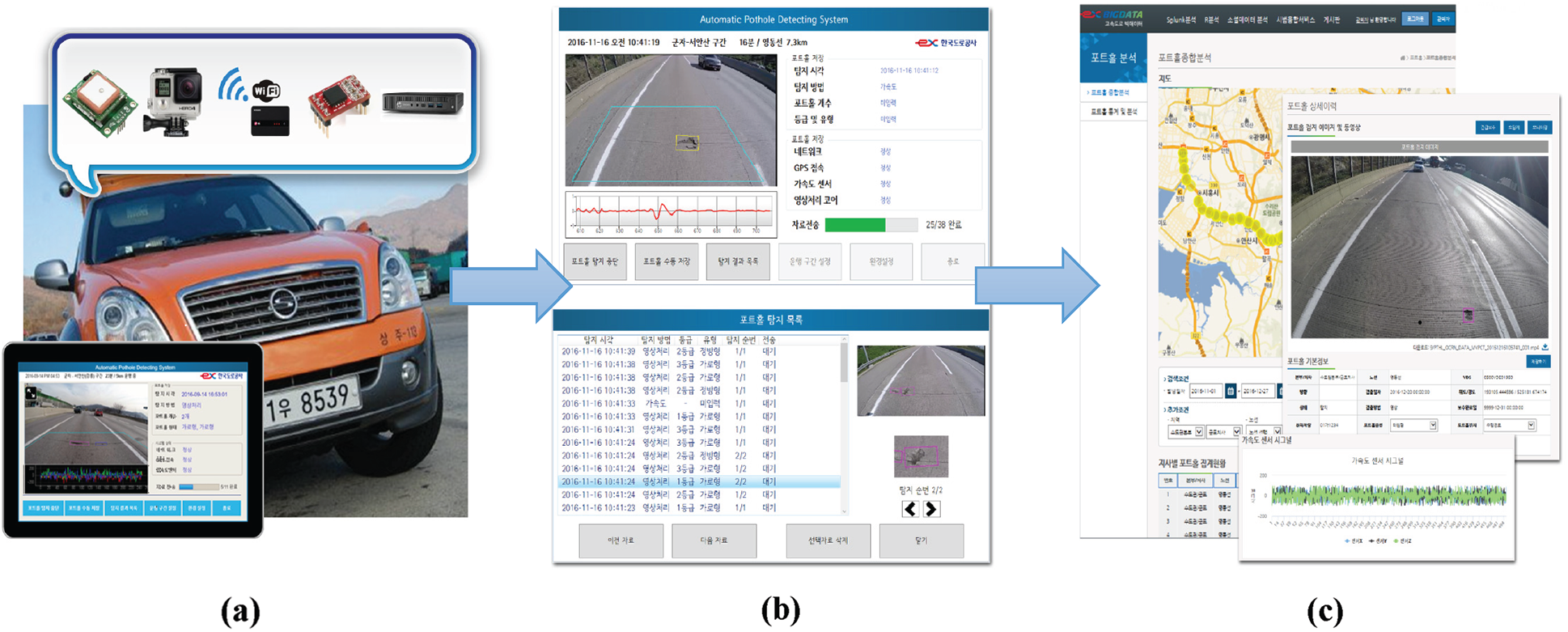
Figure 1.: Conceptual diagram for real-time road pavement distress detection; (a) data collection step, (b) real-time detection step, and (c) detected image recording step
Hence, first, PotholeEye+ allows the road management agencies to inspect the surface condition of a roadway in a fast and convenient manner. This maximizes the effectiveness of maintenance task for pavement distress. Second, PotholeEye+ detects various types of pavement distress present on the road, including potholes. It is necessary for road managers to manage portholes and other road surface damages because a collection of small damage, such as cracks, may suddenly cause serious damage as with the damage caused by potholes. Third, PotholeEye+ makes it possible to track and manage the road pavement damage status by recording the detected distress information. Thus, video clips and images collected and detected over a long period can be used to develop a road pavement damage prediction system and various decision-making support systems essential for road maintenance, such as the selection of areas in need of urgent maintenance.
Studies to detect distress to roadway pavement automatically have been actively conducted, and they can be classified into methods that use acceleration sensors, images, and laser scanning [4]. In this section, studies on image-based road pavement damage detection, which is known to be relatively less expensive than other methods and able to detect a broader area, are introduced.
Koch et al. proposed a method of detecting potholes by acquiring images using a small robot watching the road surface [6,7]. In the method proposed by them first [6], the defective part and non-defective part of an image were divided using the shape of the histogram, and the shape and texture extracted from the defective part were compared with the texture extracted from the non-defective part to determine potholes. Subsequently, the aforementioned study was improved using a tracking algorithm that utilized continuous image frames [7]. Buza proposed a method of identifying potholes by dividing an image using the OTSU thresholding method, extracting shapes using the spectral clustering algorithm, and extracting horizontal and vertical regions [9].
Huidrom proposed the critical distress detection and measurement and classification (CDDMC) algorithm for the automatic detection and classification of road pavement damage [10]. This algorithm was developed by considering a collective set of three visual properties of potholes, cracks, and patches. This collective set of identified visual properties incudes the image texture, the shape factor, and the dimension of a pothole and patch. Especially, for extracting visual properties, the circularity of the object area, average width, and standard deviation of the pixel brightness were used. This CDDMC algorithm was composed of the steps of (a) image enhancement, (b)image segmentation, (c) visual properties extraction of objects, (d) detection and classification of distresses by decision logic, and (e) quantification.
Among the studies introduced above, the studies by Koch and Kim aimed to detect pavement distress automatically based on images [6,11–14]. However, the study by Buza utilized manually cropped images for evaluation, and the study by Huidrom evaluated only the user-defined area. Therefore, it appears that further investigation is required to apply the studies to actual environments [9,10]. The study by Koch utilized the images acquired by a small robot, but the fabrication of the small robot is expensive, and it is difficult to use it universally in high-speed driving environments [7]. Shebin et al. proposed a pothole detection system using a single deep neural network method based on smartphone [12]. Kumar et al. proposed a pothole detection model based on transfer learning, faster region-based convolutional neural network (F-RCNN) and inception-V2 [13]. Jung-Cheng et al. developed a pothole image generation system, which can improve the performance of the detection model by virtual images. In this paper, we proposed a more practical method to detect pavement distress while driving in real time using a camera mounted on a vehicle, in terms of more effectively managing road surface distress.
3 Methods of Automatic Detection of Pavement Distress
The main work towards realizing PotholeEye+ is to detect the pavement distress automatically in real-time. To solve this work, PotholeEye+ technically combines traditional image processing methods and a classification method after batching the pre-trained model as shown in Fig. 2.
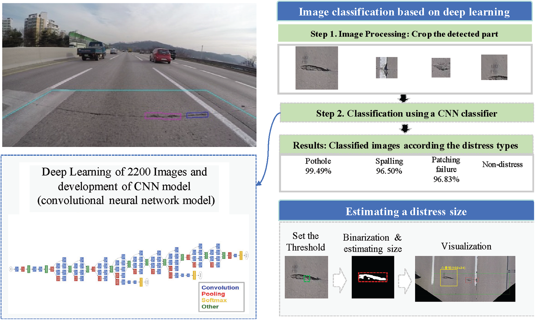
Figure 2.: Block diagram for image classification and distress estimation
First, PotholeEye+ processes the video image from a camera attached to the vehicle in real-time. The results of this step are cropped images containing only the region of interest (ROI). Fig. 3 represents image processing step in detail. PotholeEye+ applies an orthogonal projection [15] in order to reduce the deviation of the input images according to the camera position. Let V be a subspace of
Then PotholeEye+ performs binarization using multi-thresholding approach after noise removal. In order to extract feature points from an image, the binarization method is a common method, but if the threshold is fixed and processed, there is a difficulty in the binarization process to extract the feature points according to the image. Fig. 4 shows how feature points are extracted according to the threshold setting. If the threshold value, T, is set to 140, the feature points are well extracted, but if T is lowered in the order of 100, 50 and the result is seen, the feature gradually disappears such as (c) and (d) in Fig. 4. To overcome this limitation of binarization, in the early stages of this study, we tried to extract feature points with the adaptive threshold technique, which is the core of the CDDMC algorithm [10]. The adaptive thresholding is to convert enhanced image into binary image with black pixels representing objects of interest. However, the adaptive threshold technique was excluded because it was difficult to extract in the case of distress included in the lane. Therefore, we apply binarization using multi-thresholding approach. Fig. 3e shows the binarization technique applied in this study, and it can be seen that various feature points can be found in each binarized image, such as a red area.
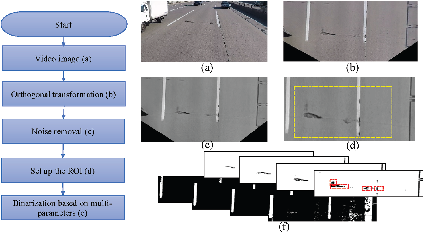
Figure 3.: Image processing step for cropping the ROI (Region of interest): (a) Video image as input data, (b) Orthogonal transformation, (c) Noise removal, (d) Set up the ROI, (e) Binarization based on multi-parameters

Figure 4.: Binarization examples according to the threshold value, T; (a) Gray scale image, (b)T:140, (c) T: 50, (d) T: 100
Next, PotholeEye+ uses a Convolutional Neural Networks (CNNs) model, which is known to have achieved good performance in image classification [16]. CNN can be divided into a part that extracts features of an image and a part that classifies the class. The feature extraction area is composed of several layers of convolution and pooling layers. Convolution Layer is an essential element that applies a filter to the input data and reflects the activation function. The pooling layer next to the convolution layer is an optional layer. At the end of the CNN, a Fully Connected layer is added for image classification. A flatten layer is placed between the part that extracts the features of the image and the part that classifies the image.
We reviewed GoogleNet [17], VGGNet [18], and AlexNet [19], which are well known as CNN model. At Large Scale Visual Recognition Challenge (ILSVRC) 2014, GoogLeNet, made by Google, is known to have won VGGNet with a slight margin. The basic structure of GoogleNet announced by Google was designed to obtain features of different scales by applying convolutional filters with different sizes to the same layer and solved the problem of computation in deep layers using 1 × 1 convolution. VGGNet was developed by studying the effect of depth on the network (Layer). At ILSVRC 2014, both GoogLeNet and VGGNet recorded very low error rates of 7%. AlexNet is also a model that won ILSVRC 2012 and consists of a total of 5 convolution layers and 3 full-connected (FC) layers, and the last FC Layer uses the soft-max function as an active function for classification.
To select the competitive CNN model, we evaluated these CNN models. For evaluation, we first prepared 50 224 ∗ 224 color images for each class and increased the number of images to 30,000 using data augmentation technique to solve the small data problem. In other words, GoogLeNet, VGGNet, and AlexNet were trained equally with 30 epochs, using totally 180,0000 images. As a result of the test, GoogLeNet showed the highest accuracy as shown in Tab. 1 and was finally selected.
Table 1: Competitive results for CNN model selection

During driving, PotholeEye+ only classified images into types of distress using a pre-trained CNN model. In other words, 1) PotholeEye+ loads a CNN model prepared in advance, 2)applies CNN classifier to cropped area extracted from image processing step. As a result, 3)major types of distress are extracted and the others are discarded. PotholeEye+'s CNN model is generated by iterative training based on image sets, that are automatically extracted by the image processing system [15] and labeled by humans under the supervision of a roadway manager. In more detail, we prepared 31,200 images of size 224 × 224 which are categorized distress into 4types for main distress, pothole and patching failure in asphalt pavement, spalling and punch-out in concrete pavement, and 22 non-main or non-distresses such as tire mark and shadow, as shown in Fig. 5. As a result, we categorized the pavement distress in the extracted image set into 26 types and prepared 1,200 images for each type for training. Although training data are images representing the type of pavement distress, the image generally has a lot of influence of light and the pavement distress is a random shape. Since PotholeEye+ needs to be able to recognize shadows, darkness, and inverted shapes, we applied the data augmentation technique to our training data. Fig. 6 shows parts of the training data to generate a CNN model and results of applying the augmentation technique such as brightness, left and right inversion.

Figure 5.: Types of the distress considered in PotholeEye+; in asphalt pavement, (a) pothole and (b) patching failure; in concrete pavement, (c) spalling and (d) punch-out; otherwise, such as (e) tire mark and (f) shadow
In addition, PotholeEye+ provides a roughly size of the damaged area in a cropped image that are identified as a type of pavement distress. Estimating a distress size performs the following processes: calculation of a mean value of the pixels in the central area, binarization using the mean value, detection of binary large objects (BLOBs) which is small objects are judges as noise and only objects larger than certain size, and lastly measurement width and height about the detected BLOBs.
We conducted PotholeEye+ on the highway involving real settings, a camera, a mini computer, a GPS receiver, and so on, in vehicle from Hyundai Motor Company as shown in Fig. 7. Tab. 2 shows a list of sections on highway driven for PotholeEye+'s test and we drove 102 km with an average speed of 110 km/h. To access the quantitative performance, we tested PotholeEye+ in two point of view. The first is the detection performance of the PotholeEye+ for pavement distress and the second is how much time has been reduced for road inspection when using PotholeEye+.

Figure 6.: Training data images; (a) parts of the training dataset and (b) parts of results of applying the data augmentation

Figure 7.: Pictures of device attached to vehicle; (a) front view of the vehicle with GPS receiver, (b) rear view of the vehicle with camera, (c) touch screen monitor, (d) mini-computer, and (e)GoPro Hero Camera
We evaluated the distress detection (classification) results of the PotholeEye+ during driving a total of 4 sections, a distance of 102 km as listed in Tab. 2. Accuracy, precision and recall were considered [20]. The experiment results showed that PotholeEye+ achieved an accuracy of 91.66%, a precision of 87.07% and a recall of 74.39%. Detailed information is as listed in Tab. 3. As a result of the experiment, we found that there is a need to intensively supplement the detection model for the distress of asphalt pavement because there are many cases of misclassification of the distress caused by the asphalt pavement. Also, parts of false positive were difficult to distinguish even by human, as shown in Fig. 8. Figs. 8a and 8c–8e are all normal patching, but PotholeEye+ classified into the pavement distress, such as pothole and spalling, and (b) is narrow crack and (c) is crack but misclassified into spalling.

Figure 8.: Misclassified cases; (a), (c), (d), and (e) are all normal patching, but PotholeEye+ classified into the pavement distress, such as pothole and spalling; (b) is narrow crack and (c) is crack but misclassified into spalling
Table 2: Description about the sections on highway driven for PotholeEye+ test

Next, to evaluate how short the inspection time for finding pavement distress on highway was reduced, we have been running PotholeEye+ for eight branches of highway management under the Korea Expressway Corporation for 6 months. We compared the inspection time of PotholeEye+ with the human inspectors. As a result, we confirmed that the inspection time was reduced by 3times as shown in Tab. 4. Furthermore, we received positive feedback from the human inspectors that anyone can check the pavement distress using PotholeEye+, and that the risk of accidents that may occur during the check can be reduced.
Table 3: Detection results from for PotholeEye+ for each pavement distress type

Table 4: Comparison results with the inspection time and the features

PotholeEye+ installed in the terminal of the driving vehicle instantly detects road surface damage at the current location through the real-time analysis of the data collected from the video sensor. Fig. 9 shows PotholeEye+ installed on a vehicle to check the road surface. PotholeEye+ has a weak point of snow and rain because the camera is attached to the outside of the vehicle. Hence, we made a cover to prevent the camera exposed to the outside from malfunctioning due to snow or rain.

Figure 9.: PotholeEye+ installed on a vehicle to check the road surface; (a) front view; (b) back view; (c) cover for a camera exposed to the outside
Fig. 10 shows a screenshot of PotholeEye+ running on a mini-computer installed in the vehicle. The detected images by PotholeEye+ are sent to the road manager through MMS along with GPS location information and they are also transmitted to a remote server. The server stores and manages the detailed information detected at each time along with the basic information on the road pavement of each section of the route based on a map.

Figure 10.: Screenshot of PotholeEye+ running on mini-PC installed in a vehicle
In this paper, we present the end-to-end operation of PotholeEye+. Repeated driving experiments on a highway confirmed that PotholeEye+ could be used to inspect the pavement condition in a fast, accurate and convenient manner. However, it was also confirmed that the detection accuracy of PotholeEye+ must be improved for it to be applied effectively to the automation of pavement condition inspection activities in actual highway environments. In the future, the detection performance will be improved by securing long-term image data through repeated driving, preparing detailed criteria for pavement distress based on the data, and applying the latest technologies. Moreover, the ability of detecting small distress, such as small cracks, will be improved by supplementing the image processing algorithm through the application of line component extraction to the lower section of an image, and the system will be gradually improved through comparative experiments with the latest technologies.
Funding Statement: The authors received no specific funding for this study.
Conflicts of Interest: The authors declare that they have no conflicts of interest to report regarding the present study.
1. Miller, J. S., Bellinger, W. Y. (2003). Distress identification manual for the long-term pavement performance program. FHWA-RD-03-31. Federal Highway Administration. [Google Scholar]
2. Yu, B. X., Yu, X. (2006). Vibration-based system for pavement condition evaluation. International Conference on Applications of Advanced Technology in Transportation, Chicago. [Google Scholar]
3. Mednis, A., Strazdins, G., Zviedris, R. (2011). Real time pothole detection using android smartphones with accelerometers. International Conference on Distributed Computing in Sensor Systems and Workshops, Barcelona. [Google Scholar]
4. Jo, Y., Ryu, S. (2016). Real time pothole detection system based on video data for automatic maintenance of road surface distress. Journal of KIISE: Computing Practices and Letters, 22(1), 8–19. DOI 10.5626/KTCP.2016.22.1.8. [Google Scholar] [CrossRef]
5. Danti, A., Kulkarni, J. Y., Hiremath, P. S. (2012). An image processing approach to detect lanes, pot holes and recognize road signs in Indian roads. International Journal of Modeling and Optimization, 2(6), 658–662. DOI 10.7763/IJMO.2012.V2.204. [Google Scholar] [CrossRef]
6. Koch, C., Brilakis, I. (2011). Pothole detection in asphalt pavement images. Advanced Engineering Informatics, 25(3), 507–515. DOI 10.1016/j.aei.2011.01.002. [Google Scholar] [CrossRef]
7. Koch, C., Brilakis, I. (2011). Improving pothole recognition through vision tracking for automated pavement assessment. EG-ICE Workshop on Intelligent Computing in Engineering Twente. [Google Scholar]
8. Park, J., Im, K., Lee, J. H. (2019). Demo: potholeEye–How can we effectively maintain in the pavement distress? International Conference on Mobile Systems, Applications, and Services, Seoul. [Google Scholar]
9. Buza, E., Omanovic, S., Huseinovic, A. (2013). Pothole detection with image processing and spectral clustering. International Conference on Information Technology and Computer Networks, Antalya. [Google Scholar]
10. Huidrom, L., Das, L. K., Sud, S. K. (2013). Method for automated assessment of potholes, cracks and patches from road surface video clips. Procedia—Social and Behavioral Sciences, 104, 312–321. DOI 10.1016/j.sbspro.2013.11.124. [Google Scholar] [CrossRef]
11. Kim, Y. R., Kim, T., Ryu, S. (2014). Pothole detection method in asphalt pavement. Journal of the Institute of Electronics and Information Engineers, 51(10), 248–255. DOI 10.5573/ieie.2014.51.10.248. [Google Scholar] [CrossRef]
12. Ozeki, K., Umeda, T. (1984). An adaptive filtering algorithm using an orthogonal projection to an affine subspace and its properties. Electronics and Communications in Japan (Part I: Communications67(5), 19–27. DOI 10.1002/ecja.4400670503. [Google Scholar] [CrossRef]
13. Silvister, S., Komandur, D., Kokate, S., Khochare, A., More, U. et al. (2019). Deep learning approach to detect potholes in real-time using smartphone. IEEE Pune Section International Conference, Pune. [Google Scholar]
14. Kumar, A., Chakrapani, K., Kalita, D. J., Singh, V. P. (2020). A modern pothole detection technique using deep learning. International Conference on Data, Engineering and Applications, Bhopal. [Google Scholar]
15. Tsai, J. C., Lai, K. T., Su, J. J., Siao, C. Y., Hsu, Y. C. (2020). Learning pothole detection in virtual environment. International Automatic Control Conference, Hsinchu. [Google Scholar]
16. Gu, J., Wang, Z., Kuen, J., Ma, L., Shahroudy, A. et al. (2018). Recent advances in convolutional neural networks. Pattern Recognition, 77, 354–377. DOI 10.1016/j.patcog.2017.10.013. [Google Scholar] [CrossRef]
17. Szegedy, C., Liu, W., Jia, Y., Sermanet, P., Reed, S. (2014). Going deeper with convolutions. IEEE Conference on Computer Vision and Pattern Recognition, Boston. [Google Scholar]
18. Simonyan, K., Zisserman, A. (2015). Very deep convolutional networks for large-scale image recognition. IEEE Conference on Computer Vision and Pattern Recognition, Boston. [Google Scholar]
19. Krizhevsky, A., Sutskever, I., Hinton, G. E. (2012). Imagenet classification with deep convolutional neural networks. International Conference on Neural Information Processing Systems, Lake Tahoe. [Google Scholar]
20. Powers, D. M. (2011). Evaluation: From precision, recall and F-measure to ROC, informedness, markedness and correlation. Journal of Machine Learning Technologies, 2(1), 37–63. https://arxiv.org/abs/2010.16061. [Google Scholar]
 | This work is licensed under a Creative Commons Attribution 4.0 International License, which permits unrestricted use, distribution, and reproduction in any medium, provided the original work is properly cited. |