| Computer Modeling in Engineering & Sciences |
DOI: 10.32604/cmes.2021.014665
ARTICLE
A Numerical Investigation of the Stress Relief Zones Around a Longwall Face in the Lower Seam for Gas Drainage Considerations
1Faculty of Architecture and Civil Engineering, Huaiyin Institute of Technology, Huai’an, 223001, China
2Mining and Mineral Resources Engineering, Southern Illinois University, Carbondale, Illinois, 62901, USA
3School of Mechanics and Civil Engineering, China University of Mining & Technology (Beijing), Beijing, 100083, China
4Department of Civil Engineering, University of Arkansas, Fayetteville, AR 72701, USA
5School of Energy and Mining Engineering, China University of Mining & Technology (Beijing), Beijing, 100083, China
*Corresponding Author: Chunlei Zhang. Email: leizhewudi@hyit.edu.cn
Received: 18 October 2020; Accepted: 06 January 2021
Abstract: Extraction of a protective coal seam (PVCS)-below or above a coal seam to be mined with the potential of coal and gas outburst risk-plays an important role not only in decreasing the stress field in the surrounding rock mass but also in increasing the gas desorption capacity and gas flow permeability in the protected coal seam (PTCS). The PVCS is mined to guarantee the safe mining of the PTCS. This study has numerically evaluated the stress redistribution effects using FLAC3D model for a longwall face in Shanxi Province. The effects of mining depth, mining height and inter-burden rock mass properties were evaluated using the stress relief angle and stress relief coefficient. Vertical stress distribution, stress relief angle and stress relief coefficient in the PTCS were analyzed as the face advanced in the PVCS. The results showed that the stress relief achieved in different locations of the PTCS varied as the face advanced. Sensitivity analyses on the pertinent variables indicate that the stress relief in the PTCS is affected most by the mining depth followed by the inter-burden lithology and the mining height. Furthermore, the elastic moduli of different layers within the inter-burden rock mass are more important than their uniaxial compressive strength (UCS) and Poisson’s ratio. These observations can guide gas drainage borehole design to minimize the accidents of coal and gas outbursts.
Keywords: Methane drainage; longwall mining; protective/protected coal seam; multiple seams; FLAC3D software; stress relief zones
1 Background and Problem Statement
Over 50% of the coal mines in China mine coal seams with high gas content. The definition of high gas content coal mine is very complex but the commonly used indicators are the absolute gas emission (AGE) and the relative gas emission (RGE). When the AGE is greater than or equal to 40 m3/min, or the RGE is greater than or equal to 10 m3/t, the mine can be regarded as having high gas content [1]. Similarly, about 44% of all coal mines in China are also known to have high coal and gas outburst risk [2]. The coal and gas outburst risks seriously threaten coal mine safety and reduces operations productivity [3]. The National Bureau of Statistics reported (2017) that 2,171 workers died from gas-related accidents in 2005 alone, and gas-related accidents accounted for about 64% of all coal mine accidents from 2006 to 2016 [4]. Implementation of various comprehensive gas prevention and control measures in coal mines has greatly decreased fatal injuries in recent years. Since the gas content and gas pressure in coal seams potentially increases with the mining depth, gas and coal outburst accidents continue to threaten the safety of coal mines.
Most coal seams in China are characterized by low gas pressure, low gas saturation, low permeability due to their high degree of metamorphism. This has resulted in low success in gas drainage before coal mining [4–7]. Many researchers have suggested that achieving stress relief in coal mass can improve gas permeability of coal and rock mass, which can enhance gas extraction, and reduce gas content and pressure [2,8–14]. After decades of theoretical studies and field trials, the concept of excavating the PVCS has proved to be an effective method to reduce coal and gas outburst risk in the PTCS [13,15]. The 139th article in the “Safety Regulations for Coal Mines” stipulates: “In the case of mining coal seam group with coal and gas outburst risk, mining protective layers must be adopted as a measure to prevent coal and gas outburst” [1].
2 Description of the Case Study Mine
The mine is located in NW China around Gaoping City of Shanxi Province (Fig. 1). The current mine production is 5 Mt of raw coal annually. There are 16 coal seams in the area but #3 and #15 are the two primary minable seams with some portions of #2 and #8 seams also minable. The coal seams depths range from 300 to 800 m with strike in the E-W. Initial longwall panels were 400 m deep. The gas content in the coal field varies and it increases from about 0.4 m3/t in the eastern part to about 25 m3/t in the western part. The mine is currently extracting #3 low permeability coal seam with methane content of 6.5–15.09 m3/t.
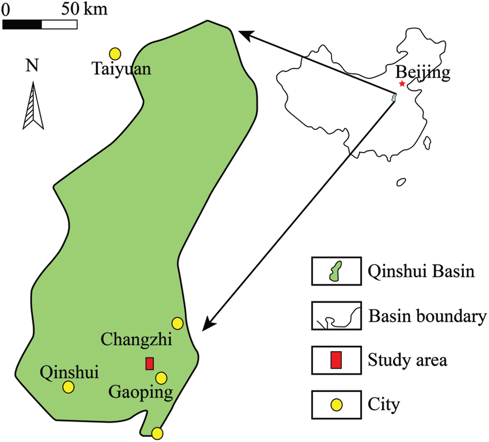
Figure 1: Location of Changping coal mine in Shanxi Province
Tab. 1 shows the selected parameters of the major minable coal seams in the study area. The thickness of #2 and #3 coal seams varies 0–2.95 m and 4.67–6.58 m, respectively. Selected parameters of #3 and #8 coal seams are listed in Tab. 2 [13]. Seams are characterized by low permeability and low hardness. The gas content of #3 coal seam can reach up to 15.09 m3/t. Gas outburst and dynamic gas emissions frequently occur during the excavation of the roadways for #4 306 longwall faces. The #8 coal seam is a non-outburst prone coal seam with gas content of only 2–3 m3/t. In order to eliminate coal and gas outburst risk in #3 coal seam, the lower #8 coal seam was selected as the PVCS. The LW84306 (Longwall 84306) face (Fig. 2) is located in #8 seam with panel width and length of 300 and 1128 m. The average mining thickness is 1.22 m and ranges from 1–3 m. The LW4306 (Longwall 4306) working face mines #3 seam of 5.23 m with an average dip angle of
Table 1: Selected parameters of the major minable coal seams
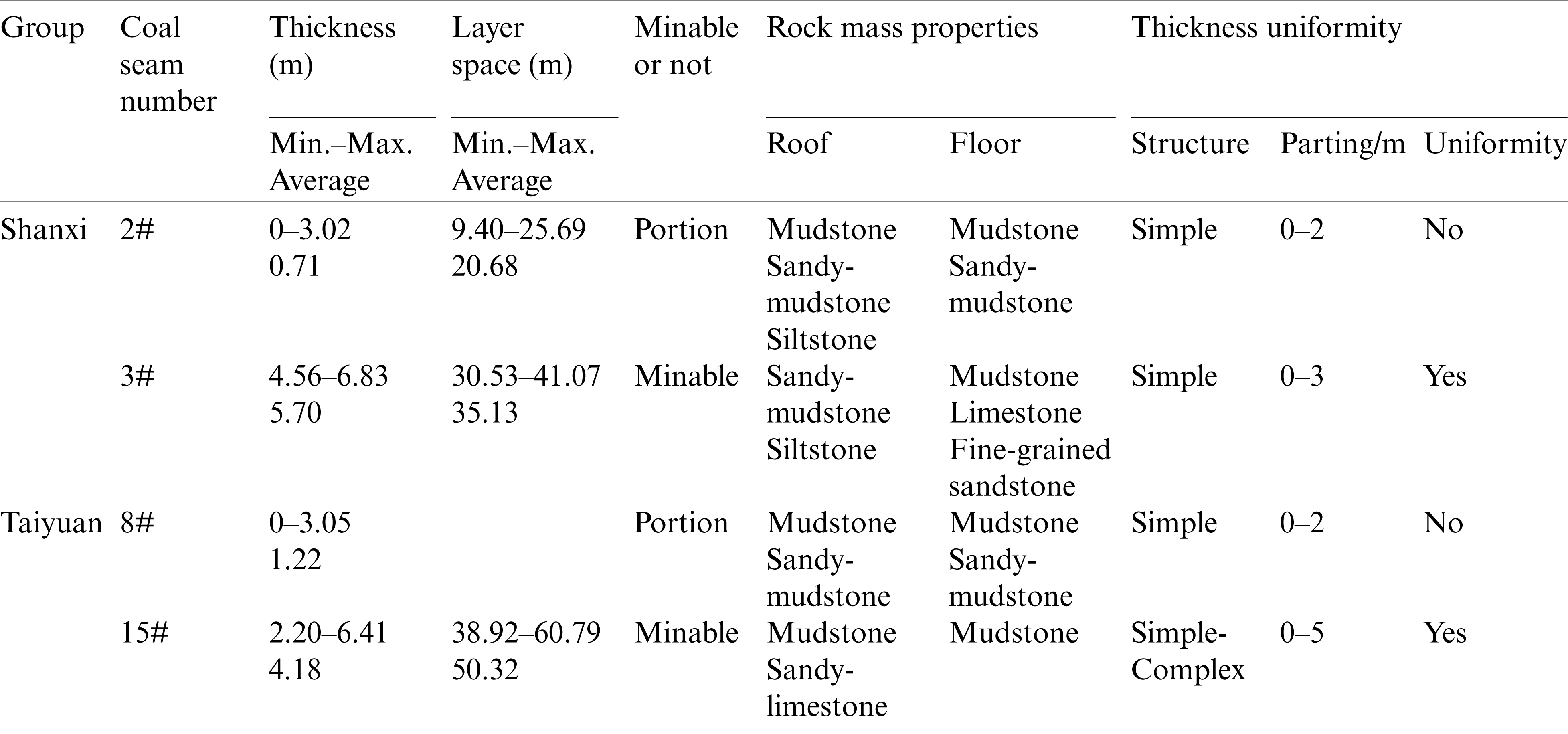
Table 2: Selected parameters of No. 3 coal seam
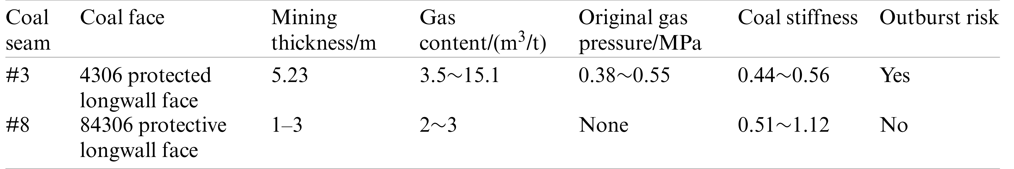
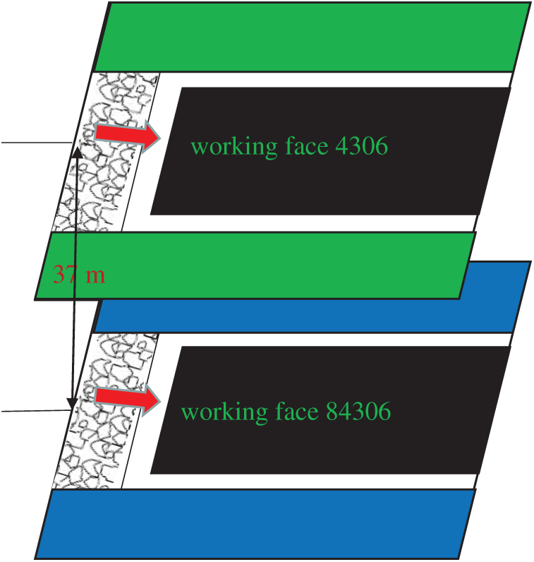
Figure 2: Layout of spatial locations of working faces
It is desired to have a good understanding of stress redistribution around a longwall face, and associated fracture development, and gas flow behavior during the mining process and then effectively apply the PVCS concept in the field. A few studies on these topics have been conducted under the condition of extracting single seam and multiple seams [13–15]. Formation and evolution of gas-flow channels have been investigated around the front and side abutment pressure areas, floor and gob behind the coal face area during longwall mining [16–21]. Recently, research studies have been conducted on the mechanism of strata deformation and stress distribution under PVCS mining [22–26]. Huang et al. [26] used a numerical method to model the stress redistribution in the PTCS during the excavation of an upper PVCS. The results showed that the increase in the mining height of the upper PVCS promotes pressure release in the PTCS while the hard rock floor of PVCS reduces the pressure release. Yang et al. [27] used 2D and 3D numerical models to investigate mining-induced stress and the extraction effect on pressure relief for large mining height with upward mining sequence. The results showed that high stiffness and thick strata in the main roof are important in delaying the caving time and decreasing void ratio of the caved rock. The compressive and tensile zones around the coal seam being mined are controlled by the number, thickness, and strength of the stiff and thick layers. In order to control coal and gas outbursts in a pressure-relieved boundary areas, Liu et al. [28] experimented with a mining method based on laboratory experiments and field measurements in Qingdong mine. The results showed that coal mass permeability has a negative exponential relationship with the vertical stress in the pressure-relief boundary areas. Additionally, coal permeability in these areas is significantly different with that around the center of the pressure-relief area. Coal and gas outburst accidents are likely to be triggered in these areas. Effective precautions against coal and gas outburst accidents can be implemented based on stress re-distribution characteristics. Cao et al. [29] obtained the protection range of the lower PVCS in a thin coal seam through FLAC3D simulation in order to promote gas extraction. Cheng et al. [30] conducted theoretical analyses and physical experiments to study the characteristics of the pressure-relief gas source and accumulation zone, and the pressure relief gas extraction in the PTCS by mining PVCS with multiple weak inter-burden layers. The results indicated that drilling drainage boreholes in the gas accumulation zone (in combination with omni-directional stereo pressure-relief gas extraction technology) can improve gas drainage. Yuan et al. [31] studied permeability increase and pressure relief for Auger Mining (AM) through numerical simulation. They developed a permeability law as a function of stress, which showed that the intermediate coal pillar (ICP) width and the AM height and length are the main factors controlling permeability evolution. These studies suggested that the PVCS analyses must consider dynamic changes in stress redistribution for gas drainage.
Rock mass permeability is influenced by the two important factors- rock mass fracturing and stress redistribution. Stress relief and mining-induced fractures can increase the permeability of coal and rock mass. Therefore, identification of the stress relief zones in the upper PTCS above a lower PVCS is an important objective of this paper. The stress relief area in PTCS depends on several parameters such as mining depth, panel width, face advance rate, gob loading behavior and mining height of the PTCS, the thickness and inter-burden strata properties between the PVCS and PTCS. All these factors should be considered to analyze the effect of mining the PVCS. However, in this study three main factors- mining depth, mining height of the PVCS and inter-burden strata properties were chosen since their effects on the stress relief of PTCS during the excavation of PVCS are not well documented [32]. “Stress relief coefficient” and “stress relief angle” are used to evaluate the stress relief influence of the PVCS excavation on PTCS. Through these two indicators, the stress relief effect can be quantified. Three-level and four-factor orthogonal experimental design was used to study the effect of selected variables. Thirteen FLAC3D models were run for the three selected variables. Three typical inter-burden lithologies between PTCS and PVCS were analyzed-sandy mudstone, fine-grained sandstone and limestone.
3.1 Stress Relief Effects of PVCS Mining
The concept of gas drainage before mining and PVCS mining has been used extensively to eliminate coal and gas outburst risk [2]. The PVCS is mined out before the excavation of the PTCS coal seam with coal and gas outburst risk. The PTCS could be located above or below the PVCS. In this study, #8 coal seam is the lower PVCS. The relief area represents the area where the coal and gas outburst risks for PTCS are reduced. Relief angles
where
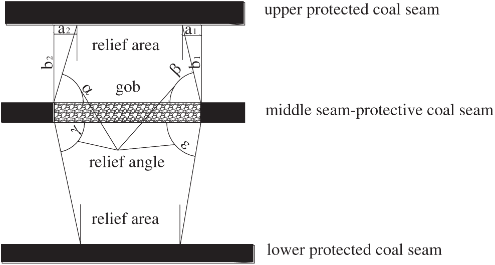
Figure 3: Illustration of the concept of protective coal seam mining effects in the upper and lower coal seams
The pressure relief area is controlled by geology, gas pressure, deformations associated with mining activity, and the vertical stress in PTCS [13]. The outburst-risk in the PTCS is reduced when stress relief occurs in the PTCS [33]. Therefore, this paper adopts stress relief as the protection criteria. The critical stress relief value is given by the following formula, as given in Eq. (2).
where
Selection of the PVCS should meet two conditions: (1) Its excavation should not destroy the ability to mine PTCS (which means the PTCS should be located outside of the caved zone of the PVCS); and (2) It should achieve the best pressure relief effect. Upon excavation of the lower PVCS, the overlying strata may be divided into three relatively distinct zones based on fracture development: the caved zone, the fractured zone, and the continuous deformation zone [34,35]. The height of these three zones [34] can be expressed below in terms of mining height:
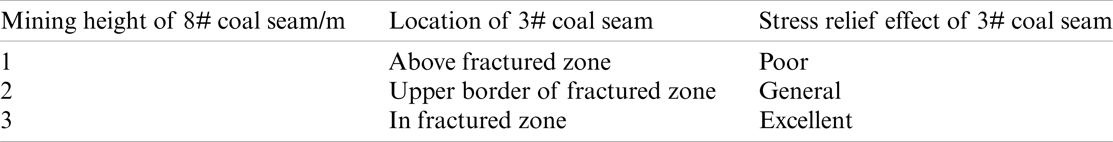
Here Hm is the height of the caved zone, Hd is the height of the fractured zone, and M is the mining height. These formulas were developed based on statistical analysis of a large field database [34]. These are applicable where mining height is less 3 m and overburden strata are of medium strength (like sandstone, argillaceous limestone, sandy shale, mudstone, and sandy mudstone). The different mining heights of the PVCS will affect the stress relief in the PTCS coal seams (Tab. 3).
Table 3: Pressure relief effect in #3 coal seam for different mining heights of #8 coal seam
3.2 Stress Relief and Permeability
Coal and rock mass have naturally-existing geological discontinuities (joints, cracks, and faults). Gas is stored in the pores and fractures mainly in an adsorbed state. The mining of the PVCS increases coal deformations and redistributes stress around adjacent coal and rock mass with stress relief or concentration. The permeability of coal and rock mass in some areas may increase through additional bedding plane fractures and cracks. The gas in both the PTCS and PVCS may desorb and flow into high-permeability regions and the newly formed fracture network [36]. Wang et al. [37] investigated changes in the permeability of sedimentary rocks (mudstone, medium-sandstone etc.) using the confined compression test and related it to their complete stress-strain history (Fig. 4). The results showed that the permeability varied with the strain states. Prior to reaching the peak strength, the permeability decreased with increased loading. However, permeability increased beyond the peak strength during the strain–softening behavior.
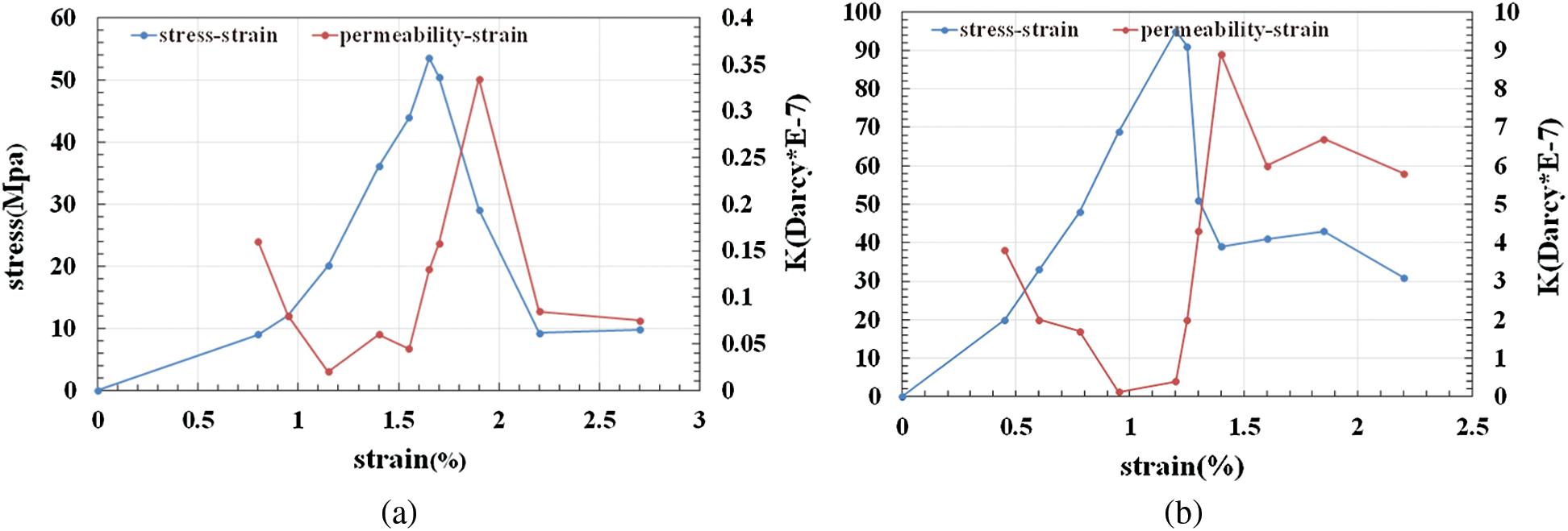
Figure 4: Permeability and complete stress-strain curves for selected rock types under confined compression [37] (a) mudstone (b) medium-grain sandstone
Li et al. [20] studied permeability changes using a stress-based permeability model. The established model for both the fracture and matrix systems was given in Eq. (5):
where K is the bulk modulus of the coal-fracture assemblage mass;
The gas migration rate is related to coal permeability, which is directly determined by the opening and closure of fractures. Therefore, the relationship between stress and permeability can be studied indirectly by studying the relationship between changes in stress, cracks formation and deformation, and rock mass permeability. Fig. 5 illustrates relationship between crack orientation and applied stress. The relationship between normal stress and crack opening can be expressed as follows (Eqs. (6)–(9)) [24,38–41]:
where
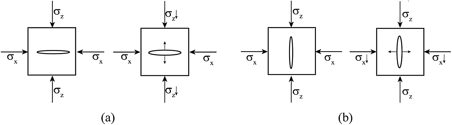
Figure 5: Crack deformation as normal stress decreases (the symbol
The degree of fracture closure is expressed as follows:
The permeability of a single crack is expressed as:
In the above equation,
Permeability can then be expressed in a dimensionless form:
where
4.1 Description of the Numerical Model
Numerical models were developed to simulate rock mass behavior during the mining of the lower PVCS at the study mine [42]. Z-coordinate represents the vertical direction of the model, and X-and Y-coordinates are the two horizontal directions. The boundary conditions for the model were applied: the bottom horizontal boundary is constrained in the Z-direction while the top boundary is free to deform; and the surrounding displacement boundaries are horizontally constrained. The dimensions of the model are
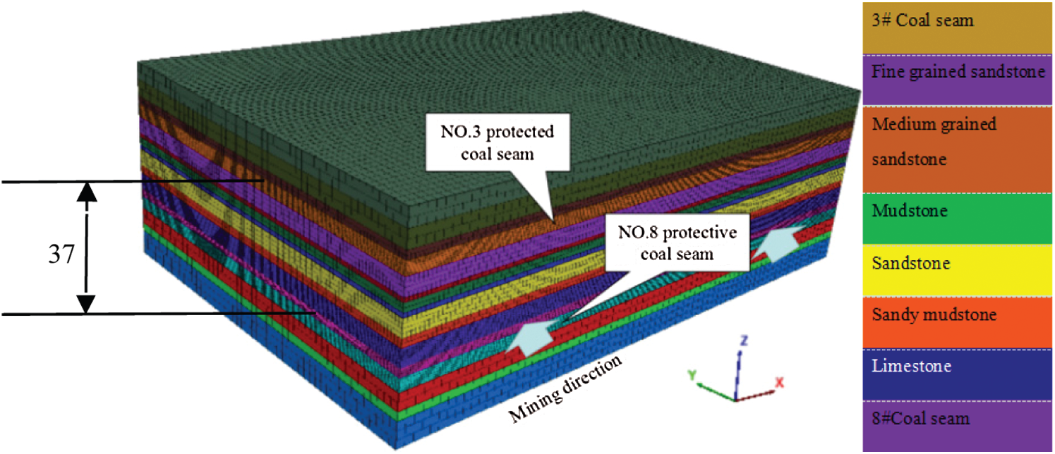
Figure 6: FLAC
The generalized Hoek–Brown criterion (Eqs. (10)–(16)) is expressed as [43]:
where
where s and a are constants for the rock mass, and we have the following relationships:
where D is a factor depending upon the degree of disturbance to which the rock mass has been subjected by blast damage and stress relaxation. It varies from zero for undisturbed subsurface rock mass to one for very disturbed rock masses. D = 0 is assumed in our study.
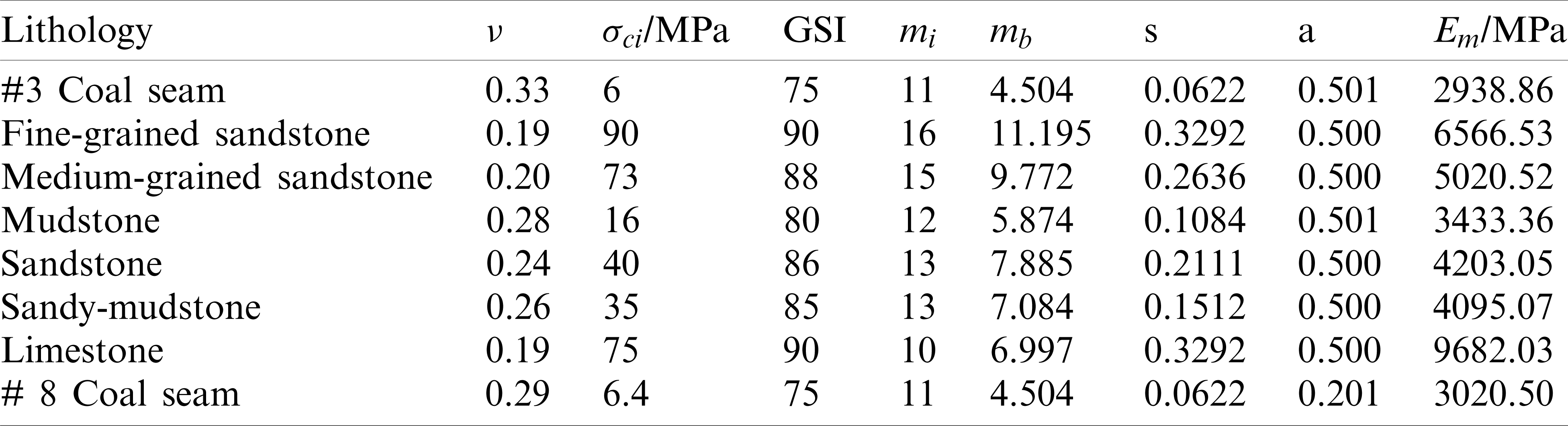
Table 4: Hoek–Brown parameters, GSI and Rock mass properties used in numerical modeling
The estimation of the rock mass strength is:
Two panels of the PVCS (#8 coal seam) are simulated in the FLAC3D model, but only 84306 longwall face is excavated in this study. As shown in Fig. 7, the length and width of the longwall face are 160 and 270 m, respectively. The location of headgate and tailgate entries are shown in Fig. 7a, and a coal pillar with 20 m width is setup between these two gate entries. To improve the calculation speed of the model, only half the width of the longwall face is modeled. A set up room with 7 m width is excavated first from the starting line (20 m from the edge of model). Shields are setup in this area and are advanced with the coal face advance. The face is advanced in increments of 2 m along the Y direction. The stress relief in different locations of the PTCS is analyzed using 12 monitoring lines along the Y-directions at the Z coordinate of 73, which is set up in the #3 coal seam.
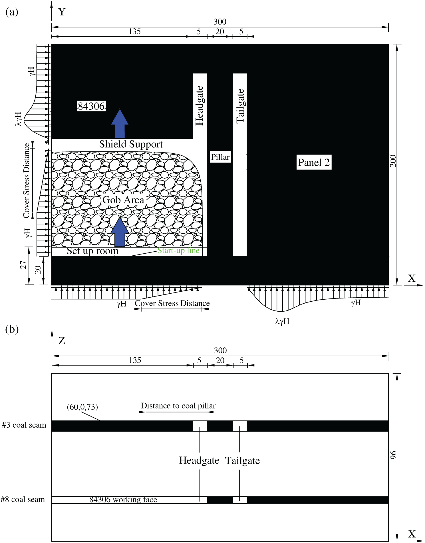
Figure 7: Elevation and plan views of modeled faces. (a) Plan view (b) Elevation view
Fig. 8 shows that the cross section with Z coordinate equals to 73 cuts through the FLAC3D model in the middle of #3 coal seam (Fig. 8a). The distance from the left model edge to the coal pillar is 140 m. Therefore, 12 monitoring lines were established along the cutting plane from
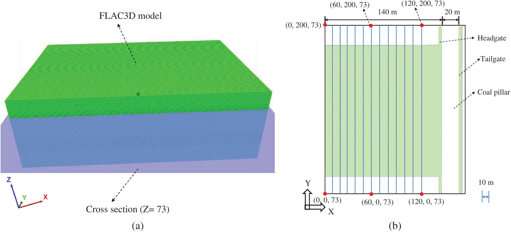
Figure 8: Data monitoring lines layout (a) cross section in FLAC3D model (b) the monitoring lines location
5.1 Stress Redistribution and Stress Relief Coefficients
Vertical stress redistribution and pressure relief coefficient in the PTCS are shown in Figs. 9 and 10 for different face advance positions in #8 coal seam for (60, 0, 73)–(60, 200, 73) monitoring lines.
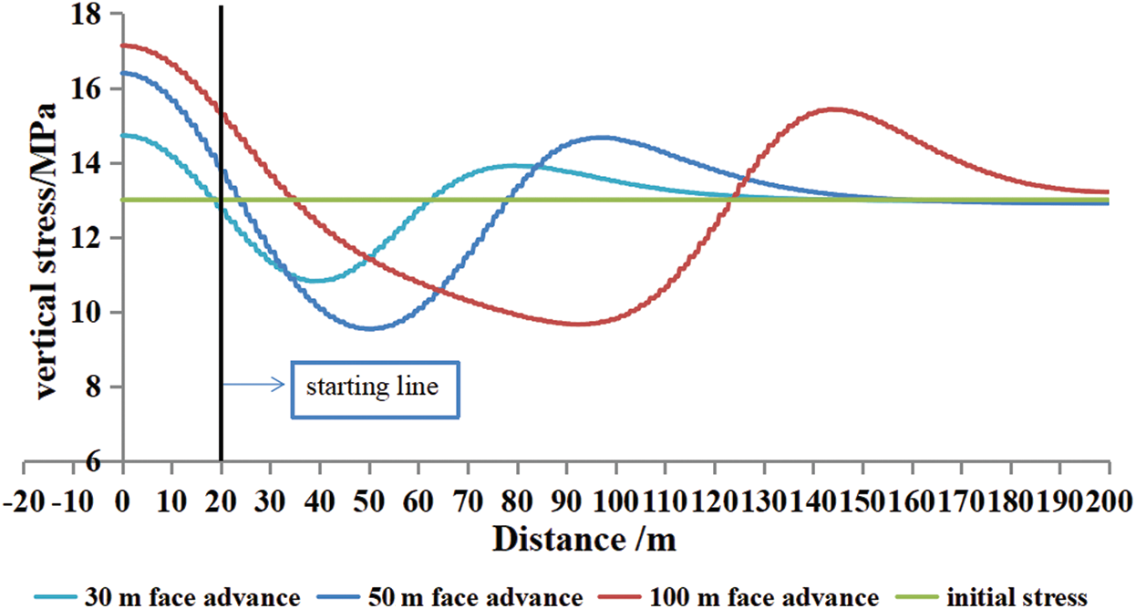
Figure 9: Vertical stress distribution for different face advance values in the PTCS
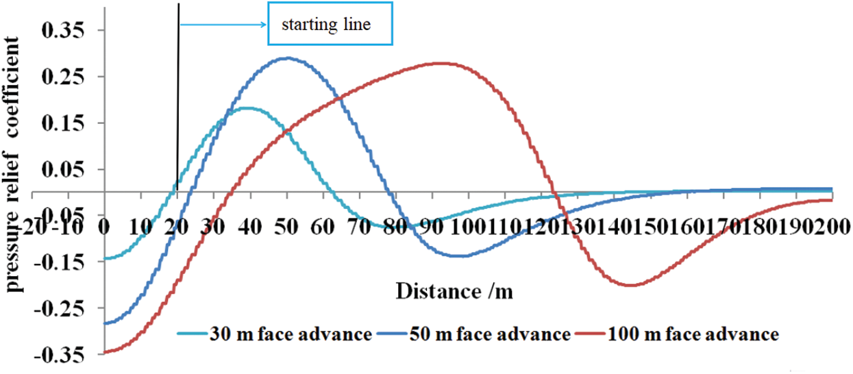
Figure 10: Pressure relief coefficient for different face advance values in the PTCS
1) For 30 m face advance in the PVCS, the minimum vertical stress in the PTCS is located about 18 m behind the coal face. The stress distribution curve in the PTCS is approximately V-shaped, and the maximum pressure relief area is located around the middle of the gob. The vertical stress is about 10.5 MPa, and the pressure relief coefficient is about 0.19. The vertical stress increased ahead of the longwall face and behind in the set up room areas (Figs. 9 and 11). The peak stress values in these regions are 14.5 and 14.9 MPa, respectively, with stress concentration factor values (SCF) of 1.1 and 1.14. Since the immediate roof in the PVCS has not caved, the pressure relief and stress concentrations in the PTCS are relatively small.
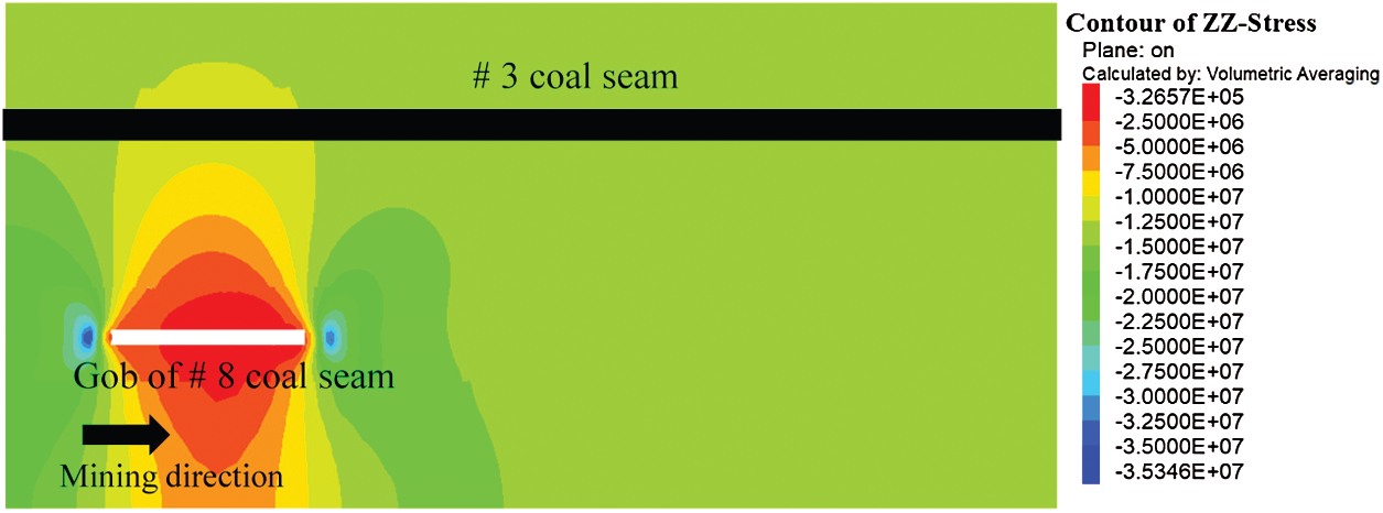
Figure 11: Vertical stress contours along the face advance direction in the PTCS for 30 m PVCS face advance
2) For 50 m face advance in the PVCS (Fig. 12), the minimum vertical stress in the PTCS is about 27 m behind the longwall face with the vertical stress values of about 9.5 MPa, and the stress relief coefficient of 0.28 (Figs. 9 and 12). The V-shape depression extends over a larger area as compared to 30 m face advance. The maximum pressure relief zone is located around the center of the gob about 10 to 30 m behind the working face. The PTCS has lower vertical stresses with a stress relief coefficient of more than 0.15. The peak stress values in the PTCS are 15 and 16.1 MPa around the front of the longwall face and behind the open-off cut area of the PVCS with the SCF values of 1.15 and 1.24. These values are higher than for 30 m face advance. The main roof collapses, and part of the overburden weight is transferred to the coal face and the open mined-out area.
3) For 100 m face advance in the PVCS, the vertical stress contour in the PTCS is shown in Fig. 13. In conjunction with Figs. 9 and 10, it should be noted that the minimum vertical stress in the PTCS is about 35 m behind the coal face. The vertical stress value in the PTCS is about 9.8 MPa, and the stress relief coefficient is about 0.26 similar to face advance of 50 m. The vertical stress in the protected layer is generally U-shaped, and the maximum pressure relief in the protected layer is located on the gob side (Fig. 10). The vertical stress in the PTCS significantly reduces around 15 to 75 m behind the coal face, and the stress relief coefficient increases up to about 0.15. The vertical stress distribution in the PTCS is asymmetrical, and the degree of pressure relief is slightly lower around the peak value area, indicating that the caving rock mass in the gob is gradually compacted with face advance, and its ability to carry more load. The peak stress value in the PTCS both in the face area and mined-out area increases further, reaching values of 16 and 17 MPa with the SCF values of 1.23 and 1.31. The pressure relief angle is calculated using the critical values of stress relief coefficients (Section 3.1). The pressure relief angles around the face and around the back of the mined-out areas are
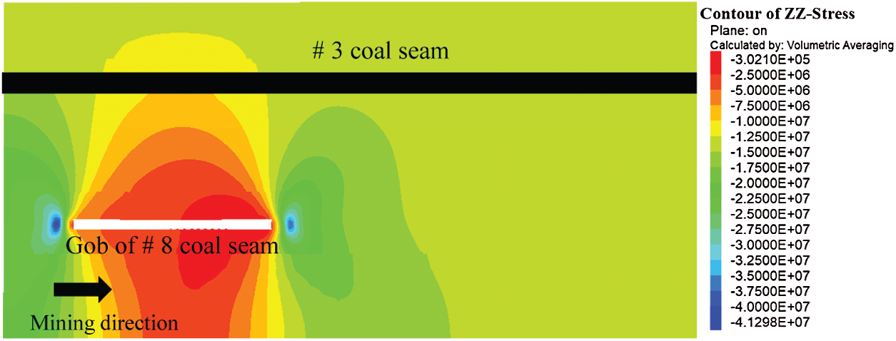
Figure 12: Vertical stress contours along face advance in the PTCS for 50 m PVCS face advance
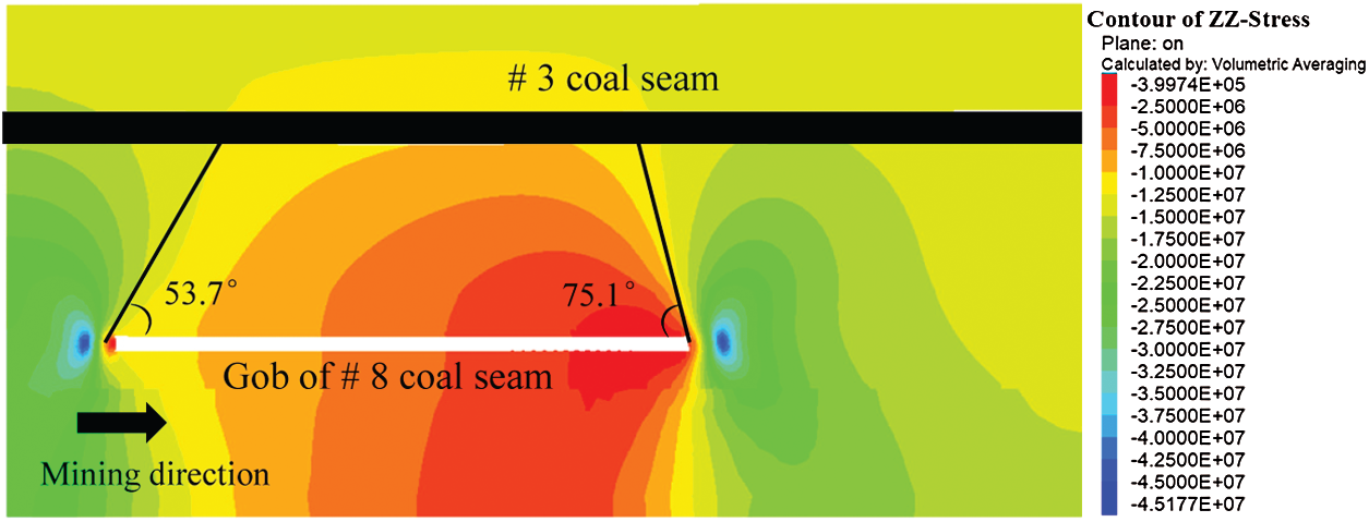
Figure 13: Vertical stress contour along face advance direction of the PTCS for 100 m face advance of the PVCS
In summary, the degree and extent of pressure relief in the PTCS increases gradually with the face advance in the PVCS. With collapse of the immediate roof and main roof behind the face, the overburden stress is transferred ahead of the face and on to the caved gob. With the increase in roof deformation and its vertical movement, the broken rock mass in the gob is gradually compacted, which gradually increases the supporting effect for the main roof, thus reducing to some degree the stress relief of the PVCS in the middle and rear of the gob. Assuming the central axis of the gob as the center line, stress relief around the front of the face and back in the gob area are asymmetrical. Most of pressure relief is concentrated ahead of the face.
The above analyses show that the stress relief degree and extent in the PTCS changes with different face advance distance of the PVCS. The stress relief zone in PTCS for 100 m face advance of PVCS (cutting plane Z-
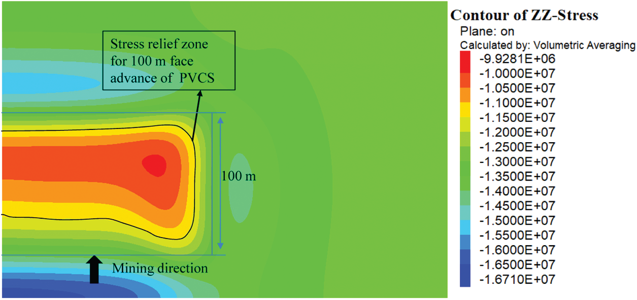
Figure 14: Stress relief zones in the PTCS for 100 m PVCS face advance for Z-
For 100m face advance of PVCS, the vertical stress in the PTCS (Figs. 15 and 16) is gradually reduced, and the pressure relief coefficient increases over a distance from 130 m (X-
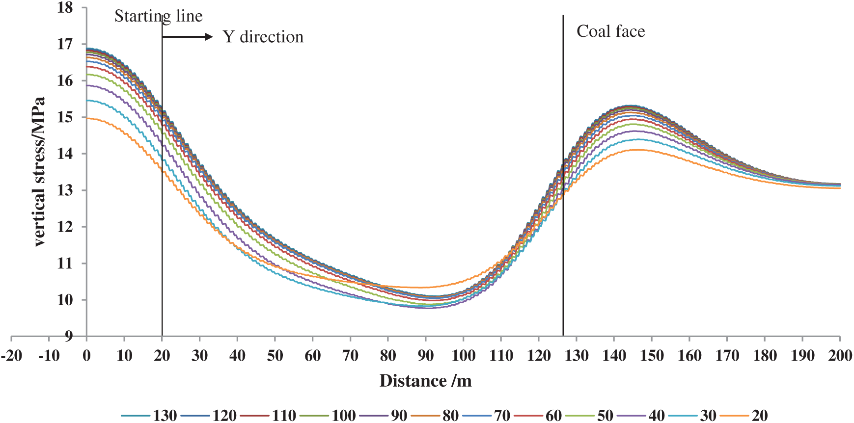
Figure 15: Vertical stress values along x-direction in the PTCS for 100 m face advance in PVCS
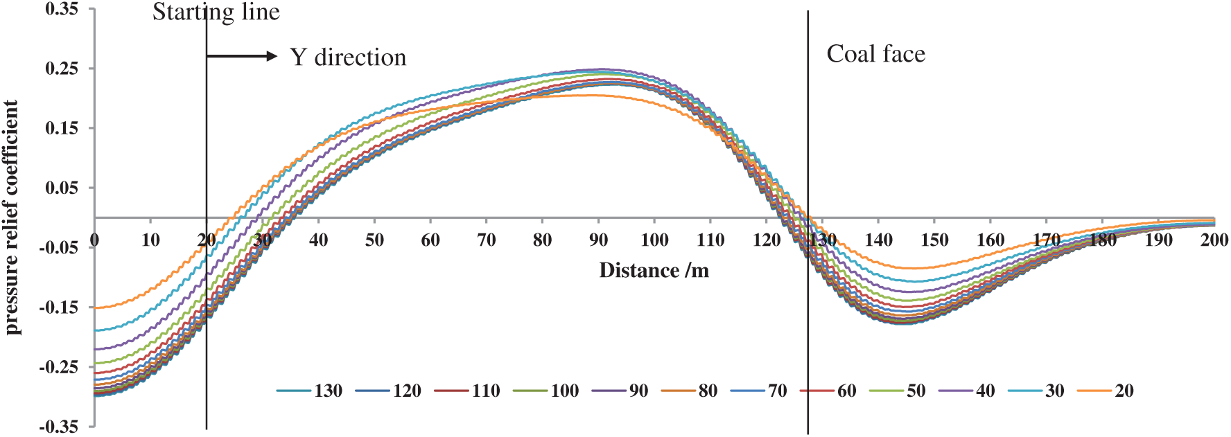
Figure 16: Pressure relief coefficient for different locations in the PTCS along x-direction for 100 m face advance
When the distance from the coal pillar is 130 m which is close to the central axis (X-
When the distance from the coal pillar is 30 m (blue lines in Figs. 15 and 16), the vertical stress in the mined-out and the coal face areas are 15.5 and 14.2 MPa with SCF values of 1.19 and 1.09 with the maximum pressure relief coefficient of about 0.27.
The maximum pressure relief coefficient in the PTCS is similar for different distances away from the coal pillar. However, as the monitoring lines get farther and farther from the coal pillar, the location of the maximum pressure relief coefficient gets closer to the coal face. Therefore, the PTCS goes through several stages along the direction of face advance: Compression, stress relief, and expansion, increased stress relief and expansion, stabilized stress relief and expansion, decrease in stress relief and expansion, compression, and stable stress relief and expansion.
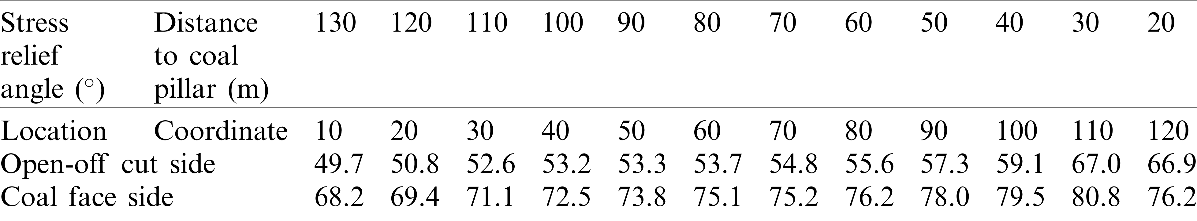
Fig. 16 also shows that the pressure relief angle variation along the direction of the face advance for different distances away from the coal pillar. Tab. 5 includes the pressure relief angle for the pressure relief coefficient of 0.1. Overall, the pressure relief angle in the mined-out area is generally smaller than that ahead of the coal face. As the distance to the pillar decreases, the pressure relief angle on both sides increases first and then decreases, and the maximum value is
Table 5: Relief angle in the PTCS along X-direction
In order to analyze the vertical stress changes along the strike of the PTCS for different positions in the gob during the mining of the PVCS, four cross-section planes were analyzed perpendicular to the Y-axis for different positions behind the face in the gob during the PVCS mining: 100 m (Fig. 17a), 60 m (Fig. 17b), 20 m (Fig. 17c), and −20 m (Fig. 17d). The pressure relief extent was also analyzed when the PVCS is advanced 120 m. With the increase in distance to the working face, the extent and degree of stress relief gradually extend and reach the maximum at about 40 m behind the face. If the distance from the working face decreases further, both the range and the degree of stress relief gradually decrease.
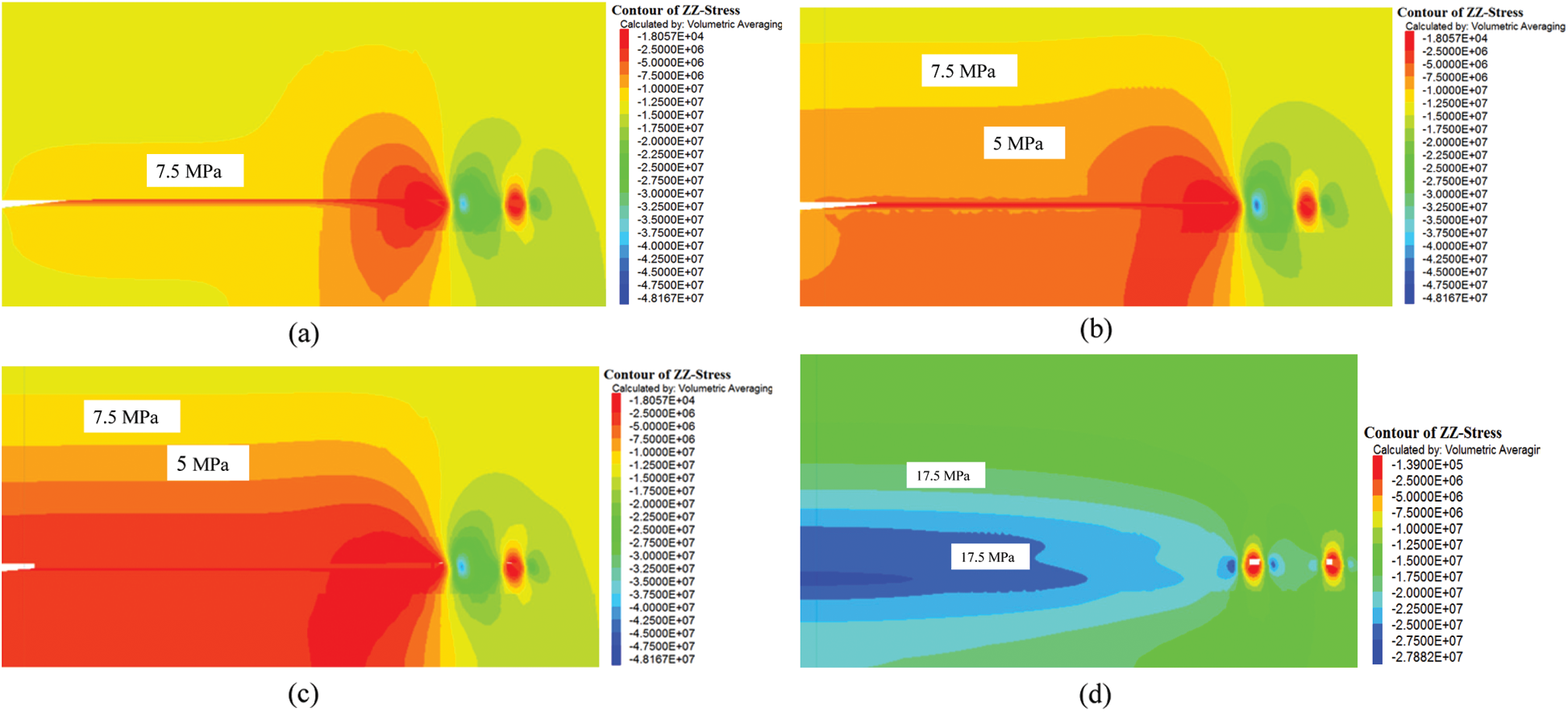
Figure 17: Vertical stress contour along the strike of the PTCS for 120 m face advance of the PVCS 100 m behind the coal face (b) 60 m behind the coal face (c) 20 m behind the coal face (d) 20 m ahead of the coal face
5.2 Effects of Mining Height on Stress Relief
Fig. 18 shows stress relief coefficient in the PTCS for different mining heights as the working face in the PVCS advances. These data are for the data monitoring line (60, 0, 72)–(60, 200, 72).
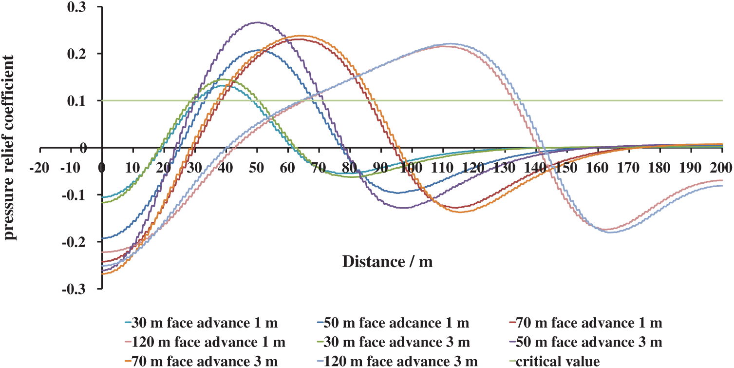
Figure 18: Variation of the stress relief coefficient in the PTCS for different mining heights for different face positions
For 30 m face advance, the stress relief extent and the coefficient are almost the same. The maximum values of the stress relief coefficient for 1 and 3 m mining heights are 0.12 and 0.14. The location center of the relieved area is about 17 m behind the working face.
For 50 m face advance, the above coefficients are 0.21 and 0.28. Similar data for 70 and 120 m face advances vary 0.23 to 0.24. The above results show that the influence of the mining height on the extent and the degree of stress relief in the PTCS vary only in the initial stage of mining.
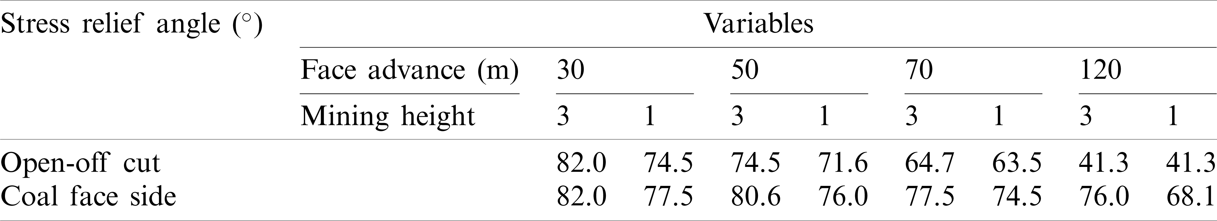
Additional analyses were performed to quantify the influence of the mining height on the stress relief coefficients and stress relief angles along the strike direction (Tab. 6). The stress relief angle for two mining heights decrease with values of
Table 6: Relief angles along strike (Y-coordinate direction) for different mining heights for different face advance
5.3 Effect of the Inter-Burden Lithology between the PVCS and PTCS on Stress Relief
The rock mass properties within the interburden layers affect the stress relief in the PTCS. Rock mass properties of interest include elastic moduli, cohesion, and bulk density. The general consensus is that the disturbance and damage within the overlying strata will increase with the decrease in strength of the inter-burden layers, and that should increase the extent and degree of stress relief. To quantify these effects, three interburden lithologies with engineering properties in Tab. 4 were simulated.
Fig. 19 shows the stress relief coefficients for different interburden lithologies. They decrease with the higher stiffness or elastic modulus of the interburden layers (
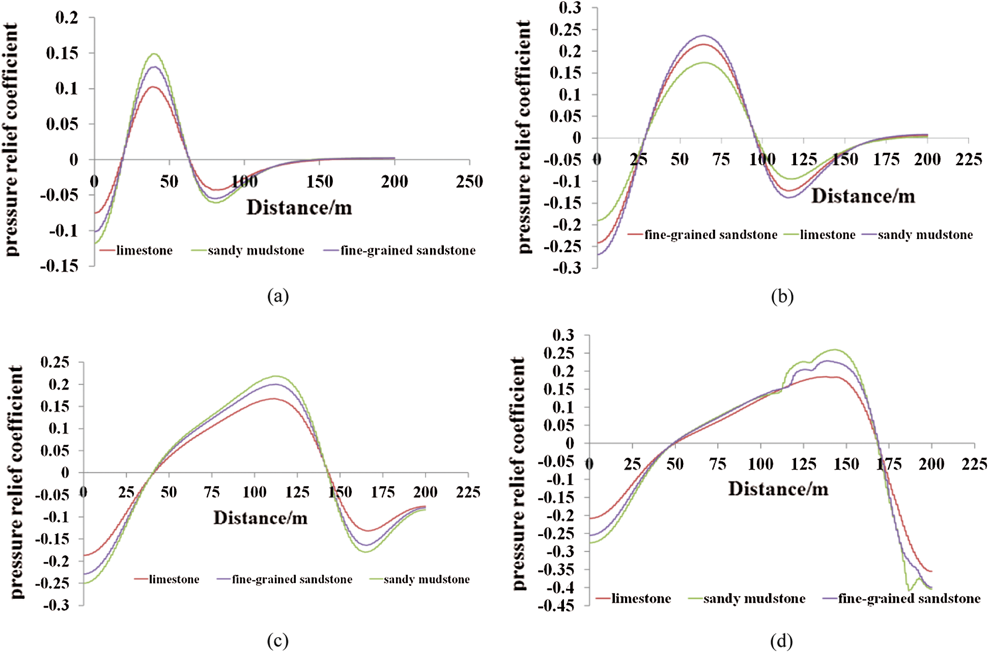
Figure 19: Pressure relief coefficients in the PTCS with different properties of inter-burden rock mass for different face advances of the PVCS (a) 30 m (b) 70 m (c) 120 m (d) 150 m
5.4 Sensitivity Analysis of Selected Variables
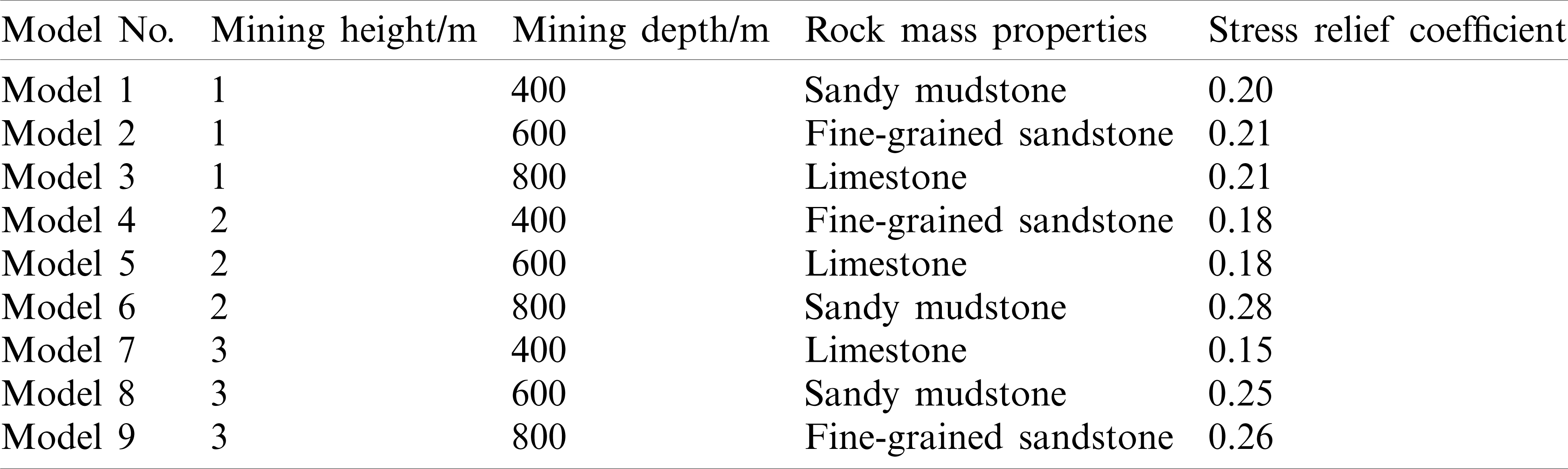
Nine numerical models were run based on the three-level and four-factor orthogonal experiment design without a consideration of interaction among those three factors (Table L9, 34) [44]. The models and results are shown in Tab. 7.
Table 7: Parameters of FLAC3D models for sensitivity analyses
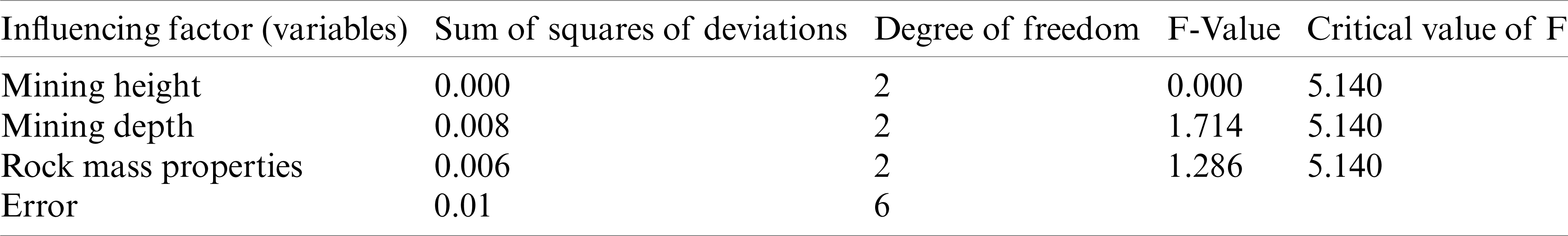
The F value reflects the degree of influence of each factor on the experimental results. It is obtained by the ratio of the squared sum of the mean deviations of the influencing factors to the sum of the squared deviations of the error [44]. Tab. 8 shows the analysis of variance results. The table shows that the order of importance for the selected variables is mining depth, inter-burden lithology, and mining height.
Table 8: Analysis of variance results for selected variables
Mining a PVCS has been widely used to reduce the coal and gas outburst risk where multiple coal seams are present near. This paper has numerically analyzed for a case study mine the progressive effects of this practice on the extent (stress relief angle) and the degree of stress relief as the face in a lower PVCS seam is advanced. The relative importance of mining depth, inter-burden lithology between the two seams, and mining height on the above variables are also analyzed.
(1) With face advance in the PVCS, each point in the protected seam (PTCS) undergoes thru varying stress redistribution in different stages of mining that can be beneficially used from gas drainage point of view. The 3-D shapes of these zones outlined in the results section can aid gas drainage boreholes design.
(2) Both the extent of stress relief and the coefficient of stress relief in the PTCS vary ahead of and behind the face in the mined-out areas. These are affected by the mining face position in relation to caving behind the face in the PVCS.
(3) For this case study, the stress relief angle behind the face in the mined-out area is smaller than ahead of the face. The pressure relief angle along the gob side and the face side increases first and then decreases with face advance to an equilibrium value. The maximum relief angle value is
(4) Mining height affects the stress relief angle during the early stages of mining on the gob side. Ahead of the face, the stress relief angle increases with the mining height.
(5) The pressure relief in the PTCS is affected most by the mining depth, followed by the inter-burden lithology engineering properties and the mining height. The elastic modulus of the inter-burden layers has the most effect on the stress relief in the PTCS among considered engineering properties.
Acknowledgement: The authors would also like to express special thanks to the editor and anonymous reviewers for their professional and constructive suggestion.
Funding Statement: This paper was supported by the Natural Science Foundation of Jiangsu Higher Education Institutions (No. 20KJB440002), the National Natural Science Foundation of China (Project Nos. 51804129, 51808246 and 51904112), China Postdoctoral Science Foundation (No. 2020M671301), the Postdoctoral Science Foundation of Jiangsu Province (Nos. 2019K139 and 2019Z107), the Huai’an Science and Technology Plan project (No. HAB201836), the Industry Education Research Cooperation Projects in Jiangsu Province (No. BY2020007), Undergraduate Innovation and Entrepreneurship Training Program (No. 202011049111XJ) and the Foundation of Huaiyin Institute of Technology (No. Z301B20530).
Conflicts of Interest: The authors declare that they have no conflicts of interest in reporting the present study.
1. National Coal Mine Safety Administration. (2007). Safety regulations for coal mines. China: China Coal Industry Publishing House. [Google Scholar]
2. Wang, F., Zhang, C., Liang, N. (2017). Gas permeability evolution mechanism and comprehensive gas drainage technology for thin coal seam mining. Energies, 10(9), 1382. DOI 10.3390/en10091382. [Google Scholar] [CrossRef]
3. Zou, Q. L., Lin, B. Q., Liu, T., Zhou, Y., Zhang, Z. et al. (2014). Variation of methane adsorption property of coal after the treatment of hydraulic slotting and methane pre-drainage: A case study. Journal of Natural Gas Science and Engineering, 20, 396–406. DOI 10.1016/j.jngse.2014.07.024. [Google Scholar] [CrossRef]
4. Zhang, C. L. (2017). Fracture development and stress relief with space influenced by mining of coal seams group (Ph.D. Thesis). China University of Mining and Technology, Beijing. [Google Scholar]
5. Cheng, C., Ren, Y. P., Wang, T., Kong, L., Lu, S. L. et al. (2014). Gas ejection accident analysis in bed splitting under igneous sills and the associated control technologies: A case study in the Yangliu Mine, Huaibei Coalfield. China Natural Hazards, 71(1), 109–134. DOI 10.1007/s11069-013-0903-8. [Google Scholar] [CrossRef]
6. Li, Q., Lin, B., Zhai, C. (2015). A new technique for preventing and controlling coal and gas outburst hazard with pulse hydraulic fracturing: A case study in Yuwu coal mine. China Natural Hazards, 75(3), 2931–2946. DOI 10.1007/s11069-014-1469-9. [Google Scholar] [CrossRef]
7. Zhang, C., Tu, S. H., Bai, Q. S., Yang, G. Y., Zhang, L. (2015). Evaluating pressure-relief mining performances based on surface gas venthole extraction data in longwall coal mines. Journal of Natural Gas Science and Engineering, 24, 431–440. DOI 10.1016/j.jngse.2015.04.012. [Google Scholar] [CrossRef]
8. Somerton, W. H., Söylemezoglu, I. M., Dudley, R. C. (1975). Effect of stress on permeability of coal. International Journal of Rock Mechanics and Mining Sciences & Geomechanics Abstracts, 12, 129–145. DOI 10.1016/0148-9062(75)91244-9. [Google Scholar] [CrossRef]
9. McKee, C. R., Bumb, A. C., Koenig, R. A. (1988). Stress-dependent permeability and porosity of coal and other geologic formations. SPE Formation Evaluation, 3(1), 81–91. DOI 10.2118/15227-PA. [Google Scholar] [CrossRef]
10. Enever, J. R. E., Henning, A. (1997). The relationship between permeability and effective stress for Australian coal and its implications with respect to coalbed methane exploration and reservoir model. Proceedings of the International Coalbed Methane Symposium, pp. 12–17. Tuscaloosa, AL, USA. University of Alabama. [Google Scholar]
11. Lowndes, I. S., Reddis, D. J., Ren, T. X., Whittles, H. D. M. (2002). Mine Ventilation. Proceedings of the North American/Ninth US Mine Ventilation Symposium, pp. 267–272. Boca Raton, FL, USA. CRC Press. [Google Scholar]
12. Esterhuizen, G. S., Karacan, C. Ö. (2005). Development of numerical models to investigate permeability changes and gas emission around longwall mining panel. Proceedings of the 40th U.S. Rock Mechanics Symposium, pp. 25–29. Anchorage, AK, USA. [Google Scholar]
13. Zhang, C. L., Yu, L., Feng, R., Zhang, Y., Zhang, G. (2018). Numerical study of stress distribution and fracture development above a protective coal seam in longwall mining. Processes, 6(9), 146. DOI 10.3390/pr6090146. [Google Scholar] [CrossRef]
14. Zhang, C. L., Zhang, Y. (2016). Stress and fracture evolution based on abutment change in thick coal seam—A case study in China colliery. Electronic Journal of Geotechnical Engineering, 21, 4369–4386. http://www.ejge.com/2016/Ppr2016.0374ma.pdf. [Google Scholar]
15. Zhou, H. X., Zhang, R., Cheng, Y. P., Dai, H., Ge, C. G. (2015). Methane and coal exploitation strategy of highly outburst-prone coal seam configurations. Journal of Natural Gas Science and Engineering, 23, 63–69. DOI 10.1016/j.jngse.2015.01.042. [Google Scholar] [CrossRef]
16. Morsy, K., Peng, S. S. (2002). Numerical modeling of the gob loading mechanism in longwall coal mines. 21st International Conference on Ground Control in Mining, pp. 58–67. Morgantown, WV. [Google Scholar]
17. Yavuz, H. (2004). An estimation method for cover pressure re-establishment distance and pressure distribution in the goaf of longwall coal mines. International Journal of Rock Mechanics & Mining Science, 41(2), 193–205. DOI 10.1016/S1365-1609(03)00082-0. [Google Scholar] [CrossRef]
18. Esterhuizen, E., Mark, C., Murphy, M. M. (2010). Numerical model calibration for simulating coal pillars, gob and overburden response. Proceedings of the 29th International Conference on Ground Control in Mining, pp. 46–57. Morgantown, WV, USA. [Google Scholar]
19. Suchowerska, A. M., Merifield, R. S., Carter, J. P. (2013). Vertical stress changes in multi-seam mining under supercritical longwall panels. International Journal of Rock Mechanics & Mining Sciences, 61, 306–320. DOI 10.1016/j.ijrmms.2013.02.009. [Google Scholar] [CrossRef]
20. Li, W., Cheng, Y. P., Guo, P. K., An, F. H., Chen, M. Y. (2014). The evolution of permeability and gas composition during remote protective longwall mining and stress-relief gas drainage: A case study of the underground Haishiwan Coal Mine. Geosciences Journal, 18(4), 427–437. DOI 10.1007/s12303-014-0013-y. [Google Scholar] [CrossRef]
21. Zhang, Y., Zhang, X. B., Xu, L. F., Zhang, J. L., Zhou, G. L. (2012). Formation and evolution of gas flow channels in the abutment pressure area. International Journal of Mining Science and Technology, 22(6), 801–807. DOI 10.1016/j.ijmst.2012.12.014. [Google Scholar] [CrossRef]
22. Hu, G. Z., Wang, H. T., Li, X. H., Fan, X. G., Yuan, Z. G. (2009). Numerical simulation of protection range in exploiting the upper protective layer with a bow pseudo-incline technique. Mining Science and Technology, 19, 58–64. DOI 10.1016/S1674-5264(09)60011-9. [Google Scholar] [CrossRef]
23. Liu, Y. K., Zhou, F. B., Liu, L., Liu, C., Hu, S. Y. (2011). An experimental and numerical investigation on the deformation of overlying coal seams above double-seam extraction for controlling coal mine methane emissions. International Journal of Coal Geology, 87(2), 139–149. DOI 10.1016/j.coal.2011.06.003. [Google Scholar] [CrossRef]
24. Yang, W., Liu, B. Q., Qu, Y. A., Zhao, S., Zhai, C. et al. (2011). Mechanism of strata deformation under protective seam and its application for relieved methane control. International Journal of Coal Geology, 85(3–4), 300–306. DOI 10.1016/j.coal.2010.12.008. [Google Scholar] [CrossRef]
25. Yang, W., Lin, W., Qu, B. Q., Zhao, Y. A., Zhai, S. et al. (2011). Stress evolution with time and space during mining of a coal seam. International Journal of Rock Mechanics & Mining Sciences, 48(7), 1145–1152. DOI 10.1016/j.ijrmms.2011.07.006. [Google Scholar] [CrossRef]
26. Huang, X. C., Sun, D. L., Feng, K. W. (2015). An analysis on the effect of mining height and floor lithology on pressure relief of upper protective layers. Journal of Coal Science and Engineering (China), 19(1), 46–50. DOI 10.1007/s12404-013-0108-5. [Google Scholar] [CrossRef]
27. Yang, K., He, K., Dou, X., Liu, L. T., Sun, W. J. et al. (2015). Experimental investigation into stress-relief characteristics with upward large height and upward mining under hard thick roof. International Journal of Coal Science and Technology, 2(1), 91–96. DOI 10.1007/s40789-015-0066-1. [Google Scholar] [CrossRef]
28. Liu, Z., Yang, H., Cheng, W., Xin, L., Ni, G. (2017). Stress distribution characteristic analysis and control of coal and gas outburst disaster in a pressure-relief boundary area in protective layer mining. Arabian Journal of Geosciences, 10(16), 358. DOI 10.1007/s12517-017-3149-z. [Google Scholar] [CrossRef]
29. Cao, Z. Y., He, X., Wang, E., Kong, B. (2018). Protection scope and gas extraction of the low-protective layer in a thin coal seam: Lessons from the DaHe coalfield. China Geosciences Journal, 22(3), 487–499. DOI 10.1007/s12303-017-0061-1. [Google Scholar] [CrossRef]
30. Cheng, X., Zhao, X., Li, G. M., Meng, Y. M., Dong, X. R. et al. (2018). Researches of fracture evolution induced by soft rock protective seam mining and an omni-directional stereo pressure-relief gas extraction technical system: A case study. Arabian Journal of Geosciences, 11(12), 326. DOI 10.1007/s12517-018-3666-4. [Google Scholar] [CrossRef]
31. Yuan, Y., Chen, Z. S., Yuan, C. F., Zhu, C., Wei, H. M. et al. (2020). Numerical simulation analysis of the permeability enhancement and pressure relief of auger mining. Natural Resources Research, 29(1), 931–948. DOI 10.1007/s11053-019-09589-z. [Google Scholar] [CrossRef]
32. Karacan, C. Ö., Goodman, G. (2009). Hydraulic conductivity changes and influencing factors in longwall overburden determined by slug tests in gob gas ventholes. International Journal of Rock Mechanics & Mining Sciences, 46(7), 1162–1174. DOI 10.1016/j.ijrmms.2009.02.005. [Google Scholar] [CrossRef]
33.  ,
,  ,
,  ,
,  ,
,  ,
,  (2004). Forecast method and preventing measure of coal and gas burst. China: China Coal Industry Publishing House. [Google Scholar]
34. Qian, M. G., Shi, P. W. (2003). Ground pressure and strata control. China: The Press of China University of Mining and Technology. [Google Scholar]
35. Zhang, C. L. (2019). The height and scope of overburden fractured zone of thick coal seam based on different gob behavior for a case coal mine in China. Geotechnical and Geological Engineering, 37, 3299–3311. DOI 10.1007/s10706-019-00845-w. [Google Scholar] [CrossRef]
36. Moore, T. A. (2012). Coalbed methane: A review. International Journal of Coal Geology, 101, 36–81. DOI 10.1016/j.coal.2012.05.011. [Google Scholar] [CrossRef]
37. Wang, J. A., Park, H. D. (2002). Fluid permeability of sedimentary rocks in a complete stress-strain process. Engineering Geology, 63(3), 291–300. DOI 10.1016/S0013-7952(01)00088-6. [Google Scholar] [CrossRef]
38. Baghbanan, A., Jing, L. (2008). Stress effects on permeability in a fractured rock mass with correlated fracture length and aperture. International Journal of Rock Mechanics & Mining Sciences, 45(8), 1320–1334. DOI 10.1016/j.ijrmms.2008.01.015. [Google Scholar] [CrossRef]
39. Bandis, S. C., Lumsden, A. C., Barton, N. R. (1983). Fundamentals of rock joint deformation. International Journal of Rock Mechanics and Mining Sciences & Geomechanics Abstracts, 20(6), 249–268. DOI 10.1016/0148-9062(83)90595-8. [Google Scholar] [CrossRef]
40. Goodman, R. E. (1976). Methods of geological engineering in discontinuous rocks. New York: West Publishing. [Google Scholar]
41. Min, K. B., Rutqvist, J., Tsang, C. F., Jing, L. (2004). Stress-dependent permeability of fractured rock masses: A numerical study. International Journal of Rock Mechanics & Mining Sciences, 41(7), 1191–1210. DOI 10.1016/j.ijrmms.2004.05.005. [Google Scholar] [CrossRef]
42. Itasca Consulting Group, Inc. (2017). FLAC3D user’s guide. [Google Scholar]
43. Hoek, E., Carranza-Torres, C., Corkum, B. (2002). Hoek-Brown failure criterion—2002 edition. Proceedings of the 5th North American Rock Mechanics Symposium and the 17th Tunneling Association of Canada Conference, pp. 267–273. Toronto, ON, Canada. [Google Scholar]
44. Liu, W. T., Liu, S. L., Ji, B. J. (2015). Sensitivity analysis of controlling factors on failure depth of floor based on orthogonal experiment. Journal of China Coal Society, 40(9), 1995–2001, (In Chinese). DOI 10.13225/j.cnki.jccs.2014.1682. [Google Scholar] [CrossRef]
 | This work is licensed under a Creative Commons Attribution 4.0 International License, which permits unrestricted use, distribution, and reproduction in any medium, provided the original work is properly cited. |