DOI: 10.32604/cmes.2021.013478
ARTICLE
Fabrication and Statics Performance of Pyramidal Lattice Stitched Foam Sandwich Composites
Department of Engineering Mechanics, Harbin University of Science and Technology, Harbin, China
*Corresponding Author: Shi Yan. Email: yanshi@hrbust.edu.cn
Received: 07 August 2020; Accepted: 29 October 2020
Abstract: In this study, the pyramidal lattice stitched foam sandwich composite materials were manufactured by integrating top and bottom panels with pyramidal lattice core to overcome the weak interface between the core and the skins of the sandwich structure. The influence of the reinforcing core rods on the mechanical properties including compressive, shear, and three-point bending performances of the foam sandwich composite materials were revealed through theoretical analysis and comparative experiments. The theoretical predictions were consistent with the experimental results. Compressive test, shear test and three-point bending test were performed. The experimental results show that the core rods can significantly improve the compressive performance and energy absorption efficiency of the pyramidal lattice stitched foam sandwich structure. The effect is related to the diameter of the core rod. The core rod with large diameter has better effect. Compared with the foam sandwich structure, the pyramidal lattice reinforcing foam composites have stronger shear and bending resistance. The failure modes and failure mechanisms of the pyramidal lattice stitched foam sandwich structure under the shear load are given. The failure modes and failure mechanisms of the pyramidal lattice stitched foam sandwich structure under the three-point bending load are also given. The study concludes that compared with the foam sandwich structure, the overall mechanical properties of the lattice stitched foam sandwich structure composites are significantly improved.
Keywords: Pyramidal lattice; compressive performance; shear; three-point bending; failure modes
Sandwich structure composite materials which have the advantages of high strength and lightweight have attracted much attention, especially in the aerospace industry [1–4]. In recent years, the traditional sandwich structure composite materials such as foam sandwich structure and honeycomb sandwich structure can no longer meet the higher requirements in some fields, as well as the research intensity of the lattice stitched form sandwich structure composite materials with lightweight, higher specific strength and specific rigidity is gradually increasing [5–12].
Researchers have proposed several methods for preparing the lattice sandwich structure composites, because of the wide range of application prospects, such as hot press molding, weaving and sheet folding [13–15]. Also, the preparation process of the metal lattice sandwich structure mainly includes the stamping and folding brazing method [16–18], the pultrusion discharge method and the insert assembly method [19]. Here, we only introduce the relevant content of the composite material preparation method [20].
Kevin [21] used a water jet cutting machine to cut the composite laminate along the fiber into the corrugated slender strut cores and then the strut cores were assembled with the face sheets to manufacture the structure. Xu et al. [22] used hot press molding to manufacture composite sandwich beams with lattice core. The author put strut cores made up of carbon fiber prepreg and the top and bottom face sheets into the rigid mold and then the specimen was vacuum-bagged and cured in an autoclave at 135 degrees under the pressure of 0.5 MPa for 120 min. Wang et al. [23,24] manufactured foam sandwich structures that were reinforced by carbon fiber columns.
The static mechanical state refers to the long-term load of the sandwich structure composite material which is an important reference for evaluating the preparation process and improving the structure, so it is necessary to conduct static mechanics research on the sandwich structure. Rajkumar [25] conducted research and finite element analysis about the characteristics of A3003 aluminum honeycomb core sandwich panels and gave theoretical derivation formulas for various mechanical properties. Chen et al. [26] made a study on mechanical properties of foam sandwich with chopped-glass-fiber/carbon nanotube reinforcing hierarchical structure interlayer. It showed the procedure for the preparation of epoxy/glass fiber-PVC foam sandwich composites and conducted a three-point bending test. Compared with the unreinforced specimen, the result showed that the interfacial chopped fibers increased the overall bearing capacity of the sandwich structure and the ultimate load and bending strength were obviously strengthened. Wang et al. [27] proposed a new type of sandwich construction with the metal rubber-filled corrugated hybrid core (MR-CHC) which consisted of filling the trapezoidal metal rubber materials into the interstices of corrugation. The quasi-static out-of-plane compressive experiments were carried out to study the stiffness and energy absorption ability of the sandwich construction. It demonstrated that the compressive stiffness, the compressive strength and the energy absorption ability of MR-CHC composite structure were higher than those of empty corrugated core sandwich structure as well as single metal rubber material, and increased with the increasing relative density of metal rubber (MR). Lee et al. [28] conducted theoretical analysis and experimental tests on sandwich panels with different layers, analyzed the failure modes and theoretical predictions under different layers and carried out the three-point bending and shear load experiments respectively to analyze the mechanical properties of the structure. Rejab et al. [29] did a plane compression experiment on corrugated sandwich panels, compared the failure modes of corrugated cores with different thicknesses, and made theoretical predictions using finite elements.
In this research, the study aims to demonstrate a new preparation process for using the high-strength carbon fiber strut to reinforce the low-modulus and lightweight foam sandwich structure composite materials to improve the mechanical properties of the pyramidal lattice stitched foam sandwich structure materials and prepare the samples according to the test standards. Then this study compares the compressive resistance of the lattice stitched foam sandwich structure with that of the foam sandwich structure to evaluate the contribution of the lattice core to the compressive performance and energy absorption characteristics. In addition, through shear and three-point bending experiments, the good reinforcing effect of lattice core is analyzed. According to the homogenization theory, the research gives the stiffness and strength of the structure under different loads. Furthermore the research analyzes the failure modes of the two structures under different loads and gives the reasons. The theoretical prediction of the pyramidal lattice stitched foam sandwich structure is also given.
2 Preparation of Pyramidal Lattice Stitched Foam Sandwich Structure
This part mainly introduces various parameters of the specimen materials and specimen preparation technology.
Carbon fiber reinforced by epoxy resin is used to manufacture the pyramidal lattice stitched foam sandwich structure composite materials. The upper and lower panels are made of sixteen layers of unidirectional carbon/epoxy prepreg (T700/TDE85, China Carbon Technology Co., Ltd., China). The stacking sequence is [0 /90
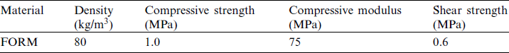
/90 ] s. The experimental parameters of carbon fiber composite materials are shown in Tab. 1 and the mechanical properties of the T700/TDE85 composite materials are shown in Tab. 2. The foam is made of ArmaFORM PET (Armacell International GmbH, China) and the experimental parameters are listed in Tab. 3.
Table 1: The experimental parameters of carbon fiber composite materials
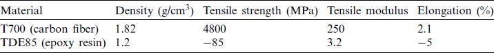
Table 2: Mechanical properties of T700/TDE85 composite materials
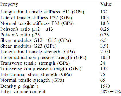
Table 3: The experimental parameters of ArmaFORM PET
Firstly, two 8-layer unidirectional carbon/epoxy prepreg laminates with the holes of which the diameter is 2 mm are fabricated as the top face sheet and the bottom face sheet, the distribution of the holes on one panel is  and the distribution of the holes on the other panel is
  as well as the spacing between every two adjacent holes is 12.25 mm. The thickness of each laminate is 1 mm and the stacking sequence of the laminates is
  . Secondly, the size of the foam is
  , then the foam is fixed on the mold and the foam core with holes is made according to the position of the holes in the top and bottom panels by a hot steel needle piercing through the foam. The foam core and face sheets are stitched together by passing continuous carbon fiber through the holes. Thirdly, the 8-layer carbon/epoxy prepreg laminates with the stacking sequence
  are used to cover the surface of the semi-finished structure. At last, the specimen is placed in a vacuum bag to seal and vacuum. the specimen is kept in a vacuum tank at 135 degrees Celsius for 2.5 h. In this part, the above process is used to prepare specimens for compressive, shear and three-point bending experiments. The flow chart of the preparation process is shown in Fig. 1.

Figure 1: The process for the fabrication of the pyramidal lattice stitched foam sandwich structure
3 Compressive Mechanical Properties
This part introduces the theoretical prediction and experimental process of the specimen under the plane pressure load and compares the results to analyze the effect of the lattice core.
According to the studied specimen model and preparation process, it can be known that the lattice sandwich structure contains a lot of periodically repeated unit cells. Therefore, the homogenization theory is more applicable. In the case of small deformation [5], the deformation of the face sheets has little effect on the geometry of a single cell. The face sheets are regarded as rigid objects. The connection between the fiber rod and the face sheets is regarded as a fixed connection. Therefore, the equivalent rigidity tensor of the pyramidal lattice stitched foam sandwich structure CH is as follows:
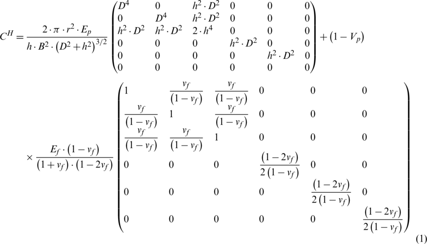
D is the projected length of the carbon fiber rod on the bottom of the lattice;
B is the length of the lattice;
r is the radius of the carbon fiber core rod;
H is the thickness of the core;
Vp is the volume content of the fiber core rod in the crystal lattice;
Ep is the modulus of elasticity of the carbon fiber rod;
Ef is the elastic modulus of the foam;
 is the Poisson’s ratio of the foam;
The formula of  is obtained by the equivalent structural stiffness tensor:

A unit cell contains four core rods. The volume content of the core rod in the unit cell is Vp:

 is the rigidity of the pyramidal lattice stitched foam sandwich structure in the thickness direction The compression modulus of the pyramidal lattice stitched foam sandwich structure in the thickness direction is equal to the reciprocal of Szz in the equivalent flexibility matrix. The expression of the compression modulus is Ec:

In the formula, the left term coefficient of  is composed of the Poisson’s ratio of the structure. The calculated value of
  is 0.74. In the formula, the ideal value is substituted into the calculation and there must be several inevitable errors in the experiment, so the theoretical predicted value is higher than the experimental value generally.
To predict the compressive strength of the structure, the elastic stability theory is used to solve the problem and modify the calculated results. Under the compressive load, the four core rods in the unit cell are subjected to the same force, so one of them is chosen as the object. Under compressive load, the compressive load is transmitted along the path from the panel to the fiber core rod and then to the panel. The fiber core rod is subject to the reaction force of the elastic foam due to deformation. Therefore, the compressive load on the core rod can be decomposed into radial load named p2 and axial load named p1. Force analysis is shown in Fig. 2.
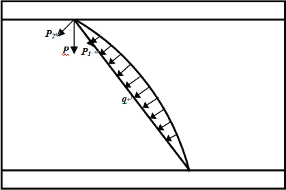
Figure 2: The load state of the fiber core rod under compressive force
In the lattice stitched foam sandwich structure, the core rod is an Euler rod. When p1 reaches the critical load of buckling, the core rod has lateral buckling failure; at this time, p2 makes the core rod rotate slightly at the end, so the connection between the core rod and the panel is not fully hinged or fixed. Therefore, the finite constraints at the end must be considered to obtain a more realistic result when the core rods have buckling failure. Tmoshenko’s [30], Zheng et al. [31] formula is modified as follows:

Ep is the elastic modulus of the core rod;
lp is the moment of inertia of the core rod;
Ip is the length of the core rod;
m is the half wave number of buckling of the core rod  ;
;
 is the Foam Elastic Foundation Modulus;
 is the correction factor of the end constraint of the core rod;
Different values of  correspond to different connection forms. In this paper, let
  .89 based on previous experience. According to material mechanics, when the force of the core rod is p1, the internal stress of the foam is
  ,:
,:

The foam fails before the buckling failure of the core rods, at this time  . Therefore, the compressive strength of the pyramidal lattice stitched foam sandwich structure is
  :
:

Ac is the compression area of the pyramidal lattice stitched foam sandwich structure;
n is the number of carbon fiber core rods;
 is the yield strength of the foam;
Foam elastic foundation modulus  represents the basic reaction force in per unit length of the fiber rod based on the elastic foam under the unit lateral deformation. The schematic diagram of the method of testing is shown in Fig. 3. The load-displacement curve should be recorded.

 is the slope of the straight line in the load-displacement curve.

Figure 3: Determination of the modulus of elasticity of foundation
According to the standard test methods ASTM C-365, innstron3382 universal testing machine is used to run the compressive tests of lattice stitched foam sandwich structure and the foam sandwich structure. There are three kinds of samples including the unreinforced foam sandwich structure, the lattice stitched foam sandwich structure with the toughened core rods of which the diameter is 1 mm and the lattice stitched foam sandwich structure with the toughened core rods of which the diameter is 1.4 mm in this experiment [32]. The form of displacement loading is adopted; the loading rate is 0.5 mm/min. The test equipment is shown in Fig. 4.
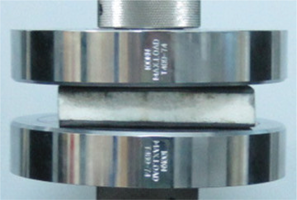
Figure 4: The equipment of the compressive tests
Compressive stress:

 is the flat compressive stress of the sandwich structure, unit: MPa;
 is the compressive load measured by the testing machine, unit: N;
 is the effective load-bearing cross-sectional area in the sandwich structure, unit:
  ;
;
Plane compressive strain:

 is the flat compressive strain of the sandwich structure
 is the compressive displacement measured by the testing machine, unit: mm;
 is the height of the core of the sandwich structure, unit: mm;
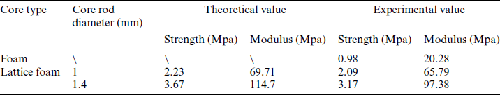
The compressive stress–strain curves of the plane compressive experiment are shown in Fig. 5. The theoretical analysis and the experimental results are shown in Tab. 4. Yield deformation begins to occur after compressive strain exceeds 5%. It can be known that the foam sandwich structure has the strength of only 0.98 MPa and the modulus of 20.28 MPa (in Tab. 4). The foam begins to yield when the foam sandwich structure carries a force of about 10,000 N. It keeps the state until the foam is compacted due to the porous nature of the foam material. However, the strength and the modulus of the foam sandwich structure toughened with the 1 mm diameter core rods are significantly improved. The strength reaches 2.09 MPa and the modulus reaches 65.79 MPa. The performance is 3.24 times higher than before. The maximum load of the foam sandwich structure toughened with the 1.4 mm diameter core rods is increased to more than 30,000 N and the strength is as high as 3.17 MPa. The modulus is up to 97.38 MPa. The performance is about five times higher than before. Due to the toughening effect of the lattice core, the structure has a good compressive performance. Also, because calculations are based on the ideal model but there are some unavoidable defects during the preparation of the specimen, the theoretical calculated modulus and strength would be slightly higher than the experimental values.
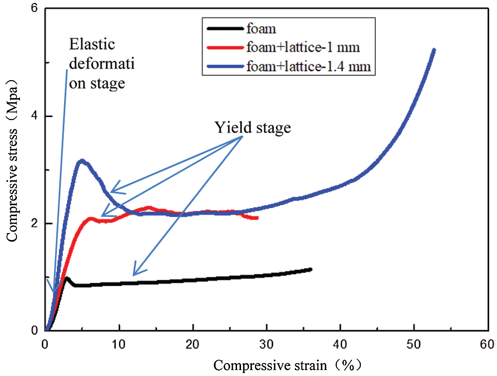
Figure 5: Compressive stress–strain curves about the three kinds of specimens
Table 4: The results of measured values and theoretical predictions
From the energy absorption characteristic curves in Fig. 6, it can be seen that the energy absorption of the foam sandwich structure increases linearly with the increase of the displacement load during the compressive tests, which is the inherent properties of the foam materials. The foam has a long yield distance before it is compacted. The foam is dense when the foam is compressed to 20% of the original volume. In the compressive tests, the load increases linearly with displacement before yielding, so in the energy absorption-compressive strain curves, the curves of the structure before yielding are the quadratic parabola. When the lattice stitched foam sandwich structure with the 1 mm diameter core rods reaches the yield stage, the core rods are incompletely buckled due to their thinness. The carrying capacity of the core rods has been improved because of the support of the foam. The load changes little under the larger displacement load because the reinforcing rods are made by curing the fiber bundles after being infiltrated with epoxy resin, as well as the loss of carrying capacity of the core rods is caused by the crushing of the epoxy resin attached to the carbon fiber bundles. In the lattice foam sandwich structure with the reinforcing rods diameter of 1.4 mm, due to the higher strength and thicker diameter, most of the core rods lose the load-bearing capacity due to the crushing of the epoxy resin after the structure yields; therefore, the load starts to drop from this time. However, the drop is not very large due to the support of the foam. The energy absorption increases with the increase of the displacement. When the structure reaches the yield stage, the slope of the curve decreases. Under the larger displacement load, the space becomes smaller, the core rods start to contact the upper and lower surfaces, which reaches the compact stage and the load increases with the displacement significant. The energy absorption characteristic of the foam sandwich structure reinforced by the fiber is much higher than that of the foam sandwich structure. The reinforced foam sandwich structure has better energy absorption performance.
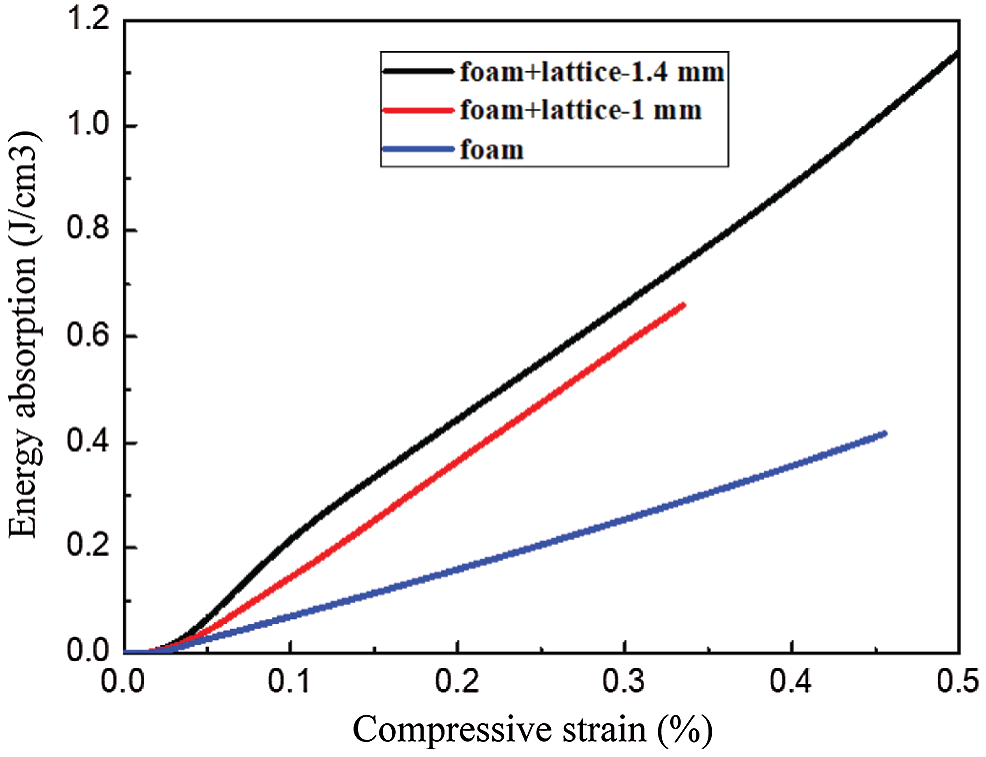
Figure 6: Energy-absorbing characteristics of the sandwich structures under compression
In this part, the homogenization theory is used to predict the shear performance of the lattice stitched foam sandwich structure and the shear test is carried out. The two results are compared and analyzed.
According to the equivalent stiffness tensor,  can be solved.
  is the shear stiffness of the structure. The inverse matrix of the stiffness matrix is the compliance matrix
  , so the shear modulus is
  . The shear modulus of the pyramidal lattice stitched foam is Gs:

Under the shear load, the pyramidal lattice stitched foam sandwich structure is a periodically symmetric structure, so the force analysis of the four core rods in the lattice is shown in Fig. 7. Under the shear load, the fiber rod on one side is pulled and the fiber rod on the other side is compressed. The shear load can be decomposed into axial force named p1 and radial force named p2. When the compression rod has buckling failure, the buckling load [33] is Pbus:

The axial force causes the fiber rod to bend and the radial force causes slight rotation. The tension rod can also be decomposed into axial force and radial force under shear load but the radial force does not cause bending deformation of the core rod. Since the angle between the tension rod and the bottom panel is 60 degrees and the angle between the compression rod and the bottom panel is also 60 degrees. The shear load on the tension rod is the same as on the compression rod. Because the compression rod fails earlier during loading, only the force analysis is performed on the compression rod, which is shown in Fig. 7. Structure begins to break when a buckling failure occurs in the compression rods; at this time, the strength of the structure is formula (13); the structure can still withstand the load due to the tension rod. When the tension rod breaks, the bearing capacity reaches the maximum and the calculation is formula (14). The strength formula of the overall structure can be obtained from a unit cell [32].


p0 is the action of the tension rod in the shear direction;
 is the tensile strength of the core rod.
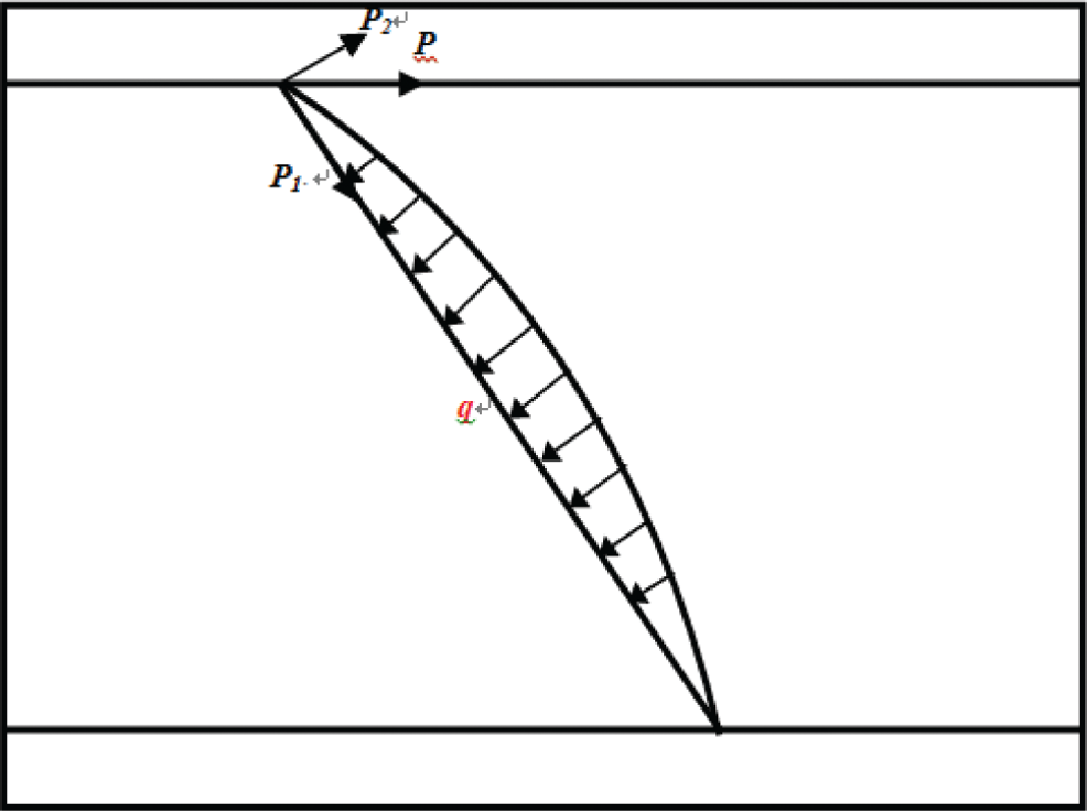
Figure 7: The load state of the fiber core rod under the shear load
In this part, the shear performance of the lattice stitched foam sandwich structure is tested. According to the ASTM C-273 test method, a comparison of shear experiment between the foam sandwich structure and the lattice stitched foam sandwich structure is performed. The size of the specimen is  and the lattice stitched foam core contains
  cells; the specimen and fixture are glued together with epoxy resin. The fixture and the testing machine are hinged at both ends in order to make the direction of the load coincide with the diagonal of the sandwich structure. Load the test specimen with Instron 3382, the rate is 0.5 mm/min. Each group of the test uses three samples for testing to ensure the reliability of the data. The experimental equipment is shown in Fig. 8.

Figure 8: The experimental equipment of the shear tests
The force-displacement curves of the pyramidal lattice stitched foam sandwich structure and the foam sandwich structure under shear load are shown in Fig. 9. Shear elastic modulus can be calculated from the slope of the curves. The shear modulus and shear strength are as follows:


Gc is the shear modulus of the pyramid lattice foam sandwich structure, the unit is MPa;
hc is the height of the core of the pyramid lattice foam sandwich structure, the unit is mm;
l is the length of the pyramid lattice foam sandwich structure, the unit is mm;
b is the width of the pyramid lattice foam sandwich structure, the unit is mm;
 is the load increment of the linear elastic part on the load-displacement curve, the unit is N;
 is the incremental displacement value corresponding to
  on the load-displacement curve, the unit is mm;
 is the shear stress of the pyramid lattice foam sandwich structure, the unit is MPa.
As can be seen from Fig. 9, the foam sandwich structure failure under the shear load is simple. The shear load increases linearly with the increase of displacement and the structure breaks under a shear load of about 9000 N. The carrying capacity of the lattice stitched foam sandwich structure is up to 17000 N, which is increased by nearly 2 times at the small deformation stage. Since the direction of the shear load is along the diagonal in Fig. 8, the specimens are deformed greatly when the displacement load is increased to 3 mm in Fig. 9. At this time, the compression rod in the lattice begins buckling and the load increases more slowly than before with the increase of displacement; at this stage, the compression rod and the foam have failed. Then, as the deformation continues to increase, the tension rod plays the main bearing role. When the tension rod breaks, the overall structure reaches the maximum load-bearing capacity which is significantly higher than that of the foam sandwich structure.
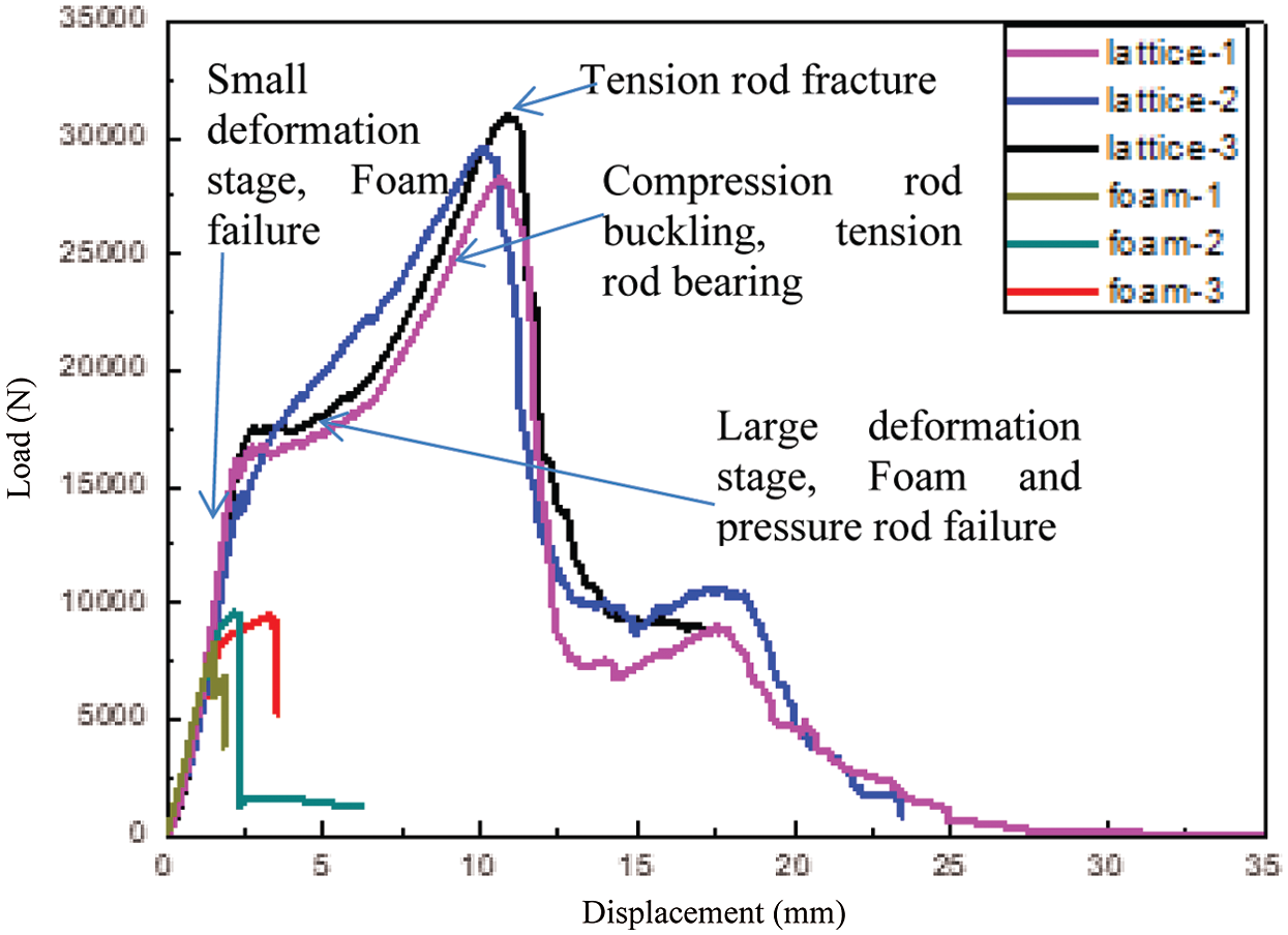
Figure 9: Shear load-displacement curves of the pyramid lattice stitched foam sandwich structure
In the experiment, the failure processes of the two structures are shown in Fig. 10. In the initial stage, the structure is linear elastic which is shown in Fig. 9. As the load increases, the structure is slightly deformed and the compression rod in the unit cell begins buckling. As the load continues to increase, the foam shear fails and separates from the face sheet. The foam is yielding at this stage, but the structure can still bear the load because of the tension rod. When the tension rod breaks, the carrying capacity of the structure reaches the maximum.
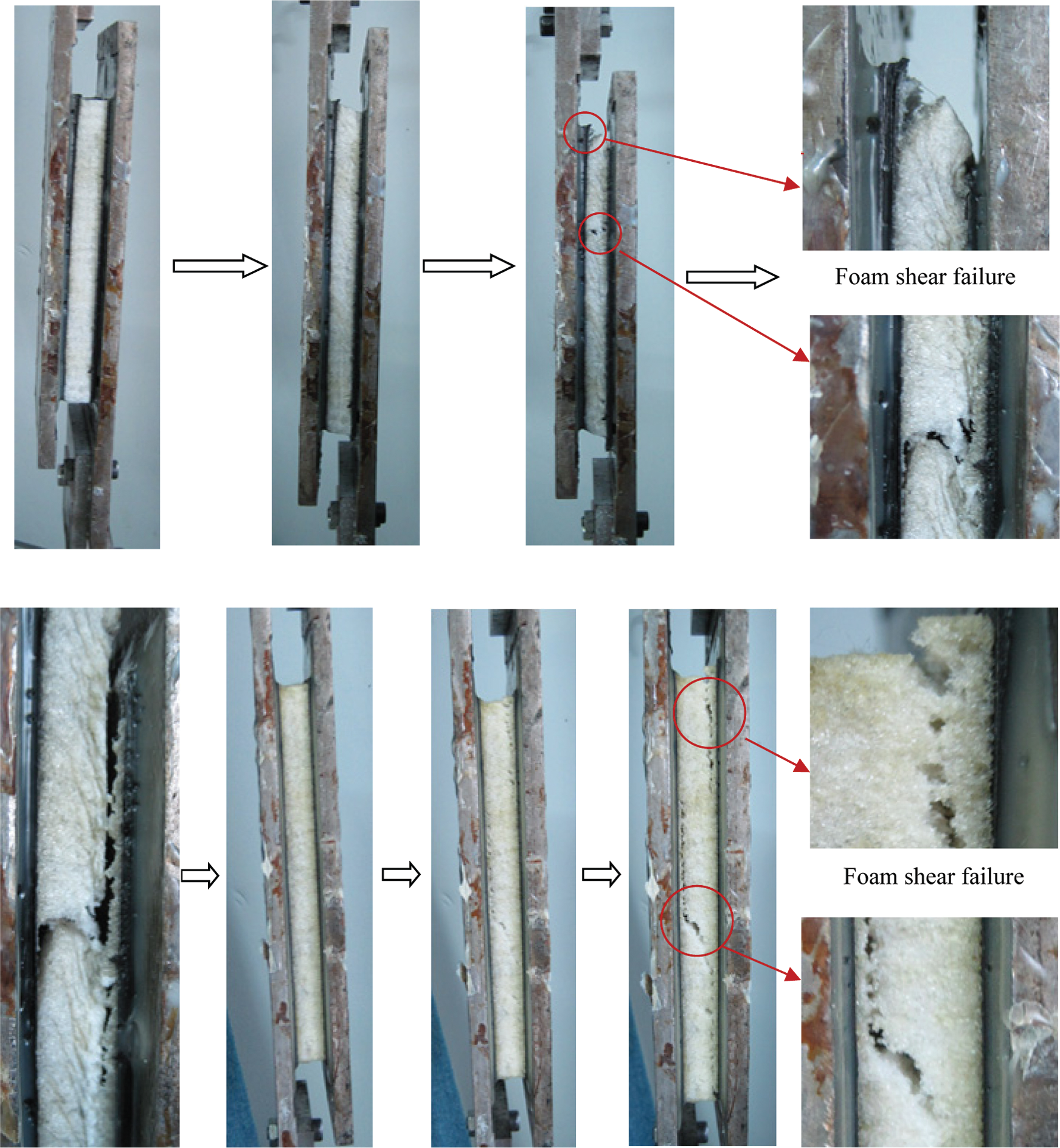
Figure 10: The experimental photos of the failure process of the specimen with the increase of the load
Comparing the failure processes of the two structures, it can be known that the failure forms of the foam sandwich structure are relatively simple, but that of the pyramidal lattice stitched foam sandwich structure are much more complicated. The load-bearing capacity of the foam sandwich structure without the lattice core is greatly reduced. When it fails, the foam is separated from the face sheet and breaks in the direction of 45 degrees which is shown in Fig. 10.
The core rods that are broken during the test are shown in Fig. 11. The failure mode of the core rods is tensile fracture. Because the specimens are prepared by sewing, the core rods are the continuous carbon fiber, so the core rods cannot be pulled out. The shear resistance of the lattice stitched foam sandwich structure is superior to the X-cor foam sandwich structure.
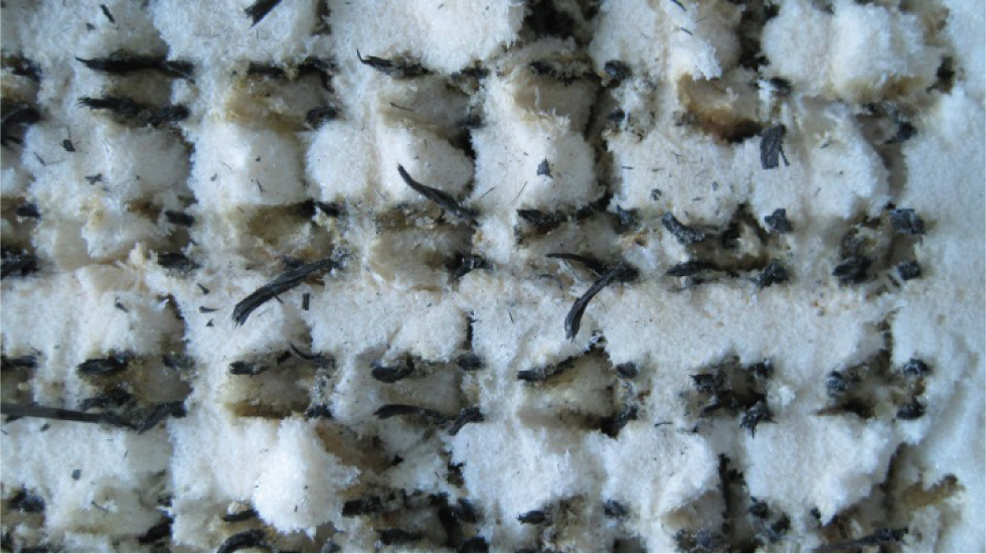
Figure 11: The experimental photo of the core rods broken
The theoretical analysis and experimental results of the pyramidal lattice stitched foam sandwich structure are shown in Tab. 5. From the table, the maximum difference between the theoretical value and the experimental value about shear modulus is 3.501, and the minimum difference is 2.737; the maximum difference between the theoretical value and the experimental value about Euler buckling failure is 0.23, and the minimum difference is 0.02; the maximum difference between the theoretical value and the experimental value about pull-off failure is −0.02, and the minimum difference is −0.17; it can be seen that the experimental results are in good agreement with the theoretical analysis results. Judging from the comparison of the stiffness of the structures, the theoretically calculated value is higher than the experimental value. The results show that in the process of artificial preparation, the specimen inevitably has defects, so the strength and stiffness of the mandrel can not reach the theoretical value. The experimental results of shear strength are the same as the theoretical results basically, which is due to the defects produced in the manufacturing process and the comprehensive effect of epoxy resin on foam strengthening. In the analysis of breakage failure of the core rods, the experimental value is significantly higher than the theoretical value. The reason is as follows: under the shear load, when the core rods are broken, the structure will deform greatly and the angle between the core rod and the face sheet is smaller than the initial angle, so the load of the tension rod in the direction of the shear becomes larger.
Table 5: The results of measured values and theoretical predictions

This part uses the homogenization theory to give the equivalent bending stiffness of the lattice stitched foam sandwich structure and puts forward the corresponding failure mechanism in the analysis process, which is verified by the test results.
In this part, it gives the rigidity of the pyramidal lattice stitched foam sandwich beam under bending load. Based on the reinforced foam sandwich structure prepared by the sewing process. This part has derived several failure modes and the critical loads in every failure mode. In Fig. 12, L is the span of the specimen under bending load. h is the height of the core. t is the thickness of the panel. w is the width of the specimen. d is the distance between the neutral layer of the upper and lower face sheets.  is the acute angle between the core rod and the panel. The specimen is subjected to the load F at the center. In this coordinate system, the stiffness and strength are analyzed along the 3 direction.
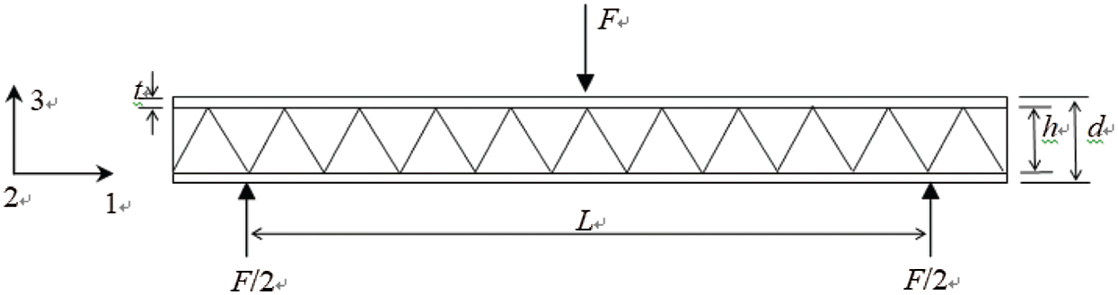
Figure 12: Schematic illustrations of the lattice stitched foam sandwich beam under 3-point bending load
The size of the pyramidal lattice stitched foam sandwich beam is  . The thickness of the core is 15 mm. The span is 122 mm. Since the thickness of the overall structure is not negligible compared with the length and width, the bending deformation and transverse shear deformation of the structure are considered when the sandwich beam is deformed under the bending load. It is similar to the study of deep beam theory while analyzing the deformation of sandwich beam under the bending load. The bending deflection includes two parts, one part is the deflection caused by the bending of the panel and the core, the other part is the deflection caused by the lateral shear of the core. Allen [34] proposed in 1696 that under the three-point bending load, the calculation formula of the deflection at the centre of the sandwich beam is:

 is the deflection of the whole sandwich beam caused by bending;
  is the deflection caused by the shear of the core in 3-direction;
  is the equivalent bending stiffness of the sandwich beam;
  is the equivalent shear stiffness of the sandwich beam.


 can be deduced from the parallel axis theorem. The first term is the bending stiffness of the panel to itself; the second term represents the bending stiffness of the panel to the centered of the core of the sandwich beam; the third term is the bending stiffness of the equivalent core.
  is the equivalent stiffness tensor of the equivalent core in the homogenization theory;
  represents the effective cross-sectional area of the sandwich core;
  is the shear stiffness tensor of the equivalent core of the homogenization theory; Vp is the volume content of fiber rods in a unit cell, which means the relative density
  in the lattice, both
  and
and  can be derived from the equivalent stiffness tensor of the sandwich structure of the homogenization theory.
When the pyramidal lattice stitched foam sandwich structure is under the three-point bending load, the main bearers of the bending load are the upper and lower face sheets which are high modulus materials; the shear force is mainly borne by the core. Due to the different types of load carried by each part of the structure, the failure modes of the structure are also diverse. In this paper, four failure modes are proposed based on the pyramidal lattice stitched foam sandwich beams under three-point bending load, as well as the analytical formulas for critical loads in each failure mode are given:
1) Panel yield is a failure mode resulting from the compressive stress of the top and bottom face sheets of the pyramidal lattice stitched foam sandwich beam reaching the strength limit under the three-point bending load. Critical load:

 is the yield strength that causes the panel to collapse.
2) Foam core yield is a failure mode. It occurs when the foam deforms significantly during loading. Because the foam is a kind of porous low modulus material with a large plastic yielding area. Critical load:

 is the yield strength of the foam.
3) The core shear yield refers to a failure mode caused by the shear stress on the equivalent unit cell of the pyramidal lattice stitched foam structure reaching the shear strength limit. Critical load:

The content in brackets is the shear yield strength of the equivalent core. The first part is the shear yield strength of the core rod; the second part is the shear strength of the foam. The foam is a kind of porous and compressive material. Its elastic range is small and it can last a long time in the plastic yield stage after the deformation, so it assumes that the foam has reached the shear yield stage when the core rod reaches the shear yield stage.  is the yield strength of the core rod and
  is the shear yield strength of the foam.
4) The core shear buckling refers to the failure mode of the equivalent element of the pyramidal lattice stitched foam structure. It occurs when the shear stress reaches the limit of shear buckling strength. Critical load:

The content in brackets is the shear buckling strength of the equivalent core. The first part is the shear buckling strength of the core rod; the second part is the shear strength of the form; Es is the elastic modulus of the core rod.
This part tests and compares the pyramidal lattice stitched foam sandwich structure and the foam sandwich structure. According to the test standard for three-point bending, the size of the specimens is  ; the thickness of the sandwich core is 15 mm; the inclination angle of the core rod is 60
 ; the number of unit cells is
  and the span is 122 mm. Instron 3382 universal testing machine is used to apply displacement load on the specimens and the loading rate is 1 mm/min.
The pyramidal lattice stitched foam sandwich structure has multiple failure modes under three-point bending load. However in fact, only one or two failure modes occur when the structure loses its carrying capacity. The destruction process of the lattice stitched foam sandwich panels is shown in Fig. 13. Because the core rods are embedded in the foam, foam shear and panel damage can be observed only. The failure process of the fiber core rods cannot be observed, but the crisp destruction of the core rods during the loading can be heard. The failure process of the foam sandwich structure under three-point bending load is shown in Fig. 14. Since there is no fiber core rod in the form sandwich structure its structural rigidity is far less than that of the pyramidal lattice stitched foam sandwich structure. The deformation of the structure is large and the failure mode is single because the strength and rigidity of the foam is much smaller than that of the panel. And its bending failure is caused by the breakage of the foam.

Figure 13: Image of the lattice stitched foam sandwich panels during the three-point bending tests
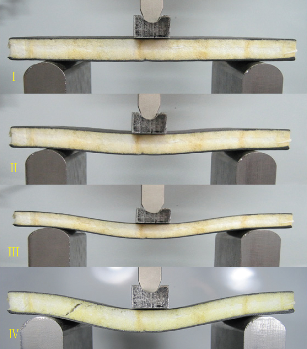
Figure 14: Image of the foam sandwich panels during the three-point bending tests
Load-displacement curves of pyramidal lattice stitched foam sandwich structure and foam sandwich structure under three-point bending load are shown in Fig. 15. The fiber core rods have a significant toughening effect and the stiffness is significantly improved under the three-point bending load. The slope of the linear part of the curve of the pyramidal lattice stitched foam sandwich structure is 3.19 times that of the linear part of the foam sandwich structure. Due to the increased rigidity of the pyramidal lattice stitched foam sandwich structure, the deformation under the three-point bending load is significantly reduced. Its failure displacement is reduced to 1/7 of that of the foam sandwich structure. The maximum load is increased by more than 2000 N. The contribution of the fiber core rods in the three-point bending resistance cannot be underestimated.
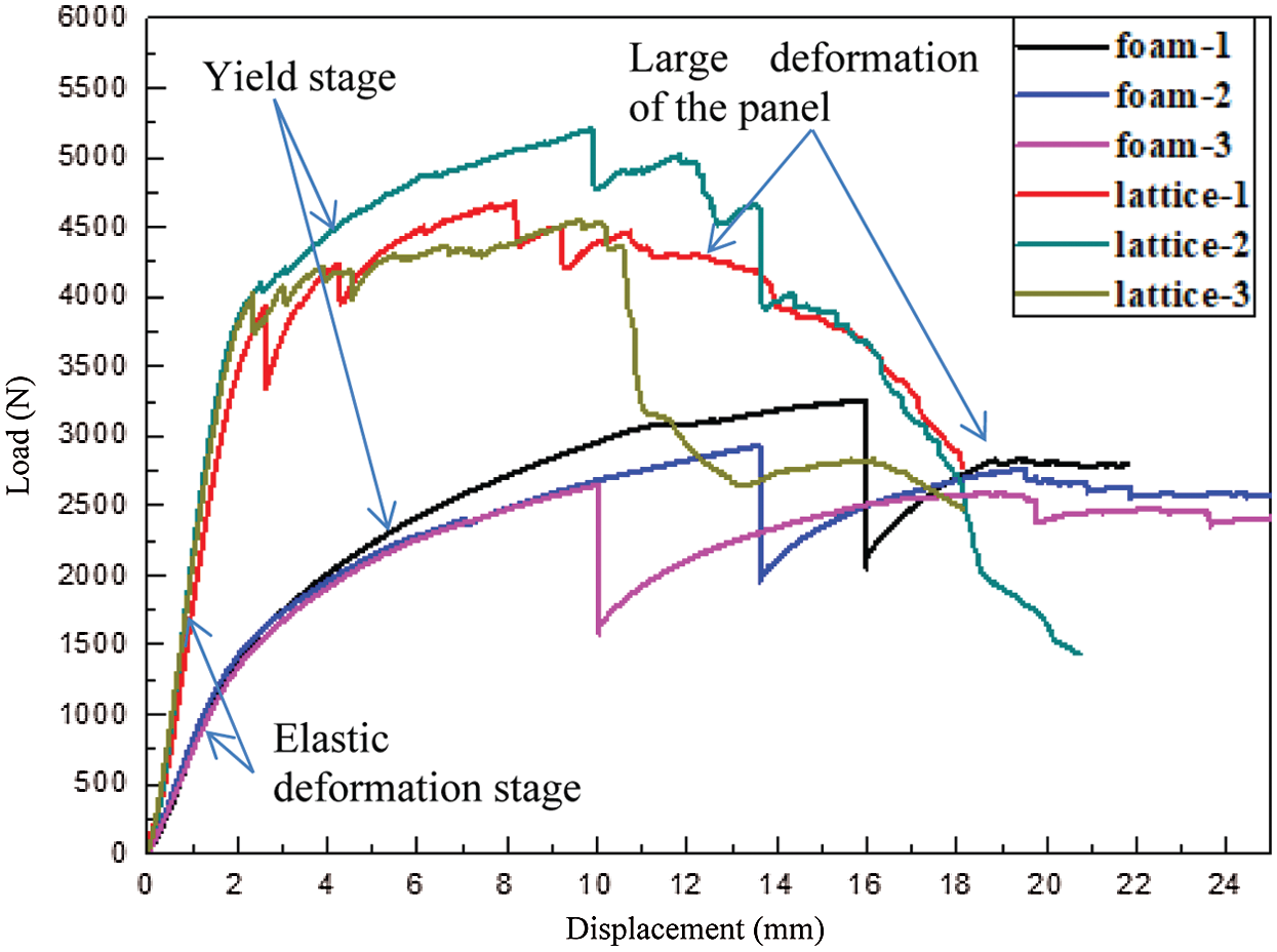
Figure 15: Load-displacement curves of the foam sandwich structures under the three-point bending tests
The theoretical analysis results and experimental results of the pyramidal lattice stitched foam sandwich structure and foam sandwich structure are shown in Tab. 6. From Fig. 15 and Tab. 6, when the pyramidal lattice stitched foam sandwich structure begins to fail both the theoretical analysis results and experimental results indicate that the foam yields first. Although the foam is yielding, the structure still has the ability to withstand the load. Since the structure has already suffered some damage, the load-displacement curve becomes non-linear after the foam yielding. During this stage, the fiber core rods gradually occur shear buckling failure. As the deformation of the structure increases gradually, the damage of the structure also expands, which is resulting in a sharp decrease in the stiffness of the structure and the loss of its carrying capacity. The load when the core rods break is the maximum bearing capacity of the structure, which is shown in Fig. 15. In the tests, the failure mode of the foam sandwich structure is relatively simple, but the experimental value is higher than the theoretical analysis value. The reason is as follows: When the foam sandwich structure fails, the displacement is much higher than that of the lattice stitched foam sandwich structure. Because of the low rigidity of the foam sandwich structure, its failure deformation is very large. The high-strength and high-modulus face sheets also deform greatly but not destroy. Therefore, there is an elastic reaction force which leads to this result.
Table 6: The results of measured values and theoretical predictions

In this paper, the pyramidal lattice stitched foam sandwich structure was fabricated by weaving and interleaving. The study has conducted theoretical analysis and experimental tests on compressive, shear and three-point bending performances of two structures including the lattice stitched foam sandwich structure and the foam sandwich structure. Some conclusions are drawn.
First, the lattice core has a significantly toughening effect on the structure. The compressive stiffness and shear stiffness of the lattice stitched foam sandwich structure are nearly twice that of the foam sandwich structure, even the bending stiffness increased by nearly 3 times. The shear strength and the bending strength are increased by more than two times and the shear strength limit is increased by nearly 3.5 times even.
Second, based on the homogenization theory, the equivalent stiffness matrix of the pyramidal lattice stitched foam sandwich structure is derived and analytical formulas for the equivalent stiffness of the structure under plane compression and shear are derived. The article analyzes the mechanical model of the unit cell of the pyramidal lattice stitched foam sandwich structure and deduces the different strength under three kinds of loads respectively. And the models are revised according to the constraint conditions at the ends of the core rods. It compares the theoretical prediction and experimental data to give a reasonable explanation of failure modes during the experiment. It can be inferred that the experimental value and the theoretical value are the same roughly.
Third, numerical calculation methods are used to study the plane compression and shear response of the pyramidal lattice stitched foam sandwich structure. By analyzing the unit cell model, the stress field distributions of the two structures under plane compressive load and shear load are analyzed. The internal deformation state of the core that cannot be observed in the experiment is observed and the failure mode is analyzed. The comparison results show that the theoretical value is compatible with the experimental value.
Based on the research, the author believes that further research needs to be carried out. The preparation of lattice sandwich structure needs further improvement and development to overcome the problems of high cost, low efficiency and limited size. The enhancement effect of different cores should be paid more attention to.
Funding Statement: This research is supported by “National Natural Science Foundation of China” (No. 11972140).
Conflicts of Interest: The authors declare that they have no conflicts of interest to report regarding the present study.
1. Zhang, Y. W., Chen, L. Q., Su, C., Ni, Y., Zhang, J. et al. (2019). A multifunctional lattice sandwich structure with energy harvesting and nonlinear vibration control. Composite Structures, 221, 110875. DOI 10.1016/j.compstruct.2019.04.047. [Google Scholar] [CrossRef]
2. Harte, A. M., Fleck, N. A., Ashby, M. F. (2000). Sandwich panel design using aluminum alloy foam. Advanced Engineering Materials, 2(4), 219–222. [Google Scholar]
3. Kiratisaevee, H., Cantwell, W. J. (2004). The impact response of aluminum foam sandwich structures based on a glass fiber-reinforced polypropylene fiber-metal laminate. Polymer Composites, 25(5), 499–509. DOI 10.1002/pc.20043. [Google Scholar] [CrossRef]
4. Manalo, A. C., Aravinthan, T., Karunasena, W., Islam, M. M. (2010). Flexural behaviour of structural fibre composite sandwich beams in flatwise and edgewise positions. Composite Structures, 92(4), 984–995. DOI 10.1016/j.compstruct.2009.09.046. [Google Scholar] [CrossRef]
5. Hu, B., Wu, L. Z., Xiong, J., Ma, L., Yang, W. et al. (2019). Mechanical properties of a node-interlocking pyramidal welded tube lattice sandwich structure. Mechanics of Materials, 29, 290–305. DOI 10.1016/j.mechmat.2018.12.006. [Google Scholar] [CrossRef]
6. Wu, Z., Liu, W., Wang, L., Fang, H., Hui, D. (2014). Theoretical and experimental study of foam-filled lattice composite panels under quasi-static compression loading. Composites Part B: Engineering, 60, 329–340. DOI 10.1016/j.compositesb.2013.12.078. [Google Scholar] [CrossRef]
7. Wang, L., Liu, W., Wan, L., Fang, H., Hui, D. (2014). Mechanical performance of foam-filled lattice composite panels in four-point bending: Experimental investigation and analytical modeling. Composites Part B: Engineering, 67, 270–279. DOI 10.1016/j.compositesb.2014.07.003. [Google Scholar] [CrossRef]
8. Yan, L. L., Han, B., Yu, B., Chen, C. Q., Zhang, Q. C. et al. (2014). Three-point bending of sandwich beams with aluminum foam-filled corrugated cores. Materials and Design, 60, 510–519. DOI 10.1016/j.matdes.2014.04.014. [Google Scholar] [CrossRef]
9. Lascoup, B., Aboura, Z., Khellil, K., Benzeggagh, M. (2006). On the mechanical effect of stitch addition in sandwich panel. Composites Science and Technology, 66(10), 1385–1398. DOI 10.1016/j.compscitech.2005.09.005. [Google Scholar] [CrossRef]
10. Koissin, V., Shipsha, A., Skvortsov, V. (2009). Compression strength of sandwich panels with sub-interface damage in the foam core. Composites Science and Technology, 69(13), 2231–2240. DOI 10.1016/j.compscitech.2009.06.014. [Google Scholar] [CrossRef]
11. Nanayakkara, A., Feih, S., Mouritz, A. P. (2011). Experimental analysis of the through-thickness compression properties of z-pinned sandwich composites. Composites Part A: Applied Science and Manufacturing, 42(11), 1673–1680. DOI 10.1016/j.compositesa.2011.07.020. [Google Scholar] [CrossRef]
12. Lascoup, B., Aboura, Z., Khellil, K., Benzeggagh, M. (2010). Homogenization of the core layer in stitched sandwich structures. Composites Science and Technology, 70(2), 350–355. DOI 10.1016/j.compscitech.2009.11.006. [Google Scholar] [CrossRef]
13. Che, L., Xu, G. D., Zeng, T., Cheng, S., Zhou, X. W. et al. (2014). Compressive and shear characteristics of an octahedral stitched sandwich composite. Structures, 112, 179–187. DOI 10.1016/j.compstruct.2014.02.012. [Google Scholar] [CrossRef]
14. Kazemahvazi, S., Khokar, N., Hallstrom, S., Wadley, H. N., Deshpande, V. S. (2016). Confluent 3D-assembly of fibrous structures. Composites Science and Technology, 127, 95–105. DOI 10.1016/j.compscitech.2016.02.034. [Google Scholar] [CrossRef]
15. Song, Z. Z., Cheng, S., Zeng, T., Yang, F., Jing, S. D. et al. (2015). Compressive behavior of C/SiC composite sandwich structure with stitched lattice core. Composites Part B: Engineering, 69, 243–248. DOI 10.1016/j.compositesb.2014.10.012. [Google Scholar] [CrossRef]
16. Kooistra, G. W., Deshpande, V. S., Wadley, H. N. G. (2004). Compressive behavior of age hardenable tetrahedral lattice truss structures made from aluminium. Acta Materialia, 52(14), 4229–4237. DOI 10.1016/j.actamat.2004.05.039. [Google Scholar] [CrossRef]
17. Queheillalt, D. T., Wadley, H. N. G. (2009). Titanium alloy lattice truss structures. Materials & Design, 30(6), 1966–1975. DOI 10.1016/j.matdes.2008.09.015. [Google Scholar] [CrossRef]
18. Kooistra, G. W., Wadley, H. N. G. (2007). Lattice truss structures from expanded metal sheet. Materials & Design, 28(2), 507–514. DOI 10.1016/j.matdes.2005.08.013. [Google Scholar] [CrossRef]
19. Queheillalt, D. T., Murty, Y., Wadley, H. N. G. (2008). Mechanical properties of an extruded pyramidal lattice truss sandwich structure. Scripta Materialia, 58(1), 76–79. DOI 10.1016/j.scriptamat.2007.08.041. [Google Scholar] [CrossRef]
20. Queheillalt, D. T., Wadley, H. N. G. (2005). Pyramidal lattice truss structures with hollow trusses. Materials Science and Engineering: A, 397(1), 132–137. DOI 10.1016/j.msea.2005.02.048. [Google Scholar] [CrossRef]
21. Kevin A.F. (2007). Carbon fiber composite pyramidal lattice structures. USA: University of Virginia. [Google Scholar]
22. Xu, G. D., Zhai, J. J., Zeng, T., Wang, Z. H., Cheng, S. et al. (2015). Response of composite sandwich beams with graded lattice core. Composite Structtures, 119, 666–676. DOI 10.1016/j.compstruct.2014.09.042. [Google Scholar] [CrossRef]
23. Wang, B., Wu, L., Ma, L., Wang, Q., Du, S. (2009). Fabrication and testing of carbon fiber reinforced truss core sandwich panels. Journal of Materials Science & Technology, 25(4), 547–550. [Google Scholar]
24. Wang, B., Wu, L., Ma, L., Sun, Y., Du, S. (2010). Mechanical behavior of the sandwich structures with carbon fiber-reinforced pyramidal lattice truss core. Materials and Design, 31(5), 2659–2663. DOI 10.1016/j.matdes.2009.11.061. [Google Scholar] [CrossRef]
25. Rajkumar, S. (2020). Strength and stiffness characteristics of A3003 aluminum honeycomb core sandwich panels. Materials Today: Proceedings. DOI 10.1016/j.matpr.06.348. [Google Scholar] [CrossRef]
26. Chen, Q., Du, S. R., Jiang, Z. Y., Liu, Y. Q., Du, R. K. (2020). Mechanical properties of foam sandwich with chopped-glass-fiber/carbon nanotube reinforced hierarchical structure interlayer. Polymer Composite, 41(8), 3411–3420. DOI 10.1002/pc.25630. [Google Scholar] [CrossRef]
27. Wang, Y., Zhang, Z., Xue, X., Zhang, L. (2020). Experimental investigation on enhanced mechanical and damping performance of corrugated structure with metal rubber. Thin-Walled Structures, 154, 106816. DOI 10.1016/j.tws.2020.106816. [Google Scholar] [CrossRef]
28. Lee, M. G., Yoon, J. W., Han, S. M., Suh, S. M., Kang, K. J. (2013). (Bending response of sandwich panels with discontinuous wire-woven metal cores. Materials and Design, 10, 5493–5517. DOI 10.1016/j.matdes.2013.10.035. [Google Scholar] [CrossRef]
29. Rejab, M. R. M., Cantwell, W. J. (2013). The mechanical behaviour of corrugated-core sandwich panels. Composites: Part B, 47, 267–277. DOI 10.1016/j.compositesb.2012.10.031. [Google Scholar] [CrossRef]
30. Tmoshenko, S. P., Gere, J. M. (1961). Theory of elastic stability. Mc Graw-Hill, New York. [Google Scholar]
31. Zheng, T. T., Yan, H. Z., Li, S., Cheng, Y. P., Zou, L. X. (2020). Compressive behavior and failure modes of the wood-based double X-type lattice sandwich structure. Journal of Building Engineering, 30, 101176. DOI 10.1016/j.jobe.2020.101176. [Google Scholar] [CrossRef]
32. Wang, B., Hu, J. Q., Li, Y. Q., Yao, Y. T., Wang, S. X., et al. (2018). Mechanical properties and failure behavior of the sandwich structures with carbon fiber-reinforced X-type lattice truss core. Composite Structures, 185, 619–633. DOI 10.1016/j.compstruct.2017.11.066. [Google Scholar] [CrossRef]
33. Li, S. G., Hu, R. S., Cheng, J., Hu, Y. C. (2019). Compressive effect of jute fiber corrugated lattice sandwich structure. Journal of Reinforced Plastics and Composites, 39(5–6), 209–218. DOI 10.1177/0731684419881785. [Google Scholar] [CrossRef]
34. Allen, H. G. (1969). Analysis and design of structural sandwich panels. Pergamon Press: Oxford. [Google Scholar]
 | This work is licensed under a Creative Commons Attribution 4.0 International License, which permits unrestricted use, distribution, and reproduction in any medium, provided the original work is properly cited. |