| Computer Modeling in Engineering & Sciences |
DOI: 10.32604/cmes.2021.012839
ARTICLE
CFD-Based Simulation and Analysis of Hydrothermal Aspects in Solar Channel Heat Exchangers with Various Designed Vortex Generators
1Department of Physics, University of M’sila, M’sila, 28000, Algeria
2Laboratory of Physics and Chemistry of Materials, University of M’sila, M’sila, 28000, Algeria
3Unit of Research on Materials and Renewable Energies, Department of Physics, Abou Bekr Belkaid University, Tlemcen, 13000, Algeria
4Faculty of Engineering, Kuwait College of Science and Technology, Doha District, Kuwait
5Center of Excellence in Desalination Technology, King Abdulaziz University, Jeddah, 21589, Saudi Arabia
6Department of Technology, University Center of Naama, Naama, 45000, Algeria
7Unité de Recherche en Energies Renouvelables en Milieu Saharien, URERMS, Centre de Développement des Energies Renouvelables, CDER, Adrar, 01000, Algeria
*Corresponding Author: Ali J. Chamkha. Email: a.chamkha@kcst.edu.kw
Received: 14 July 2020; Accepted: 09 September 2020
Abstract: The hydrothermal behavior of air inside a solar channel heat exchanger equipped with various shaped ribs is analyzed numerically. The bottom wall of the exchanger is kept adiabatic, while a constant value of the temperature is set at the upper wall. The duct is equipped with a flat rectangular fin on the upper wall and an upstream V-shaped baffle on the lower wall. Furthermore, five hot wall-attached rib shapes are considered: trapezoidal, square, triangular pointing upstream (type I), triangular pointing downstream (type II), and equilateral-triangular (type III) cross sections. Effects of the flow rates are also inspected for various Reynolds numbers in the turbulent regime (1.2×1043.2×104)–η). The highest performance (η) value is given for the II-triangular rib case in all Re values, while the square-shaped ribs show a significant decrease in the η along the achieved Re range. The η value at Remax is 2.567 for the II-triangular roughness case. Compared with the other simulated cases, this performance is decreased by about 3.768% in the case of I-triangular ribs, 15.249% in the case of III-triangular ribs, 20.802% in the case of trapezoidal ribs, while 27.541% in the case of square ribs, at the same Remax. Also, a comparison is made with air-heat exchangers that have non-rough walls and contain cross-shaped VGs presented previously, in order to highlight the effectiveness of the rough surface presence in the baffled and finned channels. The obtained results indicated that the triangular-shaped rib (type II) has the most significant hydrothermal behavior than the other cases. This indicates the necessity of roughness heat transfer surfaces for finned and baffled channels to improve significantly the performance of the air-heat exchangers they contain.
Keywords: CFD; heat exchanger; vortex generators; ribs; hydrothermal aspects
Nomenclature
 | Constant in k- model model |
 | Constant in k- model model |
| Cp | Specific heat, J kg−1 K−1 |
 | Hydraulic diameter of the exchanger, m |
| f | Average coefficient of friction |
 | Factor of friction for smooth exchanger |
| H | Height of exchanger, m |
| h | Height of attached VG, m |
 | Height of attached rib, m |
| k | Kinetic energy of turbulence, m2 s−2 |
| L | Length of exchanger, m |
 | Inlet–-1st VG space, m |
 | 2nd VG–-exit space, m |
| Nu | Average Nusselt number of the ribbed and baffled exchanger |
 | Average Nusselt number for the smooth exchanger |
| P | Pressure, Pa |
 | Dynamic pressure, Pa |
| Pr | Number of Prandtl |
| Re | Number of Reynolds |
| S | Space between VGs, m |
| T | Temperature, K |
 | Inlet fluid temperature, K |
 | Wall temperature, K |
| u | X-velocity, m s−1 |
 | Intake velocity, m s−1 |
 | Average velocity, m s−1 |
| v | Y-velocity, m s−1 |
| W | Width of exchanger, m |
| w | Thickness of the fixation base of the rib, m |
 | Thickness of the upper face of the rib, m |
Greeks Symbols
 | Attack angle, degree |
 | Thermal enhancement factor |
 | Thermal-conductivity, W m−1 K−1 |
 | Dynamic viscosity, kg m−1 s−1 |
 | Turbulent viscosity, kg m−1 s−1 |
 | Density, kg m−3 |
 | Constant in k-equation |
 | Constant in  -equation -equation |
 | Wall-shear-stress, Pa |
Subscript
| atm | Atmosphere |
| f | Fluid |
| in | Intake |
| out | Outlet |
| t | Turbulent |
| w | Wall |
| x | Local |
The insertion of roughness elements in channel heat exchangers is well-known as an excellent technique to enhance the overall performances (Chen et al. [1], Tien et al. [2], El-Askary et al. [3], Sharma et al. [4] and Guan et al. [5]). This technique is largely applied in the design of solar heat exchangers (Menasria et al. [6], Tan et al. [7], Ghritlahre et al. [8], Shirvan et al. [9] and Baissi et al. [10]). The insertion of ribs yields variations in the flow streamlines, modification in the thermal transfer rates, and an augmentation in the turbulence levels, which generates in enhanced thermal exchange (Tarasevich et al. [11], Omari et al. [12], Gorelov [13], Joseph et al. [14] and Kumar et al. [15]).
Various research studies have been achieved on this subject, among other works, Patankar et al. [16] conducted the first numerical investigation on the fully developed hydrothermal behavior of laminar-type flows through a duct. The simulated fluid field was characterized by large vortex areas, with a strong blockage effect within the conduit, resulting in improved Nusselt number values compared to those in conventional-type laminar flows. Kelkar et al. [17] characterized numerically the laminar flow details inside a channel having staggered baffles. They observed an increase in the thermal performance with increased baffle height and reduced baffle spacing. By using numerical simulations, Webb et al. [18] determined the hydrothermal details in a smooth duct with staggered vortex generators. Their study indicated that the case of high numbers of Prandtl, such as those contained in fluorocarbons or water, can enhance heat transfer and better in the presence of heat transfer by conduction. Under a laminar flow regime and for a channel with a blockage ratio of 0.5, Lopez et al. [19] reported that the 3D impact on the friction increases with the rise of Reynolds number. Cheng et al. [20] inspected numerically the laminar forced-convection within channels equipped with two series of vortex generators. The results demonstrated that the flow field was affected by the relative station given by the fin arrays. While, the in-line type arrangement of considered fins proved ineffective, due to the presence of recirculation cells distributed along the channel surfaces. Guo et al. [21] inserted a single vortex generator (VG) at the entrance of a duct to enhance the laminar forced-convection behavior, with a special attention to the influence of the VG height. According to the analysis of their study, there is a three-dimensional effect on both the fields of flow and temperature. In the content of the fin dynamically, while on the entire course of the channel thermally, as the separation and recirculation lengths improve with the improvement of the flow and blockage rates, before and after the VG, respectively. The numerical study achieved by Bazdidi-Tehrani et al. [22] on the laminar hydrothermal behavior in a horizontal channel with in-lined VGs revealed that that the baffle-type obstacles are inefficient for large blockage ratio values. Hwang et al. [23] reported in their numerical paper on the turbulent flow around baffles that the zone of recycling flow decreases with the rise of the baffle length. Yuan et al. [24] inspected numerically the laminar hydrothermal characteristics inside a baffled channel. Compared with the unbaffled duct, the Nusselt number has been increased up to four times, but with much greater pressure losses. Tsay et al. [25] obtained an improvement in the Nusselt number by 190% through the installation of a VG in a backward-facing step. On the other hand, by just a slight change in the VG positioning, the characteristics of heat transfer change strongly. Also, the average value of Nusselt number increased by about 3% when the VG thickness increased from 0.2 to 0.5. Pirouz et al. [26] used the Lattice–Boltzmann method to examine the hydrothermal details of a baffled channel and they confirmed that this method is suitable for the study of such problems. Chien et al. [27] experimentally conducted a convective boiling test inside micro-channels containing fins with a dielectric working fluid of the FC-72 type. As expected, the fluid passes both the high temperature and boiling phases as the pressure-drop increases across the channel, while its surface temperature-difference decreases significantly. In another study, Chien et al. [28] experimentally enhanced heat transfer in the surface of a micro-gap through the use of fins that were finely structured and staggered in alignment. Regardless of the flow type, the convective coefficient of heat transport improves as the mass flux increases. Moreover, the heat flux proved to be ineffective on pressure-drop in the single-phase flow presence, while strongly affecting the same variable in the two-phase flow case, where the pressure-drop increased with the increase in the mass flux. Nasiruddin et al. [29] compared the performance of three different baffle orientations within a channel heat exchanger. The inclination of the baffle towards the downstream side has yielded the highest thermal improvement with the minimum pressure loss. Mousavi et al. [30] used the CFD method to determine the hydrothermal behavior within a duct provided with solid baffles and fins. For Re between  and
and  , Tandiroglu et al. [31] inspected the forced-convection in a baffled circular pipe. Demartini et al. [32] used the hot wire anemometry and the FLUENT software to study the airflow behavior within a baffled duct. Also, Acharya et al. [33] studied numerically and by experiments the turbulent heat transfer past a surfaced-mounted obstacle.
Other similar studies can be found in literature as Ghanbari et al. [34], Karami et al. [35], Wu et al. [36], Chamoli [37], Mana et al. [38], Chang et al. [39], Salem et al. [40], Ghanbari et al. [41], Jeong et al. [42] and Gautam et al. [43] interested in the perforated VG. Dutta et al. [44–46] compared the efficiency of perforated and solid baffles within rectangular channels. More recently, Salhi et al. [47] inspected numerically the three-dimensional effect of the transverse separation length between the deflector perforations on the performance of a rectangular-channel heat-exchanger thermal-device.
Other investigations examined the installation of porous baffles in ducts. Abbasi et al. [48], Tian et al. [49], Mohammadi et al. [50], Li et al. [51], Wang et al. [52], Pourrahmani et al. [53], Kiwan et al. [54], Esfe et al. [55], Gupta et al. [56], Zhao et al. [57], Toghraie et al. [58], Wang et al. [59], Siavashi et al. [60], Shamsabadi et al. [61], Mesgarpour et al. [62], Kiwan [63], Nabati et al. [64], Sowmya et al. [65], Ghalambaz et al. [66] and Ho et al. [67] inspected the influence of several aspect ratio ducts and various configurations of porous VGs. Their results suggested a powerful relationship between of the thermal exchange and the assigned parameters.
Furthermore, many studied have been conducted suggesting various newly designed baffles, such as the Flat and trapezoidal [68], Flat and triangular [68], Flat and arc [69], [70–72], Flat and [68,70,73–75], V-downstream [70], Flat and V-downstream [68,70,76], W [77], Diamond [78], drop [79], delta [80], angled [81], helical [82], continuous [83] and Z-shaped [84].
The engineering analysis of previous studies can classify the heat transfer enhancement methodology into two different techniques. Several studies have used heat exchangers with smooth channels containing transverse/longitudinal VGs (baffles and/or fins) in various shapes. On the other hand, other used rough walls (ribbed surface) rather than extended surfaces (VGs). Both cases demonstrated significant improvement in heat transfer. This study is a combination of these heat transfer reinforcement techniques, in order to achieve a wider hydrothermal performance inside the heat exchanger. This is the motivation of the current work, in which a detailed analysis of the flow structure and its effect on the efficiency of a solar ribbed, finned and baffled channel air-heat exchanger is highlighted. This work aims to enhance the hydrothermal behavior of air within channel heat exchangers. An attempt is made to highlight the influence of flow rates, as well as the design of ribs. Several shapes of ribs are considered, including the trapezoidal, square, triangular pointing upstream (type I), triangular pointing downstream (type II), and the equilateral-triangular (type III) shape. The study is concerned with the following:
• The current filed lines are shown in various models of ribs subject to a turbulent Newtonian flow.
• The effect of duct blockage on the mean velocity and its two components (axial and transverse) is shown at various stations.
• Hydrodynamic analysis of direct and reverse flows and their relationship to dynamic pressure.
• The simultaneous effect of VGs and ribs on the exchanger performance.
• In order to highlight the effectiveness of the proposed model, a comparison with referenced baffled and finned heat exchangers without ribs [68–70] is presented.
The hydrothermal characteristics of air flowing through a solar finned and baffled channel heat exchanger [85] (Fig. 1) are investigated by the CFD method. Its channel is equipped with two VGs (upper fin and lower baffle) in a staggered arrangement. Two shapes of VGs are considered, namely: the straight and  -attack V-upstream VGs inserted on the top and lower exchanger surfaces, respectively. A constant value of the temperature is set at the top wall (Tw = 375 K), while the bottom one was thermally insulated. Furthermore, five shapes of upper wall-attached ribs are considered: square (Fig. 1a), trapezoidal (Fig. 1b), triangular pointing upstream (or triangular type I, Fig. 1c), triangular pointing downstream (or triangular type II, Fig. 1d), and the equilateral-triangular (or triangular type III, Fig. 1e) -shaped ribs. The geometrical dimensions of the computational domain, i.e., length (L), height (H), and hydraulic diameter (Dh) of the channel, height (h), thickness (e), and spacing of the VGs (S), as well as the inlet (Lin) and outlet (Lout) distances, are 0.554, 0.146, and 0.167 m, 0.08 m, 0.01 m, 0.142 m, 0.218 m, and 0.174 m, respectively [32].
Figure 1: Finned and baffled type channel heat exchanger with (a) square, (b) trapezoidal, (c) triangular, (d) II-type triangular, (e) III-type triangular ribs on its hot wall [85]
Our simulation is based on real experimental studies, this is why the physical and geometrical parameters are the same as those of Demartini et al. [32]. Then, and after achieving the verification of our predicted data against the experimental data [32], we tried to contribute with new geometrical suggestions to enhance the overall performances of the exchanger.
For turbulent flow conditions, and the hydrothermal behavior is two-dimensional. The fluid nature is Newtonian as well as incompressible with a constant value of the velocity profile at the inlet [32]. The condition ‘no-slip boundary’ is used for the surfaces of the exchanger [32]. The atmospheric pressure ( ) is presented at the duct exit [32]. The constant values Tin = 300 and Tw = 375 K are set at the inlet and the upper wall of the exchanger, respectively [29]. However, the bottom wall is considered as adiabatic [45].
The governing equations of the problem under investigation are written as [29]:
The continuity:

The momentum:

The energy:

The model of standard type k- [86] is considered to calculate the turbulence aspects. Its kinetic-energy (k) and rate of dissipation (
 ) are given respectively as:


Intake boundary ( )
)


Wall boundary
For the top wall of the exchanger ( ):
):


For the bottom wall of the exchanger ( ):
):


Outlet boundary ( ):
):


Reynolds number (Re)

where Dh is the hydraulic diameter ( = 0.167 m) calculated as:

The thermal enhancement factor ( )
)

where, Nu is the average Nusselt number for the ribbed and baffled channel computed as:

with the local Nusselt number ( ) defined as:

Nu0 is the Nusselt number for the smooth channel (Dittus and Boelter correlation [87]) defined as:

f is the friction factor for the ribbed and baffled channel computed as:

And, f0 is the friction factor for the smooth channel (Petukhov correlation [88]) defined as:

The computational approach of finite volume [89] is considered to achieve the calculations with the software ANSYS Fluent 12.0. The P–V coupling is done with SIMPLE-type algorithm [89]. The SOU-type scheme [89] is applied to discretize the P terms, while the QUICK-type scheme [90] is used for the convective terms. The under-relaxation factor was changed between 0.3 and 1.0 to check the update of the calculated parameters in all iterations, as recommended by Nasiruddin et al. [29]. Furthermore, the residual target was  for the momentum variables and
  for the temperature.
4.1 Grid Independence and Solution Validation
The grid dependency tests were conducted by considering various mesh cases, where the nodes’ number of grids varied from 35 points to 145 points along with the depth of the exchanger and 95 nodes to 370 nodes along with the length, as determined in the referenced papers [68,70,71,73–76]. The predicted results of P and V are tested vs. the mesh density ( ;
;  ;
;  ;
;  ;
;  ;
;  ;
;  ; and
; and  ). At
). At  , the mesh case with the number of nodes
  (in the axial and vertical directions, respectively) has given a deviation by about 0.7% and 0.5% for P and V, respectively, compared with the grid of (
 ) cells. Therefore, the mesh case of (
 ) nodes is selected to achieve the next calculations. The predicted results of the pressure coefficient (Cp) are validated against the experiments of Demartini et al. [32] for
  and the location x = 0.375 m. The comparison indicates a qualitative agreement between both findings, as the error rate does not exceed 3% (Fig. 2).
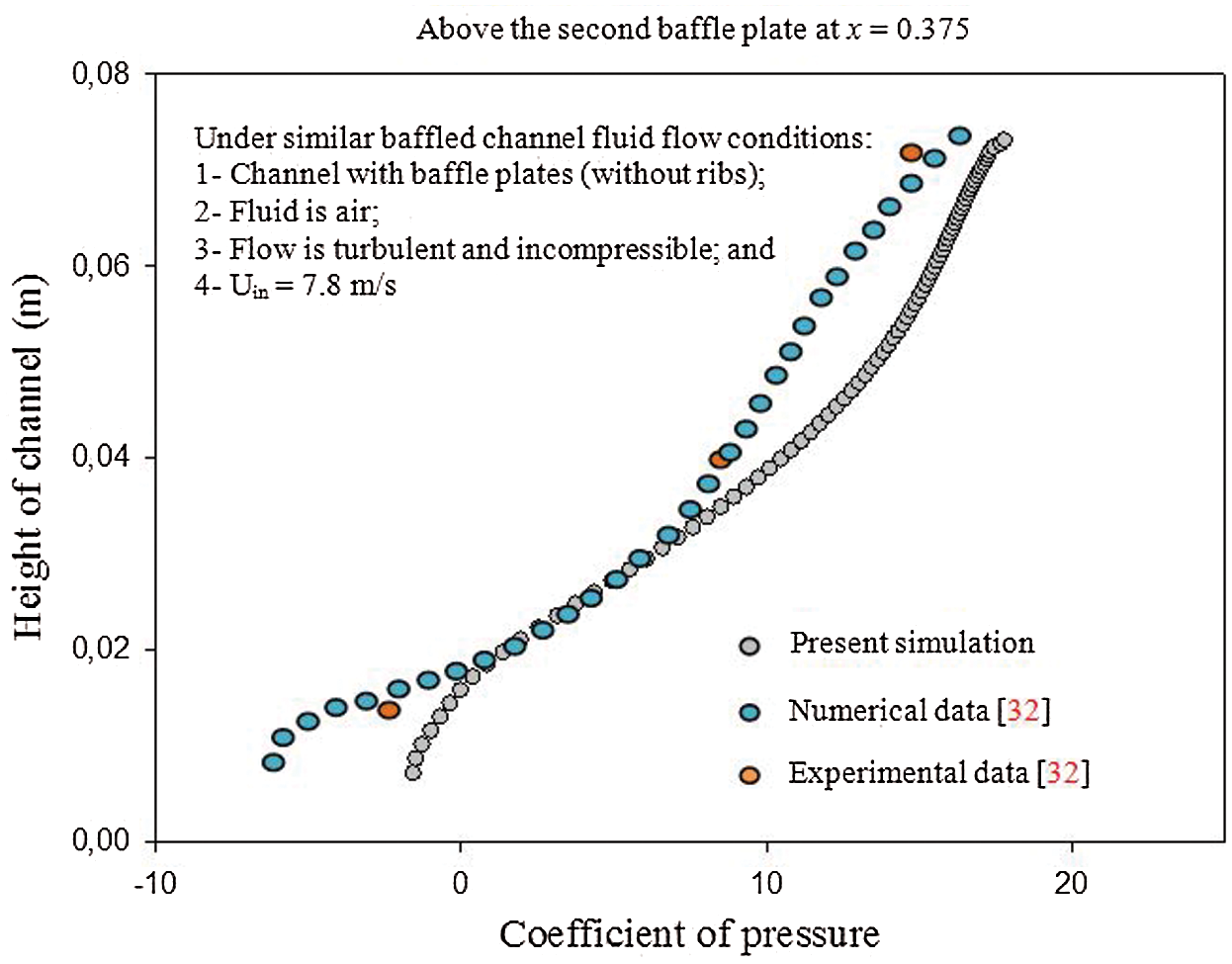
Figure 2: Distribution of the coefficient of pressure along the station (x = 0.375 m,  )
)
The originality of the present work is the implementation of incompressible Newtonian fluid with the ribbing and baffling techniques to enhance the overall performance of the heat exchanger. Therefore, we compared our work against an experimental data of a simple baffled channel without ribs [32]. The working fluid, which is used in the validation plot, is air. After checking the validity of our predicted results, the same numerical approach was used for the new computational configuration.
The streamlines inside the channel heat exchanger at  and for various shaped ribs are presented in Fig. 3. The flow is uniform from the channel inlet and until the upstream of the first obstacle, where a dead volume is formed. The flow is detached from the wall of the baffle, resulting thus in a depression in the downstream area of this VG. The first VG orients the flow towards the lower wall, while the 2nd baffle directs it towards the upper wall.
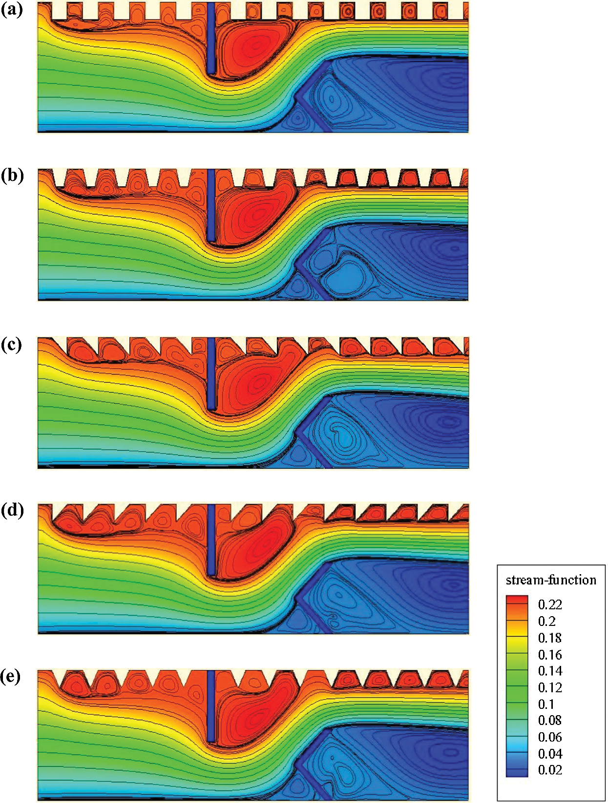
Figure 3: Streamlines ( in kg/s) for various situations of the hot exchanger surface: (a) square-type ribbed surface, (b) trapezoidal-type ribbed surface, (c) triangular I-type ribbed surface, (d) triangular II-type ribbed surface, and (e) triangular III-type ribbed surface,
Furthermore, the second V-baffle yields a smooth airflow along with the main flow direction, which increases the axial velocity and significantly reduces the reattachment length. In general, and for the five types of baffles, a recirculation zone is formed in each region where the roughness is located. The size of these recirculation zones is very significant for the case of triangular-shaped baffles.
The effects of the shape of VGs on the turbulent airflow behavior are highlighted in Fig. 4. The mean velocity fields are plotted at  . The figure indicates the existence of four principle areas. At 1st rib, separated flows with low velocities are remarked for the five configurations studied. In the 2nd area and just upstream of the baffle-type VGs, the axial velocity of the fluid is high. However, the streamlines are deflected when approaching the baffles. In the 3rd area, which concerns the space between the tip of each obstacle and the duct walls, the flow velocity is intensified again due to the reduced passage. In the 4th area, which concerns the downstream of VGs, the streamlines are induced by the influence of the flow expansion. The extension of the recirculating flow that is formed in this area is proportional to the flow intensity.
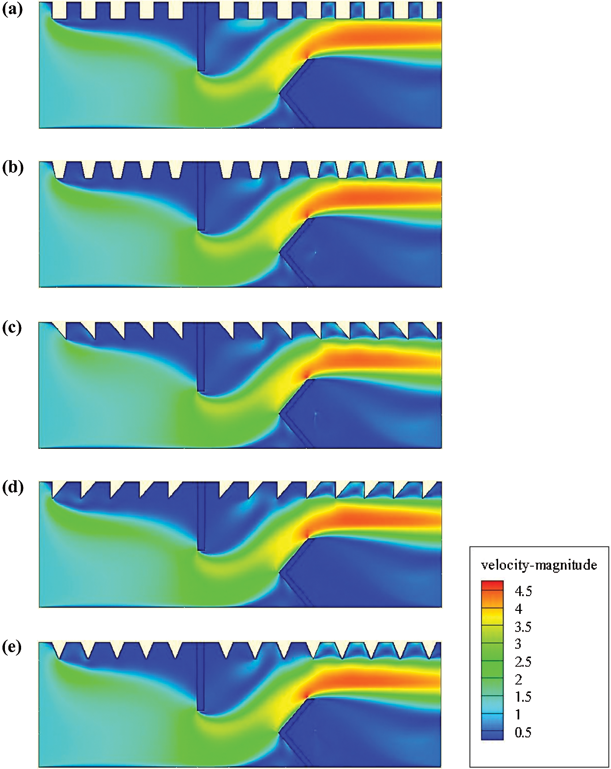
Figure 4: Mean velocity (V in m/s) for various hot exchanger surface-placed rib-type VGs: (a) square-type ribbed surface, (b) trapezoidal-type ribbed surface, (c) triangular I-type ribbed surface, (d) triangular II-type ribbed surface, and (e) triangular III-type ribbed surface, 
Finally, these obstacles augment the length of the flow patterns and intensify the vortex magnitude due to the changes in the streamline’s orientation.
The fields of the axial velocity (u) for various designed baffles are illustrated in Fig. 5. The velocities are almost negligible near the two VGs. However, the streamlines become parallel elsewhere, resulting thus in a progressive development of the flow. Furthermore, high amounts of the axial velocity are remarked in the area between the tip of each VG and the duct wall. Especially, the highest velocities are reached in the vicinity of the baffle tips.
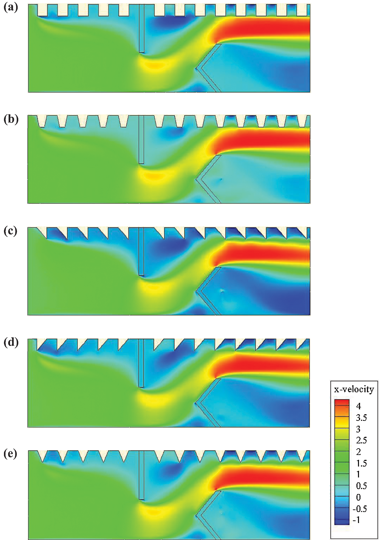
Figure 5: X-velocity (u in m/s) for various roughness geometries: (a) square-type roughness, (b) trapezoidal-type roughness, (c) triangular I-type roughness, (d) triangular II-type roughness, and (e) triangular III-type roughness, 
After the second baffle, the flow is accelerated again to reach the values of about 419.66%–426.91% over the inlet velocity. We note that these maximum values depend on the geometrical shape of the baffle. The maximum axial velocity is reached with the triangular case in type II, while the square baffle yielded the lowest axial velocity. At the same Re and compared with the II-model triangular baffle, the decrease in the axial velocity was about 1.61%, 0.41%, 0.63%, and 1.69% for the square, triangular in I-model, trapezoidal, and the triangular-shaped ribs in III-model, respectively.
For the vertical velocity (v), and for all geometries considered, negative velocity gradients are remarked at the tip of 1st baffle, while positive values are formed at the tip of the 2nd baffle (Fig. 6). Moreover, the use of triangular baffles (type II) has given higher values of v than those with the I-type triangular, III-triangular, square, and trapezoidal configurations by about 4.81%, 7.56%, 8.24%, 7.21%, respectively, at Re = 1.2  104.
104.
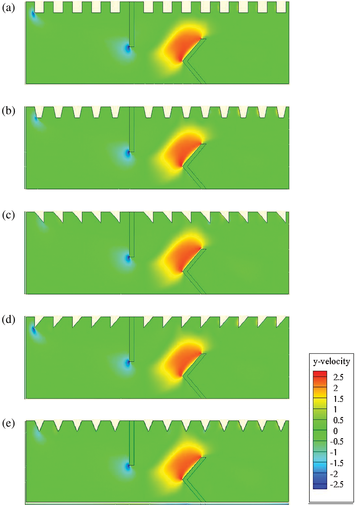
Figure 6: Y-velocity (v in m/s) for various roughness geometries: (a) square-type roughness, (b) trapezoidal-type roughness, (c) triangular I-type roughness, (d) triangular II-type roughness, and (e) triangular III-type roughness, 
The variation of the dynamic pressure is illustrated in Fig. 7 for the different geometrical configurations under investigation. The flow is detached from the baffle tip, which results in a depression downstream of this baffle. Low pressure values are observed behind the baffles due to the existence of recirculation cells. However, the pressure augments in the space between the baffle tip and the duct wall. The dynamic pressure coefficients are the highest near the heated surface of the duct in the region close to the exit due to the high amounts of velocity in these zones. Importantly, the triangular-shaped baffle (type II) suggests more dynamic pressure than that with the triangular (type I), square, trapezoidal, and triangular (type III) baffles by about 9.69%, 7.86%, 6.26%, and 9.24%, respectively.
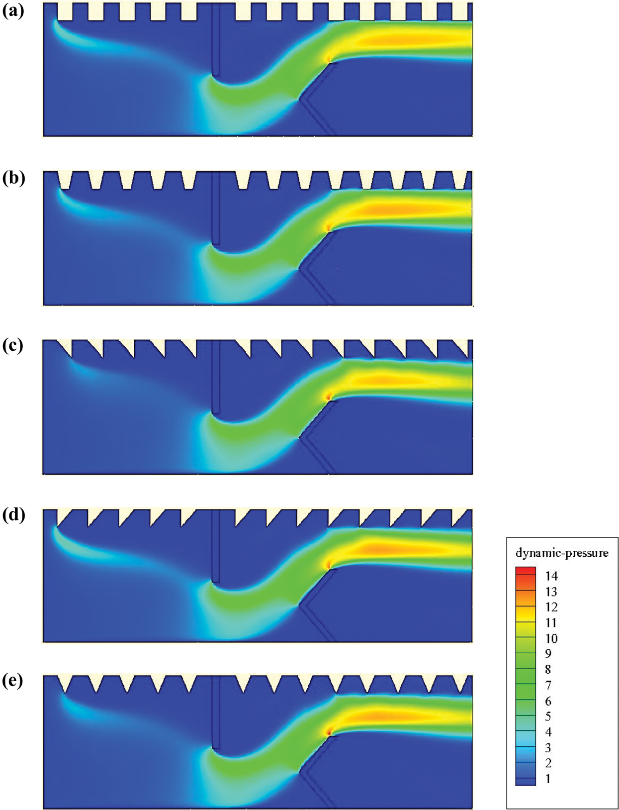
Figure 7: Dynamic-pressure (Pd in Pa) for various hot exchanger surface-placed rib-type VGs: (a) square-type ribbed surface, (b) trapezoidal-type ribbed surface, (c) triangular I-type ribbed surface, (d) triangular II-type ribbed surface, and (e) triangular III-type ribbed surface, 
4.7 Kinetic Energy of Turbulence
The turbulent kinetic energy (k) for different shaped baffles is also computed (Fig. 8). The trends of k variation are identical for all geometries studied. The highest value is observed in front of the first obstacle, while the lowest amount is obtained in the area where the second obstacle is located. Furthermore, the most significant value of k is reached with the triangular-type ribs, while the lowest k is given with the two first geometrical models. More precisely, the square-shaped ribs allowed the lowest amount of k compared with the other cases.
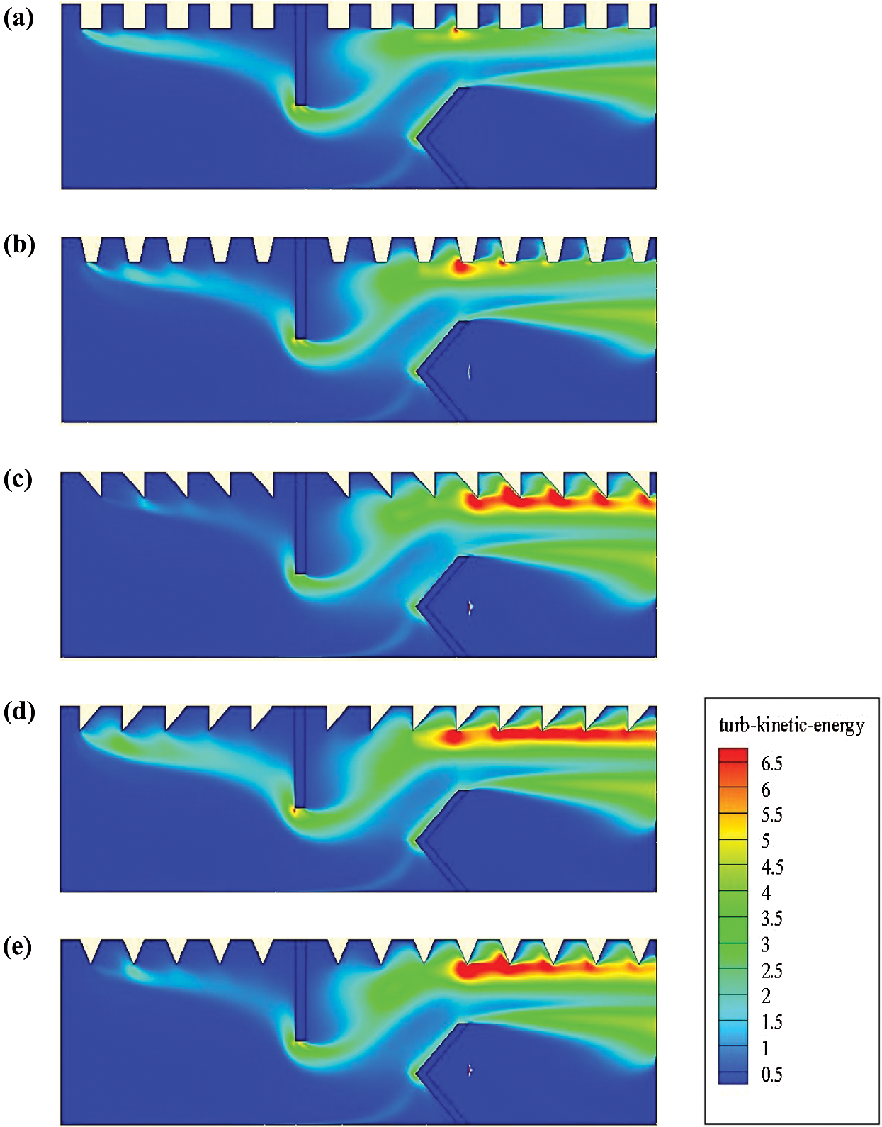
Figure 8: Turbulent kinetic energy (k in m2/s2) for various hot exchanger surface-placed rib-type VGs: (a) square-type ribbed surface, (b) trapezoidal-type ribbed surface, (c) triangular I-type ribbed surface, (d) triangular II-type ribbed surface, and (e) triangular III-type ribbed surface, 
4.8 Dissipation Rate of Turbulence
Fig. 9 illustrates the variation of the turbulent dissipation rate ( ) in the whole computational domain. Many regions in the exchanger are characterized by high amounts of dissipation rates. Beginning from the duct inlet and next to the tip of the first rib; Second, at the flat rectangular baffle next to its upper surface; Third, next to the top left face of the V-shaped VG pointing upstream and also next to its upper face; and Finally, above the V-obstacle and close to the upped side of the exchanger. This is due to the high flow velocities and the effective collision of air particles with the walls in these regions. The comparison between the different cases suggests that the highest dissipations rates are yielded by the triangular type roughness geometries.
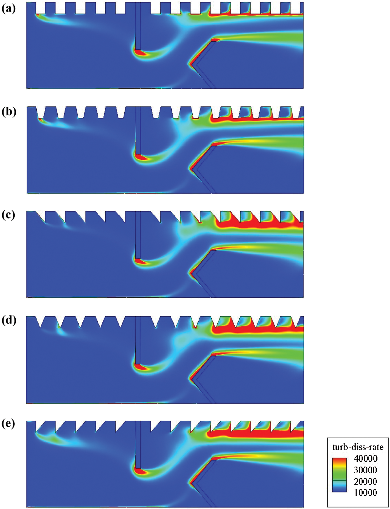
Figure 9: Turbulent dissipation rates ( in m2/s3) for various roughness geometries: (a) square-type roughness, (b) trapezoidal-type roughness, (c) triangular I-type roughness, (d) triangular II-type roughness, and (e) triangular III-type roughness,
The distribution of the temperature fields is also provided at  for all of the shaped roughness geometries under treatment (Fig. 10). For all cases studied, a considerable variation in the temperature is remarked along with the hot wall of the exchanger, more precisely in the baffled region. This means that the main recirculation loops have great impact on the temperature distribution, since they generate good agitation of fluid particles between the hot wall and the core areas. The low thermal exchange areas are located behind the vortex generators.
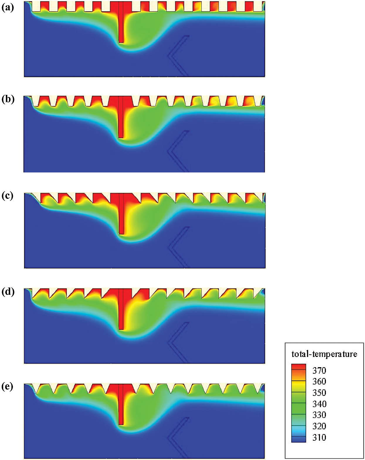
Figure 10: Isotherms (T in K) for various roughness geometries: (a) square-type roughness, (b) trapezoidal-type roughness, (c) triangular I-type roughness, (d) triangular II-type roughness, and (e) triangular III-type roughness, 
The axial velocity profiles (u) just after the 1st and 2nd baffles (i.e., at x = 0.3 and 0.525 m from the inlet) are given in Figs. 11 and 12, respectively. A clear relationship between the velocity profiles, Re, and the various types of roughness surfaces is remarked. Recirculation loops with low velocities are remarked at the two locations of baffles, which is resulted from the flow separation. The velocity magnitude behind the rectangular-shaped VG (at x = 0.3 m, see Fig. 11) is considerably higher than that behind the V-shaped VG (at x = 0. 525 m, see Fig. 12), resulting thus in a difference in the reattachment length and vortex size for the two geometrical models.
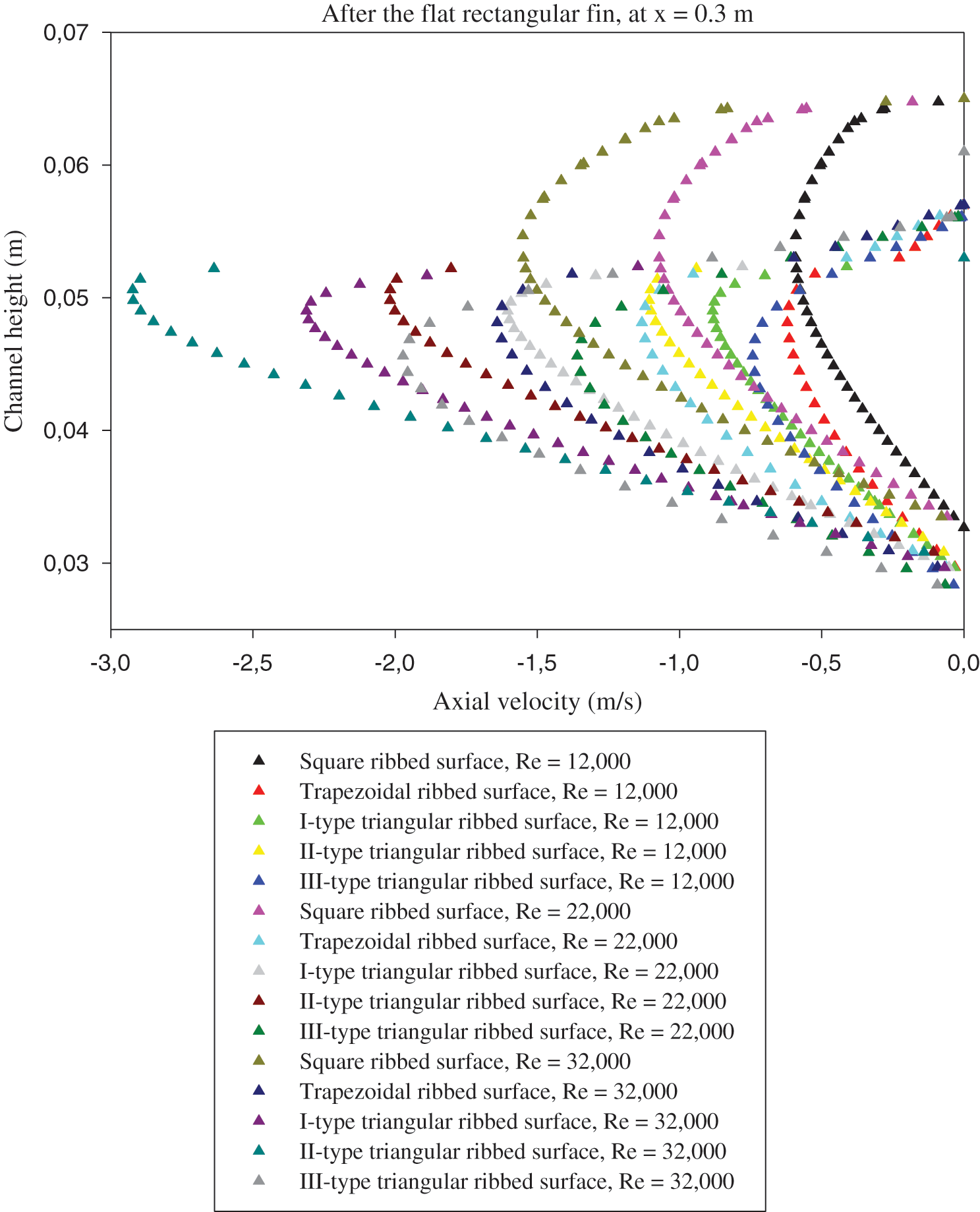
Figure 11: Effects of various roughness situations and different fluid rates on the vortex dynamic-structure, right after the 1st VG, at axial station x = 0.3 m
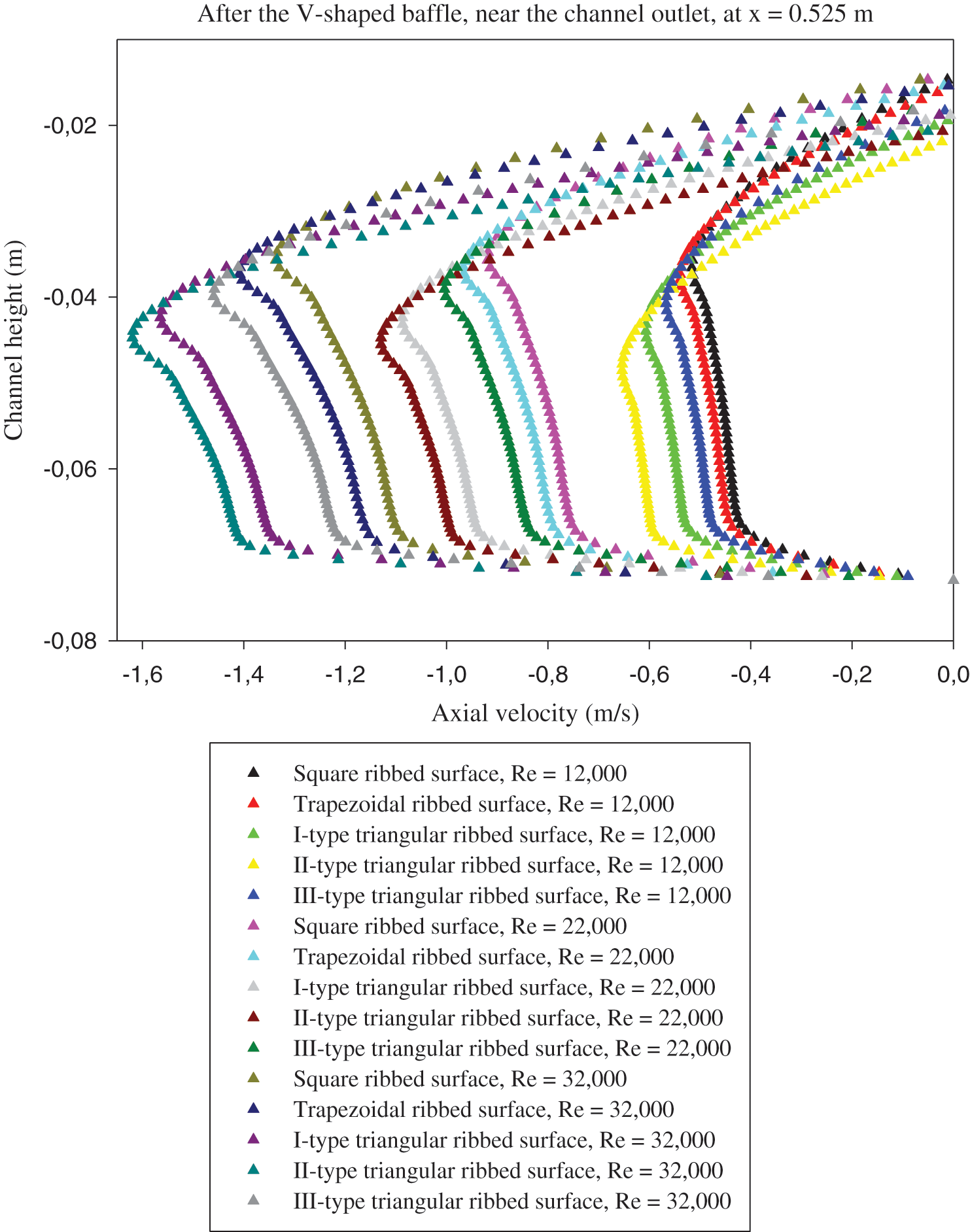
Figure 12: Effects of various roughness situations and different fluid rates on the vortex dynamic-structure, right after the 2nd VG, at axial station x = 0.525 m
The obtained results reveal that the rectangular baffle yields the higher recirculation lengths than those with the V-obstacle, regardless of Re and the baffle design. In addition, the hot obstacle creates an abrupt variation in the velocity, while the insulated V-baffle yields a progressive change in the velocity, which participates in the considerable reduction of the reattachment lengths. The comparison of the recirculation length for the different geometrical configurations of ribs reveals that the triangular obstacle (type II) yields the longest recirculation cell for all Re studied here. Also, the results suggest that the flow rates impact significantly on the vortex size behind the baffles, where the augmentation of Re produced an increased length in the recirculation areas.
The performance ( ) of the proposed heat exchanger with VGs and roughness is given in Fig. 13. Five hot rough surfaces subject to turbulent airflow for different Reynolds number values ranging from
  to
to  are under analysis. The results gave an increase in the performance values, all of which exceeded the unity, which indicates an improvement compared to the case of the smooth channel without VGs and roughness. The presence of rough surfaces with triangular ribs proved their effectiveness compared to those reinforced with square or trapezoidal ribs. The highest performance value is given for the II-triangular rib case in all Re values, while the square-shaped ribs show a significant decrease in the
  along the achieved Re range. The
  value at
  is 2.567 for the II-triangular roughness case [85]. Compared with the other simulated cases, this performance is decreased by about 3.768% in the case of I-triangular ribs [85], 15.249% in the case of III-triangular ribs [85], 20.802% in the case of trapezoidal ribs, while 27.541% in the case of square ribs, at the same
  value. Also, in this study, a comparison is made with heat exchangers that have non-rough walls and contain cross-shaped VGs presented previously [68–77], in order to highlight the effectiveness of the rough surface presence in the baffled and finned channels. The comparison is made at the largest value of the flow rate and as expected, the proposed exchanger with its five different models shows a significant improvement in
  values compared to all cases of using the rib-free baffled and finned air-heat exchangers. The analysis of the
  values and compared to the best
  obtained, i.e., 2.567 for the II-triangular roughness case, the performance decreases greatly in the absence of ribbed surfaces and the presence of VGs (fin and baffle) of the shape of Flat and trapezoidal [68], Flat and triangular [68], Flat and arc [69], V-upstream and V-upstream (VUs) [70–72], Flat and V-upstream (FVU) [68,70,73–75], V-downstream and V-downstream (VDs) [70], Flat and (FVD) [68,70,76], and W and W (Ws) [77], as this reduction is estimated to be about 46.201%, 42.539%, 41.527%, 37.982%, 28.593%, 39.033%, 38.722% and 35.9563%, respectively. This indicates the necessity of roughness heat transfer surfaces for finned and baffled channels to improve significantly the performance of the air-heat exchangers they contain.
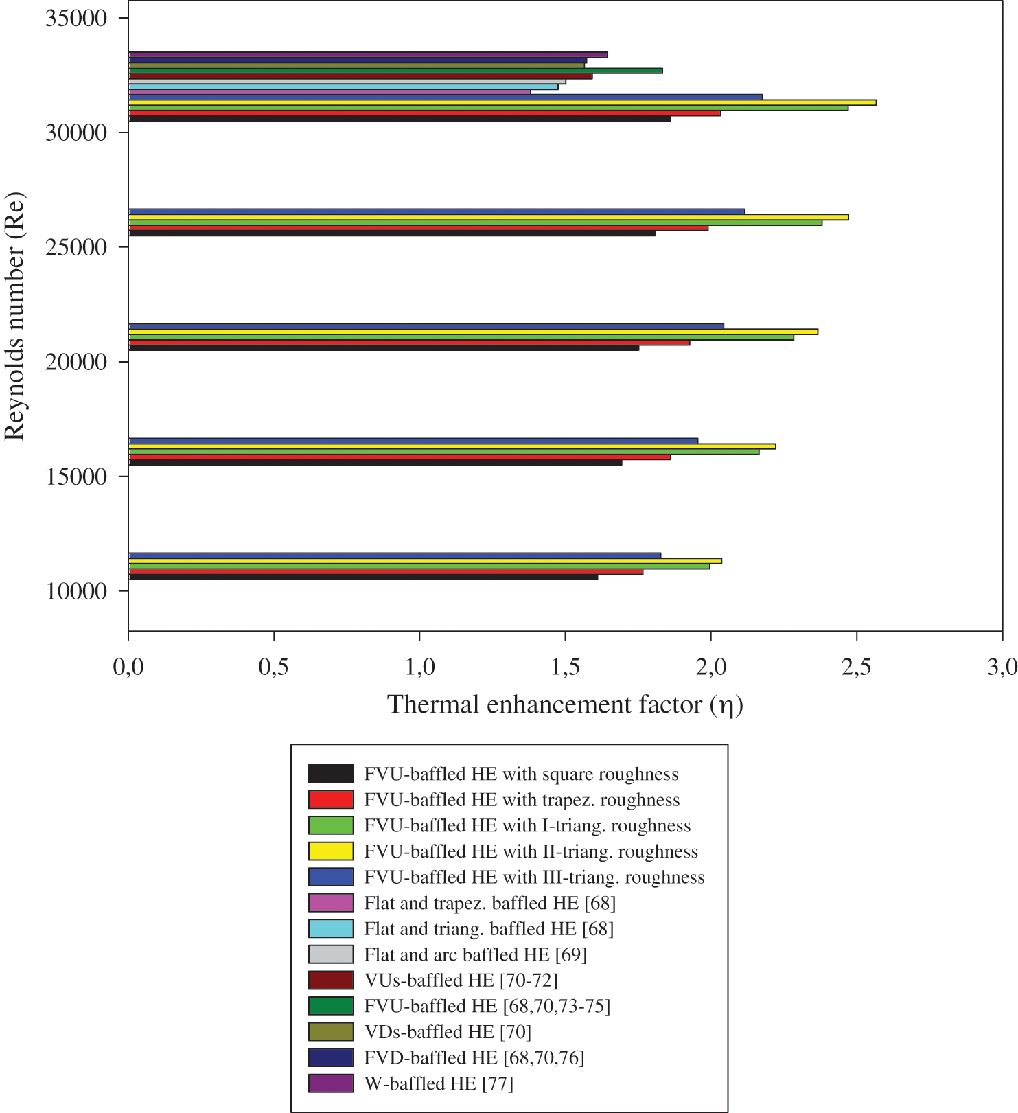
Figure 13: Thermal enhancement factor ( ) for various heat exchangers
The hydrothermal characteristics of air inside a solar duct provided with various designed baffles, i.e., flat and V, under a staggered arrangement have been inspected numerically. Five various roughness situations were considered: trapezoidal, square, triangular pointing upstream (type I), triangular pointing downstream (type II), and equilateral-triangular (type III).
From the several computations, low pressure values were observed behind the baffles due to the existence of recirculation cells. However, the pressure increased in the space between the baffle tip and the duct wall.
The velocity magnitude behind the rectangular-shaped VG is considerably higher than that behind the V-shaped VG, resulting thus in a difference in the reattachment length and vortex size for the two geometrical models. The obtained results reveal that the rectangular baffle yields the higher recirculation lengths than those with the V-obstacle, regardless of Re and the rib design. In addition, the hot obstacle creates an abrupt variation in the velocity, while the insulated V-baffle yields a progressive change in the velocity, which participates in the considerable reduction of the reattachment lengths.
The comparison of the recirculation length for the different geometrical configurations of ribs reveals that the triangular obstacle (type II) yields the longest recirculation cell for all Re studied here. Also, the results suggest that the flow rates impact significantly on the vortex size behind the baffles, where the augmentation of Re produced an increased length in the recirculation areas.
The comparison between the various roughness situations revealed that the triangular baffles (type II) are able to provide the most significant amounts of axial and vertical velocities. At  and compared with the II-model triangular baffle, the decrease in the axial velocity was about 1.61%, 0.41%, 0.63%, and 1.69% for the square, triangular in I-model, trapezoidal, and the triangular-shaped ribs in III-model, respectively. At the same Re, the maximum values of v yielded by the triangular shaped baffle (type II) was higher than those with the I-type triangular, III-triangular, square, and trapezoidal configurations by about 4.81%, 7.56%, 8.24%, 7.21%, respectively.
The most significant value of kinetic-energy of turbulence is reached with the triangular-type ribs, while the lowest kinetic-energy is given with the two first geometrical models. More precisely, the square-shaped ribs allowed the lowest amount of k compared with the other cases. The comparison between the different cases in terms of rates of turbulence dissipation suggested that the highest dissipations rates are yielded by the triangular type roughness geometries.
The higher temperature gradients were located in the baffled regions, while the lower ones were found behind the VGs. This means that the main recirculation loops have great impact on the temperature distribution, since they generate good agitation of fluid particles between the hot wall and the core areas. The low thermal exchange areas are located behind the vortex generators.
The performance evaluation gave an enhancement in the  values, all of which exceeded the unity, which indicates an improvement compared to the case of the smooth channel without VGs and roughness.
The rough surface presence with triangular-type ribs proved their effectiveness compared to those reinforced with square or trapezoidal ribs.
The highest performance value was given for the II-triangular rib case in all Re values, while the square-shaped ribs showed a significant decrease in the  along the achieved Re range.
The  value at
  was 2.567 for the II-triangular roughness case. Compared with the other simulated cases, this performance was decreased by about 3.768% in the case of I-triangular ribs, 15.249% in the case of III-triangular ribs, 20.802% in the case of trapezoidal ribs, while 27.541% in the case of square ribs, at the same
  value.
Also, a comparison was made with heat exchangers that have non-rough walls and contain cross-shaped VGs presented previously, in order to highlight the effectiveness of the rough surface presence in the baffled and finned channels. The comparison was made at the largest value of the flow rate and as expected, the proposed exchanger with its five different models showed a significant improvement in  values compared to all cases of using the rib-free baffled and finned air-heat exchangers.
This highlights the necessity of roughness heat transfer surfaces for finned and baffled channels to improve significantly the performance of the air-heat exchangers they contain.
Funding Statement: The author(s) received no specific funding for this study.
Conflicts of Interest: The authors declare that they have no conflicts of interest to report regarding the present study.
1. Chen, H. T., Liu, L. S., Lee, S. K. (2010). Estimation of heat-transfer characteristics from fins mounted on a horizontal plate in natural convection. Computer Modeling in Engineering & Sciences, 65(2), 155–178, DOI 10.3970/cmes.2010.065.155. [Google Scholar] [CrossRef]
2. Tien, W. C., Yang, Y. T., Chen, C. K. (2012). Application of homotopy analysis method for periodic heat transfer in convective straight fins with temperature-dependent thermal conductivity. Computer Modeling in Engineering & Sciences, 84(2), 155–169, DOI 10.3970/cmes.2012.084.155. [Google Scholar] [CrossRef]
3. El-Askary, W. A., Abdel-Fattah, A. (2012). Experimental and numerical studies on heat transfer and fluid flow in a duct fitted with inclined baffles. Computer Modeling in Engineering & Sciences, 83(4), 425–458, DOI 10.3970/cmes.2012.083.425. [Google Scholar] [CrossRef]
4. Sharma, S. K., Kalamkar, V. R. (2018). Numerical investigation of convective heat transfer and friction in solar air heater with thin ribs. Computer Modeling in Engineering & Sciences, 114(3), 295–319, DOI 10.3970/cmes.2018.114.295. [Google Scholar] [CrossRef]
5. Guan, Y., Hu, W., Zhang, Y., Song, K., Wang, L. (2020). Numerical study of the intensity correlation between secondary flow and heat transfer of circle tube-finned heat exchanger with vortex generators. Computer Modeling in Engineering & Sciences, 123(1), 237–256. DOI 10.32604/cmes.2021.09141. [Google Scholar] [CrossRef]
6. Menasria, F., Zedairia, M., Moummi, A. (2017). Numerical study of thermohydraulic performance of solar air heater duct equipped with novel continuous rectangular baffles with high aspect ratio. Energy, 133, 593–608. DOI 10.1016/j.energy.2017.05.002. [Google Scholar] [CrossRef]
7. Tan, Y., He, Z., Xu, T., Fang, X., Gao, X. et al. (2017). Experimental investigation of heat transfer and pressure drop characteristics of non-Newtonian nanofluids flowing in the shell-side of a helical baffle heat exchanger with low-finned tubes. Heat and Mass Transfer, 53(9), 2813–2827. DOI 10.1007/s00231-017-2015-6. [Google Scholar] [CrossRef]
8. Ghritlahre, H. K., Prasad, R. K. (2018). Prediction of heat transfer of two different types of roughened solar air heater using artificial neural network technique. Thermal Science and Engineering Progress, 8, 145–153. DOI 10.1016/j.tsep.2018.08.014. [Google Scholar] [CrossRef]
9. Shirvan, K. M., Mamourian, M., Esfahani, J. A. (2019). Experimental study on thermal analysis of a novel shell and tube heat exchanger with corrugated tubes. Journal of Thermal Analysis and Calorimetry, 138(2), 1583–1606. DOI 10.1007/s10973-019-08308-3. [Google Scholar] [CrossRef]
10. Baissi, M. T., Brima, A., Aoues, K., Khanniche, R., Moummi, N. (2020). Thermal behavior in a solar air heater channel roughened with delta-shaped vortex generators. Applied Thermal Engineering, 165, 113563. DOI 10.1016/j.applthermaleng.2019.03.134. [Google Scholar] [CrossRef]
11. Tarasevich, S. E., Shishkin, A. V., Giniyatullin, A. A. (2020). Heat transfer in a channel with ribbed twisted tapes. High Temperature, 58(1), 107–111. DOI 10.1134/S0018151X20010216. [Google Scholar] [CrossRef]
12. Omari, B., Mataoui, A., Salem, A. (2020). Analysis of turbulent flow in a channel roughened by two-dimensional ribs: Effect of first rib width. Thermophysics and Aeromechanics, 27(1), 45–59. DOI 10.1134/S0869864320010047. [Google Scholar] [CrossRef]
13. Gorelov, Y. G. (2020). 3D Investigations of heat exchange and hydrodynamics in channels with different combinations of ribs and oval-trench dimples. Russian Aeronautics, 63(1), 137–146. DOI 10.3103/S1068799820010201. [Google Scholar] [CrossRef]
14. Joseph, M. P., Mathew, G., Krishnaraj, G. G., Dilip, D., Ranjith, S. K. (2020). Numerical simulation of liquid–gas interface formation in long superhydrophobic microchannels with transverse ribs and grooves. Experimental and Computational Multiphase Flow, 2(3), 162–173. DOI 10.1007/s42757-019-0043-9. [Google Scholar] [CrossRef]
15. Kumar, R., Nadda, R., Rana, A., Chauhan, R., Chandel, S. S. (2020). Performance investigation of a solar thermal collector provided with air jets impingement on multi V-shaped protrusion ribs absorber plate. Heat and Mass Transfer, 56(3), 913–930. DOI 10.1007/s00231-019-02755-2. [Google Scholar] [CrossRef]
16. Patankar, S. V., Liu, C. H., Sparrow, E. M. (1977). Fully developed flow and heat transfer in ducts having streamwise-periodic variations of cross-sectional area. Journal of Heat Transfer, 99(2), 180–186. DOI 10.1115/1.3450666. [Google Scholar] [CrossRef]
17. Kelkar, K. M., Patankar, S. V. (1987). Numerical prediction of flow and heat transfer in a parallel plate channel with staggered fins. Journal Heat Transfer, 109(1), 25–30. DOI 10.1115/1.3248058. [Google Scholar] [CrossRef]
18. Webb, B. W., Ramadhyani, S. (1985). Conjugate heat transfer in a channel with staggered ribs. International Journal of Heat and Mass Transfer, 28(9), 1679–1687. DOI 10.1016/0017-9310(85)90142-5. [Google Scholar] [CrossRef]
19. Lopez, J. R., Anand, N. K., Fletcher, L. S. (1996). Heat transfer in a three-dimensional channel with baffles. Numerical Heat Transfer, Part A, 30(2), 189–205. DOI 10.1080/10407789608913835. [Google Scholar] [CrossRef]
20. Cheng, C. H., Huang, W. H. (1991). Numerical prediction for laminar forced convection in parallel-plate channels with transverse fin arrays. International Journal of Heat and Mass Transfer, 34(11), 2739–2749. DOI 10.1016/0017-9310(91)90232-4. [Google Scholar] [CrossRef]
21. Guo, Z., Anand, N. K. (1997). Three-dimensional heat transfer in a channel with a baffle in the entrance region. Numerical Heat Transfer, Part A, 31(1), 21–35. DOI 10.1080/10407789708914023. [Google Scholar] [CrossRef]
22. Bazdidi-Tehrani, F., Naderi-Abadi, M. (2004). Numerical analysis of laminar heat transfer in entrance region of a horizontal channel with transverse fins. International Communication in Heat and Mass Transfer, 31(2), 211–220. DOI 10.1016/S0735-1933(03)00226-4. [Google Scholar] [CrossRef]
23. Hwang, R. R., Chow, Y. C., Peng, Y. F. (1999). Numerical study of turbulent flow over tow-dimensional surface-mounted ribs in a channel. International Journal for Numerical Methods in Fluids, 37, 767–785. DOI 10.1002/(SICI)1097-0363(19991030)31:4¡767::AID-FLD902¿3.0.CO;2-A. [Google Scholar] [CrossRef]
24. Yuan, Z. X., Tao, W. Q. (1998). Numerical prediction for laminar forced convection heat transfer in parallel-plate channels with streamwise-periodic rod disturbances. International Journal for Numerical Methods in Fluids, 28, 1371–1387. [Google Scholar]
25. Tsay, Y. L., Chang, T. S., Cheng, J. C. (2005). Heat transfer enhancement of backward-facing step flow in a channel by using baffle installed on the channel wall. Acta Mechanica, 174(1–2), 63–76. DOI 10.1007/s00707-004-0147-5. [Google Scholar] [CrossRef]
26. Pirouz, M. M., Farhadi, M., Sedighi, K., Nemati, H., Fattahi, E. (2011). Lattice Boltzmann simulation of conjugate heat transfer in a rectangular channel with wall-mounted obstacles. Scientia Iranica B, 18(2), 213–221. DOI 10.1016/j.scient.2011.03.016. [Google Scholar] [CrossRef]
27. Chien, L. H., Liao, W. R., Ghalambaz, M., Yan, W. M. (2019). Experimental study on convective boiling of micro-pin-finned channels with parallel arrangement fins for FC-72 dielectric fluid. International Journal of Heat and Mass Transfer, 138, 390–400. DOI 10.1016/j.ijheatmasstransfer.2019.04.072. [Google Scholar] [CrossRef]
28. Chien, L. H., Cheng, Y. T., Lai, Y. L., Yan, W. M., Ghalambaz, M. (2020). Experimental and numerical study on convective boiling in a staggered array of micro pin-fin microgap. International Journal of Heat and Mass Transfer, 149, 119203. DOI 10.1016/j.ijheatmasstransfer.2019.119203. [Google Scholar] [CrossRef]
29. Nasiruddin, Siddiqui, M. H. K. (2007). Heat transfer augmentation in a heat exchanger tube using a baffle. International Journal of Heat and Fluid Flow, 28(2), 318–328. DOI 10.1016/j.ijheatfluidflow.2006.03.020. [Google Scholar] [CrossRef]
30. Mousavi, S. S., Hooman, K. (2006). Heat and fluid flow in entrance region of a channel with staggered baffles. Energy Conversion and Management, 47(15), 2011–2019. DOI 10.1016/j.enconman.2005.12.018. [Google Scholar] [CrossRef]
31. Tandiroglu, A., Ayhan, T. (2006). Energy dissipation analysis of transient heat transfer for turbulent flow in a circular tube with baffle inserts. Applied Thermal Engineering, 26(2), 178–185. DOI 10.1016/j.applthermaleng.2005.05.018. [Google Scholar] [CrossRef]
32. Demartini, L. C., Vielmo, H. A., Möller, S. V. (2004). Numeric and experimental analysis of the turbulent flow through a channel with baffle plates. Journal of the Brazilian Society of Mechanical Sciences and Engineering, 26(2), 153–159. DOI 10.1590/S1678-58782004000200006. [Google Scholar] [CrossRef]
33. Acharya, S., Dutta, S., Myrum, T. A. (1998). Heat transfer in turbulent flow past a surface-mounted two-dimensional rib. Transactions of the ASME, 120(3), 724–734. DOI 10.1115/1.2824342. [Google Scholar] [CrossRef]
34. Ghanbari, S., Javaherdeh, K. (2020). Thermal performance enhancement in perforated baffled annuli by nanoporous graphene non-Newtonian nanofluid. Applied Thermal Engineering, 167, 114719. DOI 10.1016/j.applthermaleng.2019.114719. [Google Scholar] [CrossRef]
35. Karami, R., Kamkari, B. (2020). Experimental investigation of the effect of perforated fins on thermal performance enhancement of vertical shell and tube latent heat energy storage systems. Energy Conversion and Management, 210, 112679. DOI 10.1016/j.enconman.2020.112679. [Google Scholar] [CrossRef]
36. Wu, G., Yu, B., Ren, T., Ding, G. (2020). Modeling and experimental investigation on comprehensive performance of perforated wavy fins for heat pump type air conditioners at frosting and non-frosting conditions. Energy and Buildings, 225, 110342. DOI 10.1016/j.enbuild.2020.110342. [Google Scholar] [CrossRef]
37. Chamoli, S. (2015). ANN and RSM approach for modeling and optimization of designing parameters for a V down perforated baffle roughened rectangular channel. Alexandria Engineering Journal, 54(3), 429–446. DOI 10.1016/j.aej.2015.03.018. [Google Scholar] [CrossRef]
38. Mana, A. A., Sonti, V. R. (2019). Sound radiation from a finite perforated panel set in a rigid baffle: A fully coupled analysis. Wave Motion, 85, 144–164. DOI 10.1016/j.wavemoti.2018.11.004. [Google Scholar] [CrossRef]
39. Chang, S. W., Chen, T. W., Chen, Y. W. (2019). Detailed heat transfer and friction factor measurements for square channel enhanced by plate insert with inclined baffles and perforated slots. Applied Thermal Engineering, 159, 113856. DOI 10.1016/j.applthermaleng.2019.113856. [Google Scholar] [CrossRef]
40. Salem, M. R., Althafeeri, M. K., Elshazly, K. M., Higazy, M. G., Abdrabbo, M. F. (2017). Experimental investigation on the thermal performance of a double pipe heat exchanger with segmental perforated baffles. International Journal of Thermal Sciences, 122, 39–52. DOI 10.1016/j.ijthermalsci.2017.08.008. [Google Scholar] [CrossRef]
41. Ghanbari, S., Javaherdeh, K. (2020). Investigation of applying nanoporous graphene non-Newtonian nanofluid on rheological properties and thermal performance in a turbulent annular flow with perforated baffles. Journal of Thermal Analysis and Calorimetry, 139(1), 629–647. DOI 10.1007/s10973-019-08389-0. [Google Scholar] [CrossRef]
42. Jeong, M. H., Kumaresh, S. K., Kim, M. Y., Kim, C. (2018). A numerical study on the flow performance inside the straight pipe with perforated plates. Journal of Mechanical Science and Technology, 32(7), 3183–3189. DOI 10.1007/s12206-018-0621-y. [Google Scholar] [CrossRef]
43. Gautam, A., Pandey, L., Singh, S. (2018). Influence of perforated triple wing vortex generator on a turbulent flow through a circular tube. Heat and Mass Transfer, 54(7), 2009–2021. DOI 10.1007/s00231-018-2296-4. [Google Scholar] [CrossRef]
44. Dutta, P., Dutta, S. (1998). Effect of baffle size, perforation, and orientation on internal heat transfer enhancement. International Journal of Heat & Mass Transfer, 41(19), 3005–3013. DOI 10.1016/S0017-9310(98)00016-7. [Google Scholar] [CrossRef]
45. Dutta, P., Hossain, A. (2005). Internal cooling augmentation in rectangular channel using two inclined baffles. International Journal of Heat & Fluid Flow, 26(2), 223–232. [Google Scholar]
46. Dutta, S., Dutta, P., Jones, R. E., Khan, J. A. (1998). Heat transfer coefficient enhancement with perforated baffles. Journal of Heat Transfer, 120(3), 795–797. DOI 10.1115/1.2824356. [Google Scholar] [CrossRef]
47. Salhi, J. E., Salhi, N. (2021). Three-dimensional analysis of the effect of transverse spacing between perforations of a deflector in a heat exchanger. In: Hajji, B., Mellit, A., Marco Tina, G., Rabhi, A., Launay, J., Naimi, S., (Eds.Proceedings of the 2nd International Conference on Electronic Engineering and Renewable Energy Systems. ICEERE 2020. Lecture Notes in Electrical Engineering. vol. 681. Singapore: Springer, DOI 10.1007/978-981-15-6259-4_75. [Google Scholar] [CrossRef]
48. Abbasi, H. R., Sadeh, E. S., Pourrahmani, H., Mohammadi, M. H. (2020). Shape optimization of segmental porous baffles for enhanced thermo-hydraulic performance of shell-and-tube heat exchanger. Applied Thermal Engineering, 180, 115835. DOI 10.1016/j.applthermaleng.2020.115835. [Google Scholar] [CrossRef]
49. Tian, H., Zhao, T., Shi, L., Chen, T., Ma, X. et al. (2020). Assessment and optimization of exhaust gas heat exchanger with porous baffles and porous fins. Applied Thermal Engineering, 178, 115446. DOI 10.1016/j.applthermaleng.2020.115446. [Google Scholar] [CrossRef]
50. Mohammadi, M. H., Abbasi, H. R., Yavarinasab, A., Pourrahmani, H. (2020). Thermal optimization of shell and tube heat exchanger using porous baffles. Applied Thermal Engineering, 170, 115005. DOI 10.1016/j.applthermaleng.2020.115005. [Google Scholar] [CrossRef]
51. Li, F., Ma, Q., Xin, G., Zhang, J., Wang, X. (2020). Heat transfer and flow characteristics of microchannels with solid and porous ribs. Applied Thermal Engineering, 178, 115639. DOI 10.1016/j.applthermaleng.2020.115639. [Google Scholar] [CrossRef]
52. Wang, T. H., Wu, H. C., Meng, J. H., Yan, W. M. (2020). Optimization of a double-layered microchannel heat sink with semi-porous-ribs by multi-objective genetic algorithm. International Journal of Heat and Mass Transfer, 149, 119217. DOI 10.1016/j.ijheatmasstransfer.2019.119217. [Google Scholar] [CrossRef]
53. Pourrahmani, H., Moghimi, M., Siavashi, M., Shirbani, M. (2019). Sensitivity analysis and performance evaluation of the PEMFC using wave-like porous ribs. Applied Thermal Engineering, 150, 433–444. DOI 10.1016/j.applthermaleng.2019.01.010. [Google Scholar] [CrossRef]
54. Kiwan, S., Alwan, H., Abdelal, N. (2020). An experimental investigation of the natural convection heat transfer from a vertical cylinder using porous fins. Applied Thermal Engineering, 179, 115673. DOI 10.1016/j.applthermaleng.2020.115673. [Google Scholar] [CrossRef]
55. Esfe, M. H., Barzegarian, R., Bahiraei, M. (2020). A 3D numerical study on natural convection flow of nanofluid inside a cubical cavity equipped with porous fins using two-phase mixture model. Advanced Powder Technology, 31(6), 2480–2492. DOI 10.1016/j.apt.2020.04.012. [Google Scholar] [CrossRef]
56. Gupta, A., Sahoo, S., Mohanty, A. (2020). Performance evaluation of porous fin with prescribed tip temperature: An analytical and numerical approach. International Journal of Heat and Mass Transfer, 156, 119736. DOI 10.1016/j.ijheatmasstransfer.2020.119736. [Google Scholar] [CrossRef]
57. Zhao, T., Tian, H., Shi, L., Chen, T., Ma, X. et al. (2020). Numerical analysis of flow characteristics and heat transfer of high-temperature exhaust gas through porous fins. Applied Thermal Engineering, 165, 114612. DOI 10.1016/j.applthermaleng.2019.114612. [Google Scholar] [CrossRef]
58. Toghraie, D., Mahmoudi, M., Akbari, O. A., Pourfattah, F., Heydari, M. (2019). The effect of using water/CuO nanofluid and L-shaped porous ribs on the performance evaluation criterion of microchannels. Journal of Thermal Analysis and Calorimetry, 135(1), 145–159. DOI 10.1007/s10973-018-7254-3. [Google Scholar] [CrossRef]
59. Wang, S. L., Chen, L. Y., Zhang, B. X., Yang, Y. R., Wang, X. D. (2020). A new design of double-layered microchannel heat sinks with wavy microchannels and porous-ribs. Journal of Thermal Analysis and Calorimetry, 141(1), 547–558. DOI 10.1007/s10973-020-09317-3. [Google Scholar] [CrossRef]
60. Siavashi, M., Bahrami, H. R. T., Aminian, E., Saffari, H. (2019). Numerical analysis on forced convection enhancement in an annulus using porous ribs and nanoparticle addition to base fluid. Journal of Central South University, 26(5), 1089–1098. DOI 10.1007/s11771-019-4073-z. [Google Scholar] [CrossRef]
61. Shamsabadi, H., Rashidi, S., Esfahani, J. A. (2019). Entropy generation analysis for nanofluid flow inside a duct equipped with porous baffles. Journal of Thermal Analysis and Calorimetry, 135(2), 1009–1019. DOI 10.1007/s10973-018-7350-4. [Google Scholar] [CrossRef]
62. Mesgarpour, M., Heydari, A., Saddodin, S. (2019). Investigating the effect of connection type of a sintered porous fin through a channel on heat transfer and fluid flow. Journal of Thermal Analysis and Calorimetry, 135(1), 461–474. DOI 10.1007/s10973-018-7356-y. [Google Scholar] [CrossRef]
63. Kiwan, S. (2019). On the natural convection heat transfer from an inclined surface with porous fins. Transport in Porous Media, 127(2), 295–307. DOI 10.1007/s11242-018-1192-1. [Google Scholar] [CrossRef]
64. Nabati, M., Jalalvand, M., Taherifar, S. (2020). Sinc collocation approach through thermal analysis of porous fin with magnetic field. Journal of Thermal Analysis and Calorimetry, 33(3), 698. DOI 10.1007/s10973-020-09923-1. [Google Scholar] [CrossRef]
65. Sowmya, G., Gireesha, B. J., Berrehal, H. (2020). An unsteady thermal investigation of a wetted longitudinal porous fin of different profiles. Journal of Thermal Analysis and Calorimetry, 123(4), 790. DOI 10.1007/s10973-020-09963-7. [Google Scholar] [CrossRef]
66. Ghalambaz, M., Mehryan, S. A. M., Mozaffari, M., Zadeh, S. M. H., Pour, M. S. (2020). Study of thermal and hydrodynamic characteristics of water-nano-encapsulated phase change particles suspension in an annulus of a porous eccentric horizontal cylinder. International Journal of Heat and Mass Transfer, 156, 119792. DOI 10.1016/j.ijheatmasstransfer.2020.119792. [Google Scholar] [CrossRef]
67. Ho, C. J., Liu, Y. C., Ghalambaz, M., Yan, W. M. (2020). Forced convection heat transfer of Nano-Encapsulated Phase Change Material (NEPCM) suspension in a mini-channel heatsink. International Journal of Heat and Mass Transfer, 155, 119858. DOI 10.1016/j.ijheatmasstransfer.2020.119858. [Google Scholar] [CrossRef]
68. Menni, Y., Azzi, A. (2018). Design and performance evaluation of air solar channels with diverse baffle structures. Computational Thermal Sciences, 10(3), 225–249. [Google Scholar]
69. Menni, Y., Chamkha, A. J., Azzi, A., Zidani, C., Benyoucef, B. (2019). Study of air flow around flat and arc-shaped baffles in shell-and-tube heat exchangers. Mathematical Modelling of Engineering Problems, 6(1), 77–84. DOI 10.18280/mmep.060110. [Google Scholar] [CrossRef]
70. Menni, Y., Chamkha, A., Zidani, C., Benyoucef, B. (2019). Baffle orientation and geometry effects on turbulent heat transfer of a constant property incompressible fluid flow inside a rectangular channel. International Journal of Numerical Methods for Heat & Fluid Flow, 30(6), 3027–3052. DOI 10.1108/HFF-12-2018-0718. [Google Scholar] [CrossRef]
71. Menni, Y., Azzi, A. (2018). Computational fluid dynamical analysis of turbulent heat transfer in a channel fitted with staggered V-Shaped baffles. World Journal of Modelling and Simulation, 14(2), 108–123. [Google Scholar]
72. Menni, Y., Chamkha, A. J., Zidani, C., Benyoucef, B. (2020). Analysis of thermo-hydraulic performance of a solar air heater tube with modern obstacles. Archives of Thermodynamics, 41(3), 33–56. [Google Scholar]
73. Menni, Y., Azzi, A., Didi, F., Harmand, S. (2018). Computational fluid dynamical analysis of new obstacle design and its impact on the heat transfer enhancement in a specific type of air flow geometry. Computational Thermal Sciences, 10(5), 421–447. DOI 10.1615/ComputThermalScien.2018024416. [Google Scholar] [CrossRef]
74. Menni, Y., Azzi, A., Chamkha, A. J., Harmand, S. (2018). Effect of wall-mounted V-baffle position in a turbulent flow through a channel: Analysis of best configuration for optimal heat transfer. International Journal of Numerical Methods for Heat & Fluid Flow, 29(10), 3908–3937. DOI 10.1108/HFF-06-2018-0270.
75. Menni, Y., Chamkha, A. J., Azzi, A., Zidani, C. (2020). Numerical analysis of fluid flow and heat transfer characteristics of a new kind of vortex generators by comparison with those of traditional vortex generators. International Journal of Fluid Mechanics Research, 47(1), 23–42. DOI 10.1615/InterJFluidMechRes.2019026753. [Google Scholar] [CrossRef]
76. Menni, Y., Azzi, A., Chamkha, A. J. (2019). Computational thermal analysis of turbulent forced-convection flow in an air channel with a flat rectangular fin and downstream v-shaped baffle. Heat Transfer Research, 50(18), 1781–1818. DOI 10.1615/HeatTransRes.2019026143. [Google Scholar] [CrossRef]
77. Menni, Y., Chamkha, A. J., Makinde, O. D. (2020). Turbulent heat transfer characteristics of a w-baffled channel flow-heat transfer aspect. Defect and Diffusion Forum, 401, 117–130. DOI 10.4028/www.scientific.net/DDF.401.117. [Google Scholar] [CrossRef]
78. Sripattanapipat, S., Promvonge, P. (2009). Numerical analysis of laminar heat transfer in a channel with diamond-shaped baffles. International Communications in Heat and Mass Transfer, 36(1), 32–38. DOI 10.1016/j.icheatmasstransfer.2008.09.008. [Google Scholar] [CrossRef]
79. Wang, F., Zhang, J., Wang, S. (2012). Investigation on flow and heat transfer characteristics in rectangular channel with drop-shaped pin fins. Propulsion and Power Research, 1(1), 64–70. DOI 10.1016/j.jppr.2012.10.003. [Google Scholar] [CrossRef]
80. Abene, A., Dubois, V., Le, R. M., Ouagued, A. (2004). Study of a solar air flat plate collector: Use of obstacles and application for the drying of grape. Journal of Food Engineering, 65(1), 15–22. DOI 10.1016/j.jfoodeng.2003.11.002. [Google Scholar] [CrossRef]
81. Kwankaomeng, S., Promvonge, P. (2010). Numerical prediction on laminar heat transfer in square duct with 30 angled baffle on one wall. International Communication in Heat & Mass Transfer, 37(7), 857–866. DOI 10.1016/j.icheatmasstransfer.2010.05.005. [Google Scholar] [CrossRef]
82. Stehlik, P., Nemcansky, J., Kral, D. (1994). Comparison of correction factors for shell-and-tube heat exchangers with segmental or helical baffles. Heat Transfer Engineering, 15(1), 55–65. DOI 10.1080/01457639408939818. [Google Scholar] [CrossRef]
83. Peng, B., Wang, Q. W., Zhang, C., Xie, G. N., Luo, L. Q. et al. (2007). An experimental study of shell-and-tube heat exchangers with continuous helical baffles. Journal of Heat Transfer, 129(10), 1425–1431. DOI 10.1115/1.2754878. [Google Scholar] [CrossRef]
84. Sriromreun, P., Thianpong, C., Promvonge, P. (2012). Experimental and numerical study on heat transfer enhancement in a channel with z-shaped baffles. International Communication in Heat & Mass Transfer, 39(7), 945–952. DOI 10.1016/j.icheatmasstransfer.2012.05.016. [Google Scholar] [CrossRef]
85. Menni, Y., Chamkha, A. J., Lorenzini, G., Benyoucef, B. (2019). Computational fluid dynamics based numerical simulation of thermal and thermo-hydraulic performance of a solar air heater channel having various ribs on absorber plates. Mathematical Modelling of Engineering Problems, 6(2), 170–174. DOI 10.18280/mmep.060203. [Google Scholar] [CrossRef]
86. Launder, B. E., Spalding, D. B. (1974). The numerical computation of turbulent flows. Computer Methods in Applied Mechanics and Engineering, 3(2), 269–289. DOI 10.1016/0045-7825(74)90029-2. [Google Scholar] [CrossRef]
87. Dittus, F. W., Boelter, L. M. K. (1985). Heat transfer in automobile radiators of the tubular type. International Communications in Heat and Mass Transfer, 12(1), 3–22. DOI 10.1016/0735-1933(85)90003-X. [Google Scholar] [CrossRef]
88. Petukhov, B. S. (1970). Heat transfer and friction in turbulent pipe flow with variable physical properties. Advances in Heat Transfer, 6, 503–564. [Google Scholar]
89. Patankar, S. V. (1980). Numerical heat transfer and fluid flow. New York: Hemisphere Publis- hing Corporation. [Google Scholar]
90. Leonard, B. P., Mokhtari, S. (1990). ULTRA-SHARP nonoscillatory convection schemes for high-speed steady multidimensional flow. NASA TM 1-2568, NASA Lewis Research Center. [Google Scholar]
 | This work is licensed under a Creative Commons Attribution 4.0 International License, which permits unrestricted use, distribution, and reproduction in any medium, provided the original work is properly cited. |